Power transformers are available in single-phase and three-phase configurations, each serving distinct roles in electrical power systems. While they share the same fundamental function—voltage transformation—their design, application, and usage environments differ significantly. Understanding the differences between single-phase and three-phase transformers is essential for selecting the right equipment for residential, commercial, and industrial operations.
What Is a Single-Phase Transformer and How Does It Work?
Single-phase transformers are among the most widely used types of transformers in power distribution and equipment applications. From residential power supply to control panels, industrial machines, and rural grid connections, they play a critical role in voltage transformation where three-phase power is not necessary or available.
A single-phase transformer is an electrical device that converts alternating voltage from one level to another using electromagnetic induction. It consists of a magnetic core and two windings—primary and secondary—wound on the same limb. When an alternating voltage is applied to the primary winding, it creates a magnetic flux in the core, inducing a proportional voltage in the secondary winding according to the turns ratio.
This simple yet powerful principle allows safe, efficient voltage transformation for single-phase AC circuits.
Single-phase transformers can convert direct current (DC) voltage.False
Transformers require alternating current (AC) to operate. DC does not create a changing magnetic field, which is essential for transformer induction.
Key Components and Structure
| Component | Description |
|---|---|
| Primary Winding | Connected to input AC voltage source |
| Secondary Winding | Delivers output voltage to the load |
| Magnetic Core | Laminated steel core that channels the alternating flux |
| Insulation | Separates windings and ensures safety |
| Enclosure | May be dry-type (open) or oil-filled for cooling and insulation |
Operating Principle – Faraday's Law of Electromagnetic Induction
| Step | Process Overview |
|---|---|
| 1. AC input to primary | Alternating voltage produces alternating current |
| 2. Flux generation | Current creates alternating magnetic field in the core |
| 3. Mutual induction | Changing flux induces voltage in secondary winding |
| 4. Output voltage | Secondary voltage depends on turns ratio of windings |
Voltage Relationship:
$$\frac{V_s}{V_p} = \frac{N_s}{N_p}$$
Where:
- $V_s$ = Secondary voltage
- $V_p$ = Primary voltage
- $N_s$, $N_p$ = Number of turns in secondary and primary windings
Types of Single-Phase Transformers
| Type | Application Example | Configuration |
|---|---|---|
| Step-Down Transformer | Converts 230 V to 24 V for control panels | Fewer turns in secondary |
| Step-Up Transformer | Boosts 120 V to 240 V for appliances | More turns in secondary |
| Center-Tap Transformer | Used in full-wave rectifiers | Mid-point grounded secondary |
| Isolation Transformer | Galvanic isolation between circuits | 1:1 turns ratio |
Advantages of Single-Phase Transformers
| Benefit | Explanation |
|---|---|
| Simple Design | Easy to manufacture and maintain |
| Compact and Lightweight | Ideal for residential and light commercial use |
| Cost-Effective | Lower cost compared to three-phase units |
| Efficient for Small Loads | Up to 98% efficiency at rated load |
Application Areas
| Sector | Common Use Case |
|---|---|
| Residential Power | 11 kV to 230 V pole-mounted distribution |
| Industrial Control | Step-down for sensors, PLCs, or motor relays |
| Rural Electrification | Remote single-phase service transformers |
| Instrumentation | Low-voltage AC source for test equipment |
Real-World Example – 25 kVA Pole-Mounted Transformer
- Type: Single-phase step-down
- Voltage: 11 kV to 230 V
- Cooling: Oil-immersed, natural air-cooled (ONAN)
- Installed: Rural feeder line in agricultural zone
Result: Delivered stable power to 8 households and 3 irrigation pumps with no maintenance for 7 years, thanks to simple design and low load stress.
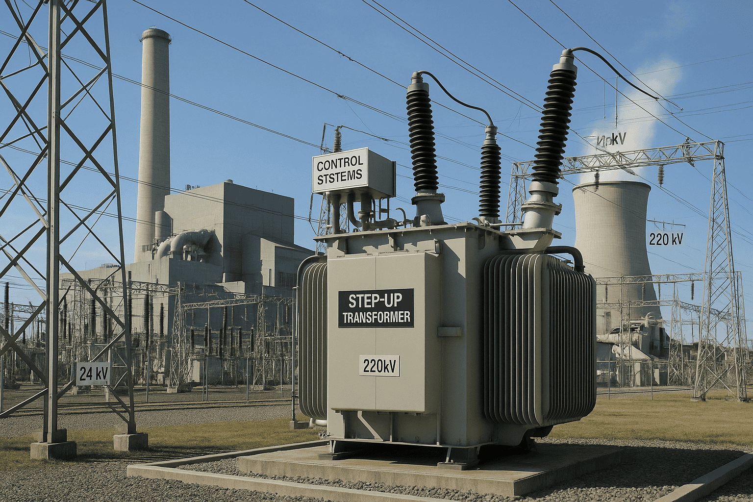
What Is a Three-Phase Transformer and How Is It Constructed?
![]()
Three-phase transformers are the backbone of modern electrical power systems, enabling efficient high-power transmission and distribution in industrial, utility, and renewable networks. They are more compact, economical, and efficient than equivalent banks of single-phase units, and are constructed to handle balanced three-phase loads in a single integrated unit.
A three-phase transformer is an electrical device that converts three-phase AC voltage from one level to another using magnetic induction. It consists of three sets of windings—primary and secondary—either wound on a common core (three limbs) or in three single-phase units interconnected. The windings can be connected in delta or wye configurations to suit grid or load requirements.
Three-phase transformers are indispensable in high-voltage substations, industrial plants, and power generation systems.
Three-phase transformers are just three single-phase units wired together.False
While banks of single-phase transformers can be used, a true three-phase transformer is a single integrated unit with three cores or limbs and shared tank and magnetic path.
Key Construction Elements of a Three-Phase Transformer
| Component | Description |
|---|---|
| Core | Typically three-limb (core type) or five-limb (shell type) laminated magnetic steel |
| Windings | Primary and secondary coils for each phase (A, B, C) |
| Insulation | Between windings, between phases, and between coils and core |
| Tank | Oil-filled for insulation and cooling; houses core and windings |
| Cooling System | Radiators, fans, pumps, and conservator tank for heat management |
| Bushing Terminals | HV and LV connection points for each phase |
| Tap Changer | Off-load or on-load for voltage regulation on HV side |
Typical Winding Configurations (Vector Groups)
| Primary Connection | Secondary Connection | Notation | Use Case |
|---|---|---|---|
| Delta | Wye (Star) | Dyn11 | Distribution transformers |
| Wye | Wye | Yyn0 | Transmission and generator step-up |
| Delta | Delta | Dd0 | Industrial loads, legacy systems |
| Wye | Delta | Yd1 | Motor supply systems |
Vector group affects phase shift, neutral grounding, and fault behavior—always critical in power system design.
Core Construction Types
| Type | Description | Common Applications |
|---|---|---|
| Three-Limb Core-Type | Three vertical limbs with windings, shared top/bottom yoke | Up to 765 kV substations |
| Five-Limb Shell-Type | Central core with return limbs for flux control | Large industrial, furnace units |
| Three-Unit Bank | Three separate single-phase transformers connected externally | Special voltages, maintenance flexibility |
Advantages of Integrated Three-Phase Transformers
| Benefit | Explanation |
|---|---|
| Compact Design | Shared tank, core, and cooling reduce space and material use |
| Cost Efficiency | Cheaper than three single-phase units of equivalent rating |
| Improved Efficiency | Lower core losses and better mutual flux linking |
| Simplified Installation | One unit to install and commission |
| Balanced Load Handling | Ideal for symmetrical industrial and utility loads |
Application Scenarios
| Sector | Typical Use Case |
|---|---|
| Utilities | Grid step-down transformers (220/66 kV, 66/11 kV) |
| Industries | Internal power distribution (33/6.6 kV) |
| Power Generation | Generator step-up transformers (11/132 kV) |
| Renewables | Wind and solar substation feeders (33/0.69 kV) |
Real-World Example – 132/33 kV 50 MVA Three-Phase Transformer
- Core: Three-limb, stacked CRGO core
- Windings: Copper foil, LV in delta, HV in wye
- Cooling: ONAF (forced air radiators)
- Features: Dyn11 vector group, on-load tap changer ±10%
Supplied to regional grid substation; performed with >99% uptime over 8 years, handling critical industrial and residential loads with stability and low losses
Where Are Single-Phase Transformers Typically Used?
Single-phase transformers play a crucial role in localized power transformation, especially in areas and applications where three-phase power is unavailable or unnecessary. Their simple construction, compact size, and cost-effectiveness make them the go-to choice for low-to-medium voltage conversion in numerous settings.
Single-phase transformers are typically used in residential power distribution, rural electrification, low-voltage commercial and lighting circuits, electronic and control systems, medical and laboratory equipment, and standalone renewable energy systems. They step down or step up voltage in AC circuits where only single-phase supply is available or required.
They are vital in delivering stable, usable voltage to millions of end-users worldwide.
Single-phase transformers are only suitable for heavy industrial applications.False
Single-phase transformers are primarily used in residential, commercial, and small industrial or control applications where balanced three-phase power is not required.
Primary Use Categories for Single-Phase Transformers
| Sector | Common Applications | Typical Ratings |
|---|---|---|
| Residential Power | Pole-mounted distribution, 11 kV to 230/120 V supply | 5–100 kVA |
| Rural Electrification | Off-grid farming and village power | 10–50 kVA |
| Commercial Loads | Small office buildings, shops, backup supplies | 5–50 kVA |
| Lighting Systems | Fluorescent, emergency, outdoor LED lighting circuits | 0.5–5 kVA |
| Control Systems | PLCs, relays, sensors in machinery | 0.1–5 kVA |
| Electronics & Labs | Oscilloscopes, test benches, chargers | 50–1000 VA |
| Renewable Systems | Single-phase inverters, battery charging systems | 1–10 kVA |
Installation Settings
| Setting Type | Transformer Example | Description |
|---|---|---|
| Utility Pole-Mounted | 11 kV to 230 V step-down transformer | Used in rural and suburban distribution |
| Indoor Panel Mount | 415 V to 24 V control transformer in factory panels | Provides voltage for contactors/sensors |
| Outdoor Pad-Mount | Enclosed transformers for commercial premises | Low noise, safe access |
| Rack Mount/Test Bench | Compact dry-type transformer for lab use | Isolates sensitive electronics |
Advantages of Single-Phase Transformers in These Applications
| Benefit | Application Value |
|---|---|
| Simple and Cost-Effective | Low-cost solution for small loads |
| Compact Size | Ideal for indoor panels and tight spaces |
| Low Maintenance | Long life, minimal servicing for sealed dry/oil types |
| Availability | Easily sourced, standard voltages for 230 V/120 V circuits |
| High Efficiency at Small Load | Typical efficiency >95% for rated load |
Real-World Use Case – Rural Electrification
- Location: Mountain village, remote area, no grid access
- Installed: 25 kVA, 11/0.23 kV single-phase pole-mount transformer
- Load: 15 homes, school, irrigation pump
- Cooling: Oil-immersed, sealed tank, ONAN cooled
- Outcome: Consistent power delivery with >10 years operation, minimal maintenance, and significant local development impact
Summary Table: Where You’ll Find Single-Phase Transformers
| Application Environment | Typical Load Type | Voltage Range |
|---|---|---|
| Residential Distribution | Lights, appliances, HVAC, sockets | 11 kV → 230/120 V |
| Commercial Offices/Shops | Lighting, point-of-sale, AC units | 415 V → 240 V |
| Machinery Control Panels | Relays, solenoids, sensor interfaces | 415 V → 24/48 V |
| Agricultural Pumps and Lights | Irrigation and shed lighting | 11 kV → 230 V |
| Solar Backup Inverters | Battery charging, inverter feed-in | 230 V ↔ 24–72 V |
| Laboratories/Test Rooms | Power supplies, analyzers, oscilloscopes | 230 V ↔ 12–48 V |
What Are the Primary Applications of Three-Phase Transformers?
Three-phase transformers are foundational to electrical power infrastructure worldwide, enabling the generation, transmission, and utilization of large-scale electricity efficiently and reliably. They are the preferred solution for systems requiring high power delivery, voltage step-up/down, and stable load sharing across three conductors.
The primary applications of three-phase transformers include high-voltage power transmission and distribution, industrial power supply, commercial building systems, data centers, renewable energy grid integration, and large motor or drive loads. These transformers provide balanced three-phase voltage, reduce energy losses, and support efficient bulk power management.
Their usage spans virtually all segments of modern power networks.
Three-phase transformers are rarely used outside of heavy industry.False
Three-phase transformers are widely used in utilities, data centers, hospitals, commercial buildings, and renewable systems—not just in heavy industry.
Core Application Areas
| Sector | Description and Use Case | Typical Rating Range |
|---|---|---|
| Power Transmission | Voltage step-up (e.g., 11/132 kV) from generation to grid | 50–1000+ MVA |
| Power Distribution | Voltage step-down (e.g., 132/33 kV, 33/11 kV) to regional networks | 10–315 MVA |
| Industrial Power | 33/6.6 kV or 11/3.3 kV for steel, chemical, cement, and paper plants | 1–100 MVA |
| Commercial Buildings | Internal building distribution (11/0.4 kV or 415/240 V systems) | 100 kVA–5 MVA |
| Data Centers | Redundant three-phase supply for IT racks, cooling, and UPS systems | 1–20 MVA |
| Hospitals & Airports | Life-critical infrastructure requiring high reliability and power quality | 0.5–10 MVA |
| Renewable Energy | Grid-tied step-up from wind/solar inverters to HV feeders | 1–60 MVA |
| Offshore/Oil Rigs | Explosion-proof, compact three-phase transformers for drives | 0.25–15 MVA |
Key Functional Roles in Power Systems
| Function | Role of Three-Phase Transformers |
|---|---|
| Voltage Transformation | Step up for transmission or step down for usage |
| Load Balancing | Delivers consistent power across three conductors |
| Loss Minimization | Higher efficiency at high power levels |
| Fault Isolation | Supports differential and overcurrent protection schemes |
| System Interconnection | Allows interfacing of networks with different voltage levels |
Typical Installation Examples
| Installation Type | Example Configuration | Transformer Spec Example |
|---|---|---|
| Grid Substation | 220 kV to 66 kV step-down | 250 MVA, ONAN/ONAF, Dyn11 |
| Industrial Feeder | 33 kV to 6.6 kV for rolling mill | 25 MVA, OFAF, YNd1 |
| Building Utility Room | 11 kV to 415 V supply for HVAC, lifts | 1.6 MVA, ONAN, Dyn11 |
| Renewable Substation | 0.69 kV inverter to 33 kV collector | 2.5 MVA, sealed, Dyn5 |
| Power Plant Step-Up | 11 kV generator to 132 kV grid | 90 MVA, OFWF, YNd11 |
Real-World Case Study – Data Center Power Backbone
- Installation: Tier IV data center, 11/0.415 kV transformers in N+1 redundancy
- Load: Server rooms, cooling, security, power conditioning systems
- Features: High efficiency (low-loss), Dyn11 vector group, integrated smart monitoring
- Outcome: Delivered 99.999% uptime power, with real-time load balancing and efficient cooling
Summary Table: Application by Industry
| Industry Sector | Transformer Role | Power Class (Typical) |
|---|---|---|
| Utilities | Transmission/distribution node | 50–1000 MVA |
| Manufacturing | Motor drives, furnaces, internal grids | 5–100 MVA |
| Renewable Energy | Solar/wind collector and grid interface | 1–60 MVA |
| Healthcare | Uninterrupted supply for sensitive equipment | 0.5–5 MVA |
| Transportation (Metro) | Electrified rail, signal stations, stations | 1–25 MVA |
| Data Centers | UPS, HVAC, server infrastructure | 1–20 MVA |
How Do Performance and Efficiency Compare Between Single-Phase and Three-Phase Transformers?
When selecting a transformer type for your application, understanding the differences in performance and efficiency between single-phase and three-phase transformers is crucial. Each type is designed for specific use cases, with inherent characteristics that influence how much power it can handle, how efficiently it operates, and what kind of loads it best supports.
Three-phase transformers generally offer better efficiency, superior load handling, and reduced copper losses compared to single-phase transformers, especially at higher power levels. Single-phase transformers, while simpler and cost-effective for small loads, become inefficient and impractical for large-scale or balanced three-phase power distribution.
Choosing the right type ensures operational cost savings, optimal energy transfer, and appropriate power quality.
Three-phase transformers are always less efficient than single-phase types.False
Three-phase transformers are typically more efficient and compact than single-phase systems of equivalent rating, especially at higher power levels.
Key Differences in Performance & Efficiency
| Criteria | Single-Phase Transformer | Three-Phase Transformer |
|---|---|---|
| Efficiency | 92%–96% at full load | 96%–99.5% at full load |
| Load Type | Unbalanced or single-phase loads | Balanced three-phase loads |
| Copper Losses | Higher due to more winding per kVA | Lower due to better flux utilization |
| Core Usage | Less efficient magnetic flux linkage | Shared core = improved magnetic efficiency |
| Size and Weight (same power) | Heavier and larger | More compact and lighter |
| Power Rating Range | Typically up to 250 kVA | Typically from 100 kVA to 1000+ MVA |
| Cost per Unit Power | Higher at larger kVA | Lower due to scale and construction |
| Voltage Regulation | More variation under load | Tighter voltage control |
| Use in Power Grids | Not common | Industry standard |
| Use in Homes/Control | Preferred for localized use | Not suitable or economical |
Technical Efficiency Comparison (at 100 kVA Load)
| Transformer Type | Core Loss (W) | Copper Loss (W) | Total Loss (W) | Efficiency (%) |
|---|---|---|---|---|
| Single-Phase | 850 | 1200 | 2050 | ~95.0% |
| Three-Phase | 700 | 950 | 1650 | ~96.7% |
Three-phase transformers show lower total loss and higher conversion efficiency, especially above 50 kVA.
Power Handling Capability
| Power Level | Suitable Transformer Type |
|---|---|
| <10 kVA | Single-phase |
| 10–100 kVA | Either (depends on load type) |
| >100 kVA | Three-phase recommended |
| >500 kVA | Three-phase essential |
Application-Based Performance Advantage
| Application Scenario | Preferred Transformer Type | Justification |
|---|---|---|
| Rural house supply | Single-phase | Low cost, low power demand |
| Small commercial outlet | Single-phase | Supports lighting and single-phase appliances |
| Factory motors and HVAC | Three-phase | Balanced load, better startup torque |
| Solar grid tie (utility) | Three-phase | Efficient grid integration |
| Test bench or control panel | Single-phase | Simplicity and compatibility |
| Data center, substation | Three-phase | High capacity, stable performance |
Real-World Use Example – Commercial Warehouse
- Load: Mixed lighting, HVAC, and conveyor motors
- Total demand: 120 kVA
- Compared: 3×40 kVA single-phase vs. 1×120 kVA three-phase
Outcome:
- Three-phase unit had 4.2% higher full-load efficiency
- Lower footprint by 30%
- Easier protection and load balancing
Conclusion: Chose three-phase transformer—lower operating cost and better thermal margin
How to Choose Between a Single-Phase and Three-Phase Transformer?

Choosing between a single-phase and a three-phase transformer is not just a matter of equipment type—it's a decision that affects cost, performance, energy efficiency, and long-term suitability. The ideal transformer must match not only the voltage and power requirements but also the nature of the load, the system configuration, and the future scalability of the application.
To choose between a single-phase and a three-phase transformer, assess the total power demand, type of electrical loads (balanced or unbalanced), availability of supply voltage, application environment, space constraints, and budget. Single-phase transformers are ideal for low-power, localized loads, while three-phase transformers are more efficient and economical for higher power, balanced loads in industrial or utility-scale settings.
Making the right choice ensures safe operation, minimizes energy loss, and aligns with future expansion plans.
Three-phase transformers are always the better choice for every project.False
Single-phase transformers are more suitable for small loads, control circuits, rural supply, and specific residential or commercial installations.
Step-by-Step Selection Criteria
| Selection Factor | Single-Phase Transformer | Three-Phase Transformer |
|---|---|---|
| Power Demand | ≤10–100 kVA | >100 kVA to >1000 MVA |
| Load Type | Unbalanced or single-phase loads | Balanced three-phase motors/equipment |
| Supply System | 1-phase input/output | 3-phase input/output |
| Efficiency Required | Acceptable at low load | Higher efficiency at full load |
| Application | Homes, offices, control panels | Substations, plants, renewables |
| Cost Constraints | Lower initial cost | Lower cost per kVA in high power |
| Footprint Allowed | Smaller for small capacity | More compact for large capacity |
| Installation Location | Pole-mounted or indoors | Pad-mounted or indoor vaults |
Transformer Type Selection Flowchart
Is your available power source single-phase?
✔ Yes → Use Single-Phase Transformer
✖ No → ContinueIs the total load < 15 kVA and mostly single-phase?
✔ Yes → Single-Phase Preferred
✖ No → ContinueAre you powering three-phase motors or balanced loads?
✔ Yes → Use Three-Phase Transformer
✖ No → ContinueDo you need high efficiency and scalability?
✔ Yes → Use Three-Phase Transformer
✖ Yes (low cost, simple load) → Single-Phase May Suffice
Real-World Selection Examples
| Scenario | Transformer Chosen | Reason |
|---|---|---|
| Rural Household Cluster | Single-Phase, 25 kVA | 230 V loads, low cost, single-phase grid |
| Office Complex (urban) | Three-Phase, 250 kVA | Mixed load, HVAC, elevators, balanced use |
| Control Panel for CNC Machine | Single-Phase, 3 kVA | Only sensors, contactors powered |
| Substation Distribution Feeder | Three-Phase, 10 MVA | Supplies three-phase industrial and residential zones |
| Solar Farm Collector Transformer | Three-Phase, 5 MVA | Balanced inverter output, 0.69/33 kV step-up |
Efficiency and Operational Comparison Summary
| Metric | Single-Phase | Three-Phase |
|---|---|---|
| Typical Efficiency | 93–96% | 96–99.5% |
| Total Losses per kVA | Higher | Lower |
| Maintenance Frequency | Low | Moderate (fans, pumps) |
| Scalability | Limited | High |
| Cost per Unit Power | Higher at ≥100 kVA | Lower above 100 kVA |
Common Mistakes to Avoid
- ❌ Using a single-phase transformer for a three-phase motor load
- ❌ Selecting three single-phase transformers without load balancing
- ❌ Ignoring supply voltage configuration (e.g., grid offers only three-phase)
- ❌ Underestimating future load growth that favors three-phase
Conclusion
Single-phase and three-phase transformers serve different but equally important roles in the power distribution landscape. Single-phase transformers are ideal for low-load and household applications, while three-phase transformers are suited for high-power, continuous-load environments like factories and infrastructure grids. Selecting the appropriate type depends on power requirements, system design, and intended application, ensuring optimal performance, safety, and efficiency.
FAQ
Q1: What is the difference between single-phase and three-phase power transformers?
A1: Single-phase transformers have one primary and one secondary winding, handling a single AC waveform.
Three-phase transformers have three sets of windings, supporting three AC waveforms, typically spaced 120° apart.
They differ in load capacity, system compatibility, and application scope.
Q2: Where are single-phase transformers used?
A2: Single-phase transformers are commonly used in:
Residential power distribution (e.g., 120V/240V supply to homes)
Rural and remote areas with low power demand
Lighting and small industrial loads
Electronic and control circuits
They are simpler, cost-effective, and suited for low-capacity systems.
Q3: Where are three-phase transformers used?
A3: Three-phase transformers are typically used in:
Industrial and commercial facilities
Power transmission and substations
Large motors, HVAC systems, and machinery
Urban distribution networks
They offer better efficiency, balanced load sharing, and greater power density, ideal for high-demand applications.
Q4: Can single-phase transformers be used in three-phase systems?
A4: Yes. In a banked configuration, three single-phase transformers can be connected to form a three-phase system (open-delta or wye-delta setup). However, using a three-phase transformer unit is more:
Compact
Efficient
Easier to install and maintain
for most industrial and utility settings.
Q5: How do you choose between single-phase and three-phase transformers?
A5: Choose based on:
Load type and size: Heavy industrial vs light residential
Power system design: Three-phase grid or single-phase service
Cost and infrastructure: Initial cost, space, and installation needs
Future scalability: Expandability and system compatibility
Three-phase transformers are ideal for modern grids and industries, while single-phase is best for localized, lower-demand areas.
References
"Single vs Three Phase Transformers Explained" – https://www.electrical4u.com/single-phase-vs-three-phase-transformer
"IEEE C57 Standards for Transformer Phases" – https://ieeexplore.ieee.org/document/9054962
"NREL: Electrical Infrastructure Planning for Transformers" – https://www.nrel.gov/docs/single-vs-three-phase-transformers.pdf
"Doble: Transformer Phase Configuration and Application" – https://www.doble.com/single-vs-three-phase-transformer-design
"ScienceDirect: Comparative Study of Transformer Phases" – https://www.sciencedirect.com/single-vs-three-phase-transformer-analysis