Power transformers are critical components in energy transmission systems. While built to be robust and reliable, they are still vulnerable to various faults caused by electrical, mechanical, thermal, or environmental stress. Early identification of these faults is essential to avoid catastrophic failures, reduce downtime, and extend the transformer's operational life. This guide outlines how to recognize and interpret signs of transformer malfunctions using visual inspections, monitoring tools, and diagnostic testing.
What Are the Most Common Faults in Power Transformers?
Power transformers are engineered for decades of reliable service, but they are not immune to electrical, mechanical, thermal, and chemical stresses. Over time, these stresses can lead to a range of faults, some developing gradually and others striking suddenly with catastrophic consequences. Understanding the most common faults in power transformers allows operators to implement predictive maintenance, targeted monitoring, and design improvements—dramatically reducing downtime and extending asset life.
The most common faults in power transformers include winding short circuits, insulation degradation, overheating of windings or core, bushing failure, oil contamination or leakage, tap changer malfunctions, and core or clamp issues. These faults result from overloading, aging, moisture ingress, poor connections, or transient surges and can lead to severe failure if not detected early.
Proper diagnostics, condition monitoring, and regular testing can help identify and mitigate these faults before they escalate.
Power transformers rarely fail and do not have common fault patterns.False
Power transformers fail due to identifiable fault types such as insulation breakdown, overheating, and winding shorts. Understanding these patterns is key to prevention.
Top 8 Most Common Transformer Faults
| Fault Type | Description & Consequences |
|---|---|
| 1. Winding Short Circuit | Turn-to-turn or phase-to-phase fault due to insulation breakdown |
| 2. Insulation Degradation | Caused by heat, moisture, or chemical aging; leads to dielectric failure |
| 3. Overheating (Hotspots) | Localized thermal stress causes accelerated aging and partial discharge |
| 4. Bushing Failure | Cracks, contamination, or flashover leads to high-voltage arcing |
| 5. Tap Changer Faults | Arcing, wear, or oil contamination in OLTC units |
| 6. Oil Contamination/Leakage | Reduces dielectric strength, increases fire risk |
| 7. Core/Clamp Issues | Loosening or insulation failure causes vibration, heating, or circulating currents |
| 8. Partial Discharge (PD) | Early-stage insulation breakdown detected as local ionization |
Fault Detection by Symptom and Test
| Symptom | Likely Fault | Diagnostic Tool |
|---|---|---|
| Burning smell + hot radiators | Overheating, insulation aging | IR camera, DGA, temperature sensor |
| Irregular sound or buzzing | Core vibration, winding looseness | Acoustic sensor, vibration probe |
| Sudden trip, no external signs | Internal winding short | Winding resistance, TTR, relay logs |
| Visible oil leak | Seal degradation, tank corrosion | Visual inspection, oil sample |
| Corona noise or flashing | Bushing PD or contamination | UV camera, partial discharge test |
| Load voltage instability | Tap changer contact wear | OLTC analyzer, voltage log |
Real-World Case – Multiple Faults in One Unit
- Transformer: 40 MVA, 132/33 kV unit
- Event: Relay trip, overheating alarm, unusual noise
Findings:
- DGA: Elevated CO, C₂H₄, acetylene → overheating + arc
- IR test: Degraded paper insulation in LV winding
- Visual: Bushing crack and oil leakage near tap
- Root Cause: Combined overload, moisture ingress, bushing deterioration
Solution: Partial coil rewrapping, bushing replacement, oil purification, and tap changer overhaul
Frequency of Fault Types by Failure Statistics
| Fault Type | % of Total Transformer Failures (Typical Utility Data) |
|---|---|
| Winding Short Circuits | 35–45% |
| Bushing Flashover/Failure | 15–25% |
| Tap Changer Malfunction | 10–15% |
| Overheating/Hotspots | 10–12% |
| Oil-Related Issues | 8–10% |
| Core and Structural | 2–5% |
Causes Behind Common Transformer Faults
| Fault Category | Underlying Causes |
|---|---|
| Electrical Faults | Lightning, overvoltage, switching surge, poor connections |
| Thermal Faults | Overloading, blocked cooling, radiator failure |
| Chemical Faults | Oxidized oil, sludge, moisture ingress |
| Mechanical Faults | Loosened winding clamps, shipping damage |
| Operational Faults | Incorrect tap settings, neglected maintenance |
Prevention and Early Detection Measures
| Monitoring/Test Tool | Fault Prevented/Detected |
|---|---|
| Dissolved Gas Analysis (DGA) | Internal arcs, overheating, insulation breakdown |
| Furan & Moisture Testing | Paper aging, water ingress |
| IR Thermography | Hotspots, load imbalance |
| Online PD Sensors | Partial discharge detection |
| Tap Changer Analyzer | OLTC timing/contact wear |
| Routine Oil Sampling | Acidity, sludge, moisture, metal particles |
| Relay and SCADA Review | Early tripping and transient patterns |
What Visual and Audible Symptoms Indicate a Potential Transformer Fault?
Before transformers fail completely, they often exhibit warning signs detectable by sight and sound. Trained operators and maintenance personnel can identify early-stage faults by recognizing abnormal visual or acoustic patterns. These symptoms are not just superficial—they typically point to underlying electrical, thermal, or mechanical problems, including insulation failure, partial discharge, bushing degradation, or winding stress. Prompt action when these cues appear can prevent catastrophic failure.
Visual and audible symptoms of potential transformer faults include smoke or steam, oil leaks, abnormal sounds such as buzzing, popping, or humming, arcing flashes, bushing discoloration, excessive heating, and strong burnt or chemical odors. These indicators suggest internal or external electrical stress, insulation breakdown, or mechanical instability and warrant immediate inspection.
Identifying these symptoms early is essential for prevention, protection, and equipment longevity.
Transformer faults develop silently and without noticeable signs.False
Transformer faults are often preceded by audible and visual symptoms such as humming, arcing, smoke, or oil leaks, which provide early opportunities for detection and response.
Common Visual Symptoms of Transformer Faults
| Visual Indicator | Potential Cause |
|---|---|
| Smoke or Steam Emission | Overheating, internal arcing, oil breakdown |
| Oil Leakage | Damaged seals, corroded tank, overpressure rupture |
| Discoloration (Bushing or Paint) | Thermal hotspots, arcing, flashover |
| Burn Marks or Soot | Past fault, surface tracking, PD damage |
| Bubbling Oil in Conservator | Internal gassing, moisture ingress |
| Flashing or Sparks at Terminals | Live arcing, poor contact, insulation failure |
| Drooping Cables or Bulging Cover | Mechanical stress, pressure from gas buildup |
| Loose or Disconnected Ground Wires | Potential shock hazard and lightning vulnerability |
Audible Symptoms and What They May Indicate
| Sound Type | Interpretation |
|---|---|
| Loud Buzzing or Humming | Core saturation, unbalanced load, or magnetic vibration |
| Crackling or Popping | Partial discharge, moisture in insulation |
| High-Pitched Whining | Resonance in windings or tap changer instability |
| Sudden “Bang” or Explosion | Short circuit, arc flash, tank rupture |
| Clicking During Load Changes | Tap changer switching problems |
| Persistent Rattling | Loosened clamps, loose core, vibration from unbalanced magnetic forces |
Symptom-to-Fault Mapping Guide
| Symptom Observed | Likely Fault Candidate |
|---|---|
| Smoke from bushing | Bushing crack, insulation flashover |
| Oil puddle beneath tank | Gasket failure, impact damage, pressure burst |
| Loud hum growing over time | Core clamp loosening, harmonic distortion, overvoltage |
| Crackling inside unit | PD due to wet insulation or air pockets |
| Blackened enclosure paint | External arcing, excessive internal temperature |
| Rising top oil thermometer | Cooling failure, winding overload |
Example Field Scenario
- Equipment: 1 MVA oil-filled transformer
Symptoms:
- Buzzing grew louder over a week
- Operator noticed burnt smell near bushing
- IR camera showed one side of the tank was 18 °C hotter
- Oil test revealed 46 ppm moisture and CO₂ rise in DGA
- Action: Transformer taken offline and breather/gasket replaced
Outcome: Averted potential failure—early symptoms enabled safe intervention
Diagnostic Tools to Confirm Visual and Audible Faults
| Tool | What It Confirms |
|---|---|
| Thermal Imaging (IR) | Detects uneven heat zones, hotspots, bushing failure |
| Ultrasonic/Acoustic Detectors | Captures PD, arcing, internal corona |
| Oil Sampling Kit | Assesses moisture, acidity, gas evolution |
| Sound Level Meter | Logs audible transformer vibration profiles |
| Vibration Analyzer | Detects mechanical instability in core or clamps |
| DGA Test Set | Reveals fault gas buildup linked to observed symptoms |
What to Do if Visual or Audible Symptoms Are Detected
| Action Step | Why It’s Critical |
|---|---|
| Isolate Power or Reduce Load | Prevent fault escalation |
| Inform Maintenance Immediately | Begin tests and inspections before failure |
| Log Observations | Photos, sound recordings, thermal scans assist in diagnostics |
| Inspect Oil and Relays | Confirm if stress is internal or external |
| Do Not Ignore Repeating Symptoms | Recurring noise or leaks may precede insulation collapse |
How Can Oil Testing Help Detect Internal Problems in Power Transformers?
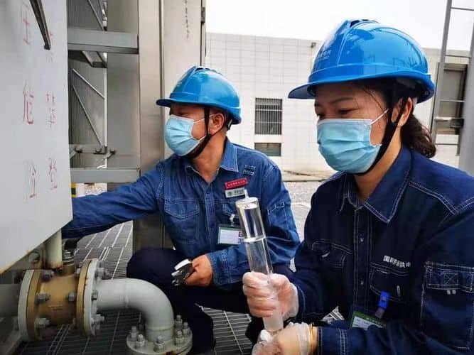
Oil testing is the most effective non-invasive method for detecting internal problems in oil-immersed transformers. The transformer oil serves not only as a coolant and dielectric medium, but also as a diagnostic medium—retaining chemical fingerprints of internal faults. By periodically analyzing oil samples, operators can identify emerging issues such as insulation degradation, overheating, arcing, and contamination, often before any visible or audible symptoms occur.
Transformer oil testing helps detect internal problems by measuring dissolved gases from electrical and thermal faults, identifying moisture and furanic compounds from insulation aging, assessing dielectric strength, and detecting contamination. Key methods include DGA (Dissolved Gas Analysis), Karl Fischer moisture testing, acidity testing, BDV (Breakdown Voltage) measurement, and furan analysis.
Regular oil testing is central to condition-based maintenance and failure prevention strategies.
Transformer oil testing only provides information about oil quality, not equipment health.False
Transformer oil testing reveals critical information about internal electrical, thermal, and insulation conditions through gas analysis, moisture content, and chemical degradation markers.
Core Oil Tests and the Internal Problems They Reveal
| Test Name | Detects or Indicates |
|---|---|
| Dissolved Gas Analysis (DGA) | Arcing, overheating, insulation breakdown, partial discharge |
| Moisture (Karl Fischer) | Seal failure, water ingress, paper insulation deterioration |
| Furan Analysis | Thermal aging and hydrolysis of cellulose insulation |
| BDV (Breakdown Voltage) | Dielectric strength and oil cleanliness |
| Acidity (Neutralization Number) | Oxidation, sludge formation, aging oil |
| Interfacial Tension (IFT) | Oil contamination or polar compound buildup |
| Color/Appearance Check | Emulsion, suspended solids, oil oxidation |
Fault Signature Gases in DGA and Their Meaning
| Gas Type | Fault Indicated | Typical Cause |
|---|---|---|
| Hydrogen (H₂) | Partial discharge | Air pockets, insulation voids |
| Methane (CH₄) | Low-energy thermal fault | Minor hotspots |
| Ethane/Ethylene (C₂H₆/C₂H₄) | Thermal overheating | Hot metal, overloading |
| Acetylene (C₂H₂) | Arcing or high-energy discharges | Internal arcing |
| Carbon Monoxide/Dioxide (CO/CO₂) | Cellulose insulation degradation | Thermal aging or wet paper |
Interpreting Moisture and Furan Levels
| Parameter | What It Tells You |
|---|---|
| Moisture in Oil (>35 ppm) | Indicates seal leakage, water ingress, or wet paper |
| Paper Moisture >2% | Severe degradation risk for insulation |
| Furan Content >1 mg/L | Advanced thermal aging of cellulose paper insulation |
| Rapid Furan Rise | May indicate recent overheating event or loss of drying |
Example Case – Early Detection via Oil Testing
- Transformer: 10 MVA, 66/11 kV distribution unit
Annual oil test results:
- H₂ = 180 ppm, C₂H₂ = 45 ppm → arcing suspected
- Furan = 0.9 mg/L (up from 0.4)
- Moisture = 58 ppm
Action Taken:
- Internal inspection revealed failing OLTC contacts
- Replaced OLTC unit before full winding flashover
Result: Prevented \$70,000 transformer failure through timely oil diagnostics
Oil Test Intervals and Guidelines (Per Standards)
| Transformer Class | Suggested Oil Testing Frequency |
|---|---|
| ≤1 MVA (Small) | Every 2–3 years |
| 1–10 MVA (Medium) | Annually |
| >10 MVA or Critical Units | Twice per year, DGA quarterly recommended |
| After Any Event or Overload | Immediate oil sampling |
Integration with Condition-Based Monitoring (CBM)
| Oil Test Input | Maintenance Action Triggered |
|---|---|
| High Moisture Trend | Dehydration or seal replacement |
| Elevated DGA Gases | Internal inspection or load reduction |
| Low BDV (<40 kV) | Oil filtration or full replacement |
| Furan Spike | Reassess insulation age, possibly derate transformer |
Key Advantages of Regular Oil Testing
- Non-invasive: No need to open the transformer
- Predictive: Faults detected long before visible failure
- Cost-saving: Helps avoid major damage and unscheduled outages
- Trending: Identifies gradual deterioration via time-series data
- Warranty Support: Documents operating condition for OEM consultation
What Electrical Tests Are Used for Fault Diagnosis in Power Transformers?
While oil analysis reveals chemical and thermal signs of transformer distress, electrical tests are essential for identifying mechanical damage, insulation breakdown, winding faults, and terminal degradation. These tests are performed both periodically for preventive maintenance and after incidents for fault diagnosis. Electrical test results provide direct insight into the integrity of windings, cores, insulation systems, and magnetic balance, guiding decisions on repair, refurbishment, or replacement.
The key electrical tests used for transformer fault diagnosis include insulation resistance (IR), polarization index (PI), winding resistance, transformer turns ratio (TTR), short-circuit impedance, capacitance and dissipation factor (Tan Delta), and applied or induced voltage withstand tests. These tests reveal internal faults such as insulation aging, winding deformation, contact wear, and magnetic imbalances.
Together, they form the foundation of electrical condition assessment for transformers of all sizes.
Transformer faults cannot be detected using electrical tests.False
Electrical tests like insulation resistance, winding resistance, and TTR are essential tools for identifying internal faults, aging, and failures in transformer components.
Core Electrical Diagnostic Tests and What They Detect
| Test Name | Purpose & Faults Identified |
|---|---|
| Insulation Resistance (IR) | Detects insulation aging, contamination, or moisture ingress |
| Polarization Index (PI) | Assesses insulation health over time using IR time ratio |
| Winding Resistance Test | Identifies open circuits, shorted turns, or poor connections |
| Transformer Turns Ratio (TTR) | Detects winding deformation, tap changer faults |
| Capacitance & Tan Delta | Measures insulation loss and paper degradation in bushings or windings |
| Short-Circuit Impedance | Reveals winding shifts or core displacement from short circuits |
| AC/DC Hipot Test | Confirms high-voltage dielectric strength |
| Sweep Frequency Response (SFRA) | Detects mechanical displacement in core/windings |
Common Faults Diagnosed by Each Test
| Fault Type | Best Detection Test(s) |
|---|---|
| Moist or Aged Insulation | IR, PI, Tan Delta |
| Loose/Burnt Windings | Winding Resistance, SFRA |
| Tap Changer Defects | TTR, Contact Resistance |
| Partial Discharge Risk | IR, DGA, Tan Delta |
| Core/Winding Displacement | SFRA, Impedance Test |
| Poor Grounding or Arcing Path | IR (core-to-ground), Capacitance Tests |
Real-World Example – Electrical Tests Uncover Hidden Fault
- Transformer: 20 MVA, 132/33 kV power unit
- Trigger: Tripped during switching, no oil or visual issues
Test Results:
- IR: 120 MΩ (acceptable)
- TTR: 1.98 vs 2.00 expected → minor imbalance
- Winding Resistance: HV-A phase 15% higher
- SFRA: Shift in 1 kHz–10 kHz band → winding distortion
- Conclusion: Windings shifted during short circuit, causing imbalance
Outcome: Rewind performed; insulation verified and returned to service
Electrical Testing Frequency Guidelines
| Transformer Type / Class | Recommended Test Intervals |
|---|---|
| <1 MVA Distribution Units | IR & TTR every 2–3 years |
| 1–20 MVA Industrial Units | IR, TTR, Resistance annually; Tan Delta every 3 years |
| >20 MVA or Critical Infrastructure | Full suite of tests annually or post-fault |
| After Transport, Shock, or Failure | IR, SFRA, TTR, Resistance, Hipot, and Oil tests |
Testing Equipment Used and Their Function
| Equipment | Measurement Function |
|---|---|
| Megger IR Tester (1–5 kV) | Insulation resistance phase-to-phase/ground |
| Digital TTR Meter | Turn ratio across winding pairs/taps |
| Micro-ohmmeter | Winding resistance and contact resistance |
| Tan Delta & Capacitance Set | Measures dielectric losses and insulation aging |
| SFRA Analyzer | Frequency response showing mechanical integrity |
| Hipot Tester (AC/DC) | Withstand voltage test for insulation breakdown strength |
Interpretation of Typical Test Results
| Test Parameter | Good Condition Value | Action Threshold/Concern |
|---|---|---|
| IR (Phase-Phase) | >500 MΩ | <100 MΩ: Investigate moisture/age |
| PI (10-min/1-min ratio) | >2.0 | <1.3: Possible contamination/degradation |
| Winding Resistance Balance | <2% deviation across phases | >5% deviation: Check for joint/burn |
| TTR Ratio Error | <0.5% vs. nameplate | >1%: Suspect tap or winding issue |
| Tan Delta (HV winding) | <0.5% | >1.0%: Sign of insulation aging |
How Does Online Monitoring Detect Emerging Faults in Power Transformers?
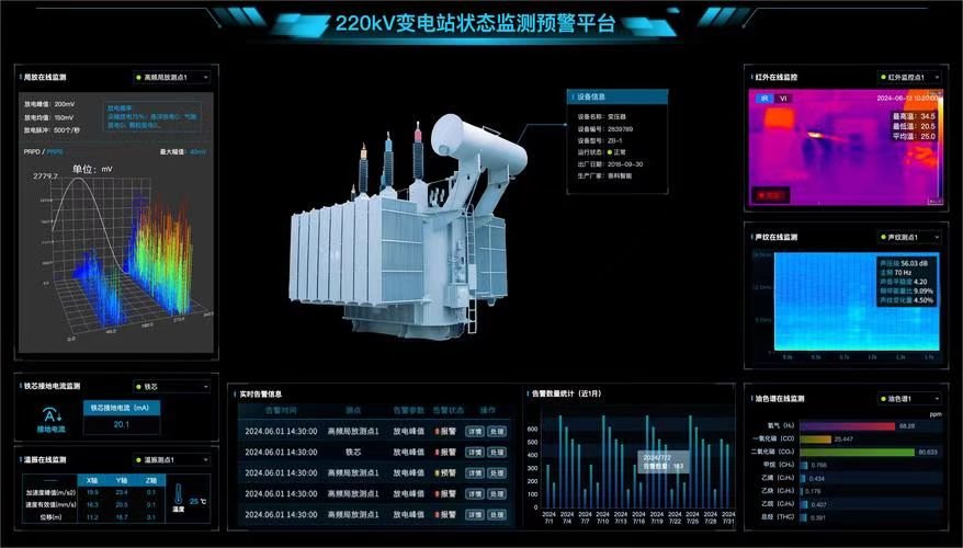
In modern power systems, transformer failure is too costly to wait for symptoms. That’s where online monitoring systems come in. These advanced technologies use real-time sensor data to detect the earliest signs of failure—before physical symptoms or test intervals arrive. Online monitoring allows operators to act proactively, rather than reactively, by identifying trends in temperature, oil quality, gas generation, vibration, or partial discharge that indicate developing faults.
Online monitoring detects emerging faults in transformers by continuously measuring key parameters like temperature, dissolved gases, moisture, bushing health, partial discharge, and loading conditions. By using intelligent analytics and alert thresholds, these systems identify insulation degradation, overheating, incipient arcing, and mechanical stress before visible failure occurs.
This continuous insight helps utilities optimize maintenance, extend asset life, and avoid outages.
Transformer faults always require manual testing to detect.False
Online monitoring systems continuously track critical parameters and can detect emerging transformer faults earlier than periodic manual tests.
Key Parameters Monitored and Faults Detected
| Parameter | What It Detects |
|---|---|
| Top Oil Temperature | Overheating, cooling system failure |
| Winding Hot Spot | Thermal aging, load imbalance |
| Dissolved Gas Analysis (Online DGA) | Arcing, overheating, insulation decomposition |
| Moisture in Oil | Seal failure, internal humidity rise, insulation risk |
| Partial Discharge (PD) | Insulation voids, surface tracking, early dielectric failure |
| Bushing Capacitance/Tan Delta | Bushing insulation aging or moisture ingress |
| Load Current and Voltage | Load stress patterns, harmonics, phase imbalance |
| Core Ground Current | Core insulation breakdown, circulating current risk |
How Online Systems Work
| Component | Function |
|---|---|
| Sensors Installed on Transformer | Measure physical, thermal, electrical, and chemical data |
| Data Logger or RTU | Collects and timestamps data locally |
| Communication Module (IoT/SCADA) | Sends data to central dashboard or cloud platform |
| Analytics Engine | Applies thresholds, AI models, and trending analysis |
| Alarm & Notification System | Alerts operators if abnormal conditions develop |
| Dashboard Interface | Enables real-time review, trend visualization, and fault history |
Real-World Fault Detection Example
- Transformer: 63 MVA, 132/33 kV substation unit
- Online DGA system triggered C₂H₂ rise from 6 ppm to 43 ppm in 7 days
- Alarm sent to SCADA, triggering inspection
- IR scan confirmed hot spot near OLTC compartment
- Diagnosis: Arcing in diverter switch
- Action: Repaired OLTC before full breakdown
Saved: $250,000+ in potential transformer damage and weeks of grid downtime
Benefits of Online Monitoring Over Offline Testing
| Feature | Online Monitoring | Offline Testing |
|---|---|---|
| Frequency | Continuous (24/7) | Scheduled (e.g., yearly, quarterly) |
| Early Fault Detection | Days to weeks before failure | May miss between-test faults |
| Data Trends | Real-time trending and prediction | Point-in-time results only |
| Response Speed | Immediate alerts | Dependent on test scheduling |
| Operator Dependence | Automated | Requires manual crew deployment |
Most Common Faults Detected Early by Online Systems
| Fault Category | Indicator Picked Up by System |
|---|---|
| Thermal Overload | High winding hot spot, accelerated oil aging |
| Internal Arcing | Sharp acetylene rise in DGA |
| Moisture Ingress | Rising ppm in oil moisture sensor |
| Bushing Degradation | Increase in capacitance, tan delta drift |
| Partial Discharge | Spike in PD pulse count or localization shift |
| Cooling Failure | Top oil rise without load increase |
Online Monitoring System Options
| System Type | Monitored Features | Best For |
|---|---|---|
| Single Gas Monitor | Hydrogen (H₂) only | Compact transformers, critical alerting |
| Multi-Gas Online DGA | 5 or 9 fault gases | Power transformers, mission-critical sites |
| Smart Bushing Monitor | Capacitance, Tan Delta, leakage current | Older or high-voltage bushings |
| Thermal Monitoring System | Hot spot and radiator temp | High-load industrial units |
| Integrated Monitoring Package | All key sensors + SCADA/IoT | Centralized utilities and grid operators |
Integration with Predictive Maintenance
| Function | Impact on Asset Management |
|---|---|
| Condition Indexing | Assigns health score to prioritize interventions |
| Failure Trend Mapping | Tracks abnormal changes across fleet units |
| Risk-Based Maintenance | Plans service based on actual condition, not calendar |
| Lifecycle Optimization | Delays unnecessary replacements while avoiding blind risks |
When Should You Conduct a Detailed Inspection or Shutdown of a Power Transformer?
In transformer maintenance, timing is everything. Waiting too long to inspect or shut down a compromised transformer can lead to catastrophic failure, while shutting down too early or too often disrupts operations unnecessarily. Therefore, utilities and operators must follow evidence-based criteria—triggered by sensor alerts, test results, or behavioral anomalies—to determine when to perform a detailed inspection or a complete shutdown. The decision should balance operational continuity with risk mitigation.
You should conduct a detailed inspection or shutdown of a power transformer when critical indicators are breached—such as abnormal DGA results, insulation resistance drop, visible oil leaks or smoke, rising partial discharge levels, overheating, protection relay trips, or repeated SCADA alarms. Post-event inspections are also mandatory after faults, overloads, or severe environmental conditions.
These events suggest internal deterioration or immediate safety risk and warrant thorough intervention.
Transformer shutdowns should only occur after visible damage is confirmed.False
Shutdowns may be necessary before visible damage occurs, based on predictive data like gas trends, moisture levels, or abnormal temperatures that indicate high failure risk.
Primary Conditions That Warrant Immediate Shutdown
| Trigger Condition | Why It Requires Shutdown |
|---|---|
| DGA Shows Acetylene >35 ppm | Indicates arcing—shutdown avoids escalation |
| Top Oil Temp >90 °C Under Nominal Load | Suggests cooling failure or core overheating |
| IR Drop Below 100 MΩ | Insulation failure risk—immediate isolation required |
| Moisture in Oil >60 ppm | Breakdown voltage dangerously low—fault imminent |
| Multiple Relay Trips Within 24 Hours | Indicates internal instability or flashover |
| Visible Smoke, Oil Leak, or Flashing | Signals failure is already underway |
| High Bushing Capacitance Change (>2%) | Potential flashover risk at HV bushings |
Conditions That Require Scheduled Detailed Inspection (Not Immediate Shutdown)
| Condition | Action Timeline |
|---|---|
| Rising DGA gases (slow rate) | Schedule inspection within 1–2 weeks |
| Unexplained Voltage Fluctuation | Investigate grounding and tap changers within 1 week |
| Tap Changer Contact Wear | OLTC inspection/replacement every 25,000 operations or 3–5 years |
| Periodic IR or PI Test Trend Drop | Conduct internal visual inspection at next maintenance cycle |
| Tan Delta Increase >50% from Baseline | Plan for insulation integrity check within maintenance window |
| Core Ground Current Drift | May indicate insulation breach; inspect within 1–2 weeks |
Real-World Shutdown Decision Example
- Transformer: 10 MVA, 33/11 kV
Online Monitoring:
- C₂H₂ = 42 ppm, H₂ = 125 ppm
- Hot spot temperature rising
- Action: Scheduled shutdown and inspection
- Findings: Arc pitting inside diverter switch and degraded paper insulation
Result: Shut down avoided explosion; unit refurbished and returned safely
Consequences of Delayed Shutdown or Inspection
| Delayed Action Leads To… | Consequence |
|---|---|
| Ignoring gas alarms | Insulation breakdown, tank rupture, arc flash |
| Operating with low IR | Unexpected tripping or flashover during switching |
| Ignoring moisture or BDV alerts | Paper aging, partial discharge, and eventual winding failure |
| Skipping tap changer inspection | Contact burning, voltage instability, internal arc risk |
| Overheating allowed to continue | Accelerated oil oxidation, varnish formation, loss of cooling |
Shutdown Risk Criteria – Use With Predictive Maintenance
| Diagnostic Alert | Severity Threshold (Action Point) |
|---|---|
| C₂H₂ (Acetylene) | >35 ppm: Immediate shutdown |
| H₂ (Hydrogen) | >250 ppm: Inspect within days |
| PI Ratio | <1.3: Schedule detailed internal check |
| Bushing Tan Delta (Δ)>0.5% | Schedule inspection and replace if trending up |
| IR Drop >60% in One Year | Schedule de-energized full test within 30 days |
| Noise/Smell Observed by Staff | Trigger visual and thermal check |
Tools and Processes for Scheduled Inspection
| Inspection Task | Tools Used |
|---|---|
| Thermal Imaging | Detect hot spots and cooling imbalance |
| Visual & Bushing Check | Identify cracks, oil marks, discoloration |
| DGA & Moisture Testing | Confirm gas rates and water risk |
| Tap Changer Timing & Contact Test | Prevent switch failures |
| IR & Winding Resistance | Assess insulation and winding health |
| Oil Leak Test (Static Pressure) | Identify tank, seal, or conservator breaches |
Conclusion
Timely identification of transformer faults is a cornerstone of safe and reliable power system operation. By recognizing physical symptoms, conducting routine oil and electrical tests, and leveraging modern monitoring technologies, engineers can detect issues long before they escalate. A proactive approach to fault detection not only prevents failure but also enhances performance, safety, and cost efficiency over the transformer's lifecycle.
FAQ
Q1: What are the most common faults in power transformers?
A1: Typical transformer faults include:
Overheating of windings or oil
Insulation breakdown due to aging or moisture
Winding short circuits or open circuits
Core grounding faults
Tap changer failures
Oil leaks or contamination
These issues can lead to reduced efficiency, shutdowns, or catastrophic failure if not addressed early.
Q2: What are the visual signs of a transformer fault?
A2: Visual inspection may reveal:
Oil leakage or discolored/burnt oil
Swollen or deformed tank (pressure buildup)
Scorch marks, cracks, or broken bushings
Noise or vibration indicating loose components
Such indicators should trigger immediate diagnostics.
Q3: What tests are used to detect internal transformer faults?
A3: Key diagnostic methods include:
Dissolved Gas Analysis (DGA): Detects gases from insulation/oil degradation
Insulation Resistance (IR) Test: Identifies weakened insulation
Sweep Frequency Response Analysis (SFRA): Detects mechanical deformation
Winding Resistance and TTR Tests: Identify winding issues or tap changer faults
Thermal Imaging: Spots overheating zones
Q4: What causes insulation failure in power transformers?
A4: Main causes include:
Moisture ingress from poor sealing or breather failure
Excessive thermal stress from overloading
Chemical aging of oil and paper
Partial discharges or corona activity in high-voltage zones
Insulation failure leads to internal arcing and flashovers if left unchecked.
Q5: How can transformer faults be prevented or minimized?
A5: Prevention strategies:
Regular maintenance and oil testing
Online monitoring systems for temperature, gas, and partial discharges
Timely repair or replacement of worn parts (gaskets, bushings)
Surge protection and fault relays
Early detection and response are key to avoiding major failures and extending transformer life.
References
"Common Transformer Faults and Diagnosis" – https://www.electrical4u.com/common-transformer-faults
"IEEE C57.104: Guide for DGA Interpretation" – https://ieeexplore.ieee.org/document/8919446
"Doble: Transformer Condition Assessment Tools" – https://www.doble.com/transformer-diagnostics
"NREL: Transformer Fault Prevention and Detection Guide" – https://www.nrel.gov/docs/fy22ost/transformer-fault-guide.pdf
"ScienceDirect: Analysis of Transformer Fault Signatures" – https://www.sciencedirect.com/transformer-fault-pattern-analysis

