Dry-type transformers are known for their safety, low maintenance, and suitability for indoor or environmentally sensitive applications. Unlike oil-immersed transformers, they use air or resin insulation instead of liquid, which makes them more robust in certain conditions. Understanding their expected service life helps facility managers, engineers, and planners make informed decisions about asset management and lifecycle cost optimization.
What Is the Typical Lifespan of a Dry-Type Transformer?
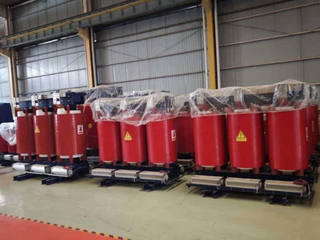
Dry-type transformers—known for their air-insulated windings, low fire risk, and indoor suitability—are commonly used in commercial, institutional, and industrial applications. While they lack the cooling benefits of oil-immersed types, they excel in safety and ease of installation. But how long do they actually last? And what factors determine their longevity?
The typical lifespan of a dry-type transformer is 20 to 30 years under normal conditions, with some units lasting up to 40 years or more when properly sized, ventilated, and maintained. Lifespan is primarily influenced by thermal aging of insulation, overloading frequency, environmental conditions, and dust or moisture exposure.
With correct installation, load management, and periodic cleaning, dry-type transformers offer reliable performance over decades.
Dry-type transformers typically last less than 15 years.False
Most dry-type transformers have a service life of 20–30 years, and can exceed 40 years with proper maintenance and environmental control.
Factors That Define Dry-Type Transformer Lifespan
| Factor | Influence on Service Life |
|---|---|
| Insulation Class (B, F, H) | Determines thermal limit and aging rate |
| Operating Temperature | Above-rated heat drastically reduces insulation life |
| Load Profile | Overloading accelerates degradation |
| Ambient Conditions | Dust, humidity, corrosive gases shorten insulation lifespan |
| Ventilation & Cooling | Poor air flow leads to thermal stress |
| Maintenance Frequency | Cleaning and tightening reduce aging risks |
| Mechanical Stresses | Inrush currents and vibration loosen windings over time |
Typical Lifespan by Insulation System
| Insulation Class | Max Temp (°C) | Estimated Lifespan at Rated Load |
|---|---|---|
| Class B | 130 °C | 20–25 years |
| Class F | 155 °C | 25–30 years |
| Class H | 180 °C | 30–40 years |
Operating below insulation limits extends lifespan; each 10 °C reduction in hot spot temp doubles insulation life.
Expected Service Life by Application Type
| Application Environment | Typical Lifespan (Years) | Notes |
|---|---|---|
| Indoor Clean Utility Room | 30–40+ years | Ideal conditions; minimal stress |
| Industrial Plant (Moderate) | 25–30 years | Ventilation and dust control required |
| Data Centers | 20–25 years | High cycling; temperature must be managed |
| Marine/Mining/Harsh | 15–20 years | Needs high-grade resin and sealing protection |
Signs of Aging in Dry-Type Transformers
| Aging Symptom | Interpretation |
|---|---|
| Discolored or brittle resin | Thermal aging of insulation |
| Cracks in winding coating | Mechanical or thermal stress |
| Dust/dirt accumulation | Reduces convection cooling efficiency |
| Insulation resistance drop | Moisture ingress or insulation deterioration |
| Unusual humming or vibration | Loose windings or core clamps |
Key Maintenance Practices That Extend Life
| Maintenance Task | Frequency | Life Extension Effect |
|---|---|---|
| Visual Inspection | Quarterly/Annually | Identifies early mechanical or thermal damage |
| Dust Cleaning (Blowing/Vacuum) | Every 6–12 months | Prevents overheating, maintains ventilation |
| IR & PI Testing | Every 2–3 years | Detects insulation degradation |
| Winding Tightness Check | Every 3–5 years | Prevents vibration-related failures |
| Thermal Scan/Monitoring | Annually | Identifies overload or imbalance conditions |
Preventive maintenance helps dry-type transformers reach or exceed 30+ years of safe service.
Temperature and Lifespan Relationship – Example
| Hot Spot Temp (°C) | Estimated Life (Years) |
|---|---|
| 120 °C | ~40 years |
| 130 °C | ~30 years |
| 140 °C | ~20 years |
| 160 °C | ~10–15 years |
Follow IEEE C57.96 and IEC 60076-11 for derating recommendations under high temp.
Real-World Lifespan Examples
| Location & Use Case | Transformer Size & Type | Years in Service |
|---|---|---|
| Commercial Office, Europe | 1000 kVA, Class F, indoor | 32 years |
| Hospital, Middle East | 1250 kVA, Class H, air-cooled | 27 years |
| Cement Plant, India | 2000 kVA, epoxy cast | 18 years |
| University Lab, USA | 500 kVA, VPI type | 35 years (de-rated) |
What Factors Influence the Lifespan of Dry-Type Transformers?
Dry-type transformers are known for their fire safety, compact design, and indoor suitability, making them a popular choice for hospitals, data centers, factories, and high-rise buildings. However, like any electrical asset, their reliability and lifespan are highly dependent on operational and environmental conditions. While their design life typically ranges from 20 to 30 years, certain stressors can significantly shorten that time—or with proper care, extend it well beyond.
The key factors that influence the lifespan of dry-type transformers include operating temperature, insulation aging, ambient environmental conditions, load profile (especially overloading), ventilation effectiveness, moisture and dust ingress, harmonic distortion, and the quality and frequency of preventive maintenance.
Understanding and managing these variables helps ensure long, safe, and efficient transformer operation.
Dry-type transformers are unaffected by their operating environment.False
Environmental factors such as dust, moisture, corrosive gases, and ambient temperature have a significant impact on the aging and performance of dry-type transformers.
1. Thermal Stress and Operating Temperature
| Thermal Factor | Impact on Lifespan |
|---|---|
| Winding Hot Spot Temp | Main driver of insulation aging |
| Ambient Temperature | Affects cooling margin and insulation thermal class |
| Ventilation Blockage | Leads to internal heat buildup and accelerated aging |
| Repeated Overheating Events | Cumulatively damage insulation, even if short-term |
According to Arrhenius’ Law, for every 10 °C rise, insulation life is halved.
2. Insulation Material and Class
| Insulation Class | Max Temp (°C) | Relative Longevity |
|---|---|---|
| Class B | 130 °C | Lower aging resistance |
| Class F | 155 °C | Common for industrial units |
| Class H | 180 °C | Superior thermal endurance |
| Additional Factors | Description |
|---|---|
| Material Type | Epoxy cast vs. VPI impacts moisture/dust resistance |
| UV & Chemical Exposure | Can embrittle or corrode insulation surface |
3. Load Profile and Overload Behavior
| Load Behavior | Effect on Lifespan |
|---|---|
| Consistent Overload (>100%) | Shortens insulation and accelerates wear |
| Load Cycling | Thermal expansion/contraction causes insulation fatigue |
| Low Load (Idle Operation) | Does not harm life but leads to poor energy efficiency |
| Peak Load Events | High inrush can cause mechanical displacement |
Transformers designed for 100% continuous load should not exceed rated load frequently without derating or enhanced cooling.
4. Ambient Environment and Installation Conditions
| Environmental Factor | Risk to Transformer Life |
|---|---|
| Dust and Debris Accumulation | Insulation surface heating, arcing, derating |
| High Humidity or Water Leaks | Moisture lowers insulation resistance and breakdown |
| Corrosive Gases (e.g., H₂S) | Degrades epoxy or insulation film |
| Altitude >1000 m | Reduces dielectric strength → requires derating |
| Best Practice | Install in clean, dry, well-ventilated rooms, away from heavy industrial pollutants |
5. Cooling and Airflow Effectiveness
| Cooling Limitation | Lifespan Effect |
|---|---|
| Poor Room Ventilation | Causes rising temperatures and thermal aging |
| Blocked Air Ducts/Fans | Reduces heat dissipation |
| Uncontrolled Airflow | Results in uneven temperature distribution |
Thermal imaging or temperature sensors are key tools to verify cooling performance.
6. Moisture and Condensation Exposure
| Source of Moisture | Consequence |
|---|---|
| Leaky Roofs, HVAC Proximity | Raises moisture content in windings |
| Improper Storage or Handling | Absorbed moisture before energization |
| Lack of Dehumidification | Can cause flashovers during startup |
| Resulting Failure Mode | Partial discharge, reduced IR, insulation breakdown|
7. Electrical and Mechanical Stress
| Stress Type | Impact on Transformer Health |
|---|---|
| Short-Circuits / Faults | May deform windings if bracing is weak |
| Switching Surges | Induce transient overvoltages |
| Loose Connections | Cause localized overheating and hot spots |
| Vibration from Load Cycling | Leads to cracking of resin or internal displacement |
8. Harmonics and Power Quality
| Harmonic Source | Impact on Efficiency and Lifespan |
|---|---|
| Nonlinear Loads (VFDs, UPS) | Generates harmonic currents and stray losses |
| High THD (>5%) | Increases eddy and core losses, overheating |
| Unfiltered Systems | Degrades transformer performance and insulation life |
| Mitigation Strategy | Use K-rated transformers, harmonic filters, or derate unit |
9. Preventive Maintenance Practices
| Maintenance Activity | Lifespan Benefit |
|---|---|
| Dust Cleaning (Blowing/Vacuum) | Prevents overheating, maintains air paths |
| Thermal Imaging | Detects insulation hotspots early |
| IR & PI Testing | Confirms insulation strength |
| Tightening of Bolted Joints | Prevents arcing and localized heating |
Well-maintained transformers can extend service life by 10–15 years beyond expectation.
Summary Table – Influence of Each Factor on Lifespan
| Factor Category | Degree of Influence | Controllability |
|---|---|---|
| Operating Temperature | Very High | High |
| Insulation System | High | Fixed by design |
| Load Management | Very High | High |
| Environmental Exposure | High | Medium |
| Cooling System | High | High |
| Moisture Ingress | High | Medium |
| Harmonics and PQ | Moderate | Medium |
| Maintenance Quality | Very High | Very High |
How Does Temperature Affect the Longevity of Dry-Type Transformers?
![]()
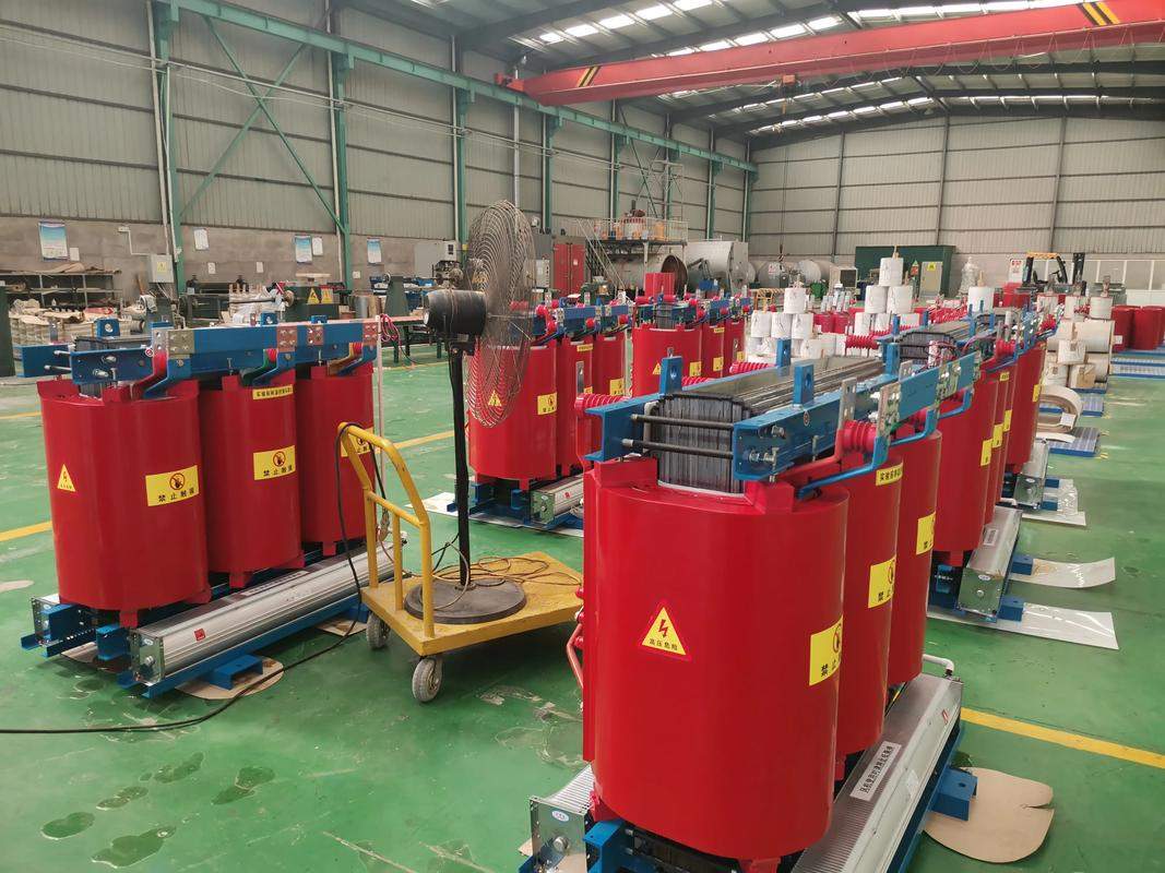
Temperature is the single most influential factor in determining the longevity of a dry-type transformer. Unlike oil-immersed units, dry-type transformers rely entirely on air cooling, making them more susceptible to environmental heat, restricted airflow, and internal hot spots. Since insulation deterioration is primarily a thermal-aging process, managing temperature is key to preserving transformer life.
Higher operating temperatures accelerate the chemical aging of insulation, which shortens the life of dry-type transformers. For every 10 °C increase in winding hot spot temperature, the insulation lifespan is cut by approximately 50%. Prolonged operation above the thermal limit of the insulation class (e.g., 130°C for Class B, 155°C for Class F, 180°C for Class H) can cause irreversible degradation and early failure.
Effective thermal control—through ventilation, load management, and real-time monitoring—significantly extends operational life.
Temperature has little effect on the service life of dry-type transformers.False
Temperature strongly influences insulation aging; exceeding thermal limits significantly reduces transformer service life.
The Thermal Aging Rule (Arrhenius Law in Practice)
| Hot Spot Temperature (°C) | Relative Insulation Life |
|---|---|
| 110 | 200% (extended life) |
| 120 | 150% |
| 130 | 100% (design life) |
| 140 | 50% |
| 150 | 25% |
| 160 | 12.5% |
A 10 °C rise = 50% reduction in expected insulation life (per IEC 60076-11 and IEEE C57.96)
Insulation Class vs. Maximum Hot Spot Temperature
| Insulation Class | Max Permissible Hot Spot Temp (°C) | Typical Life at Rated Temp |
|---|---|---|
| Class A | 105 | 15–20 years |
| Class B | 130 | 20–25 years |
| Class F | 155 | 25–30 years |
| Class H | 180 | 30–40 years |
Lifespan can be significantly extended by operating 10–20 °C below thermal limits.
Key Temperature Zones in Dry-Type Transformers
| Zone | Temperature Concern |
|---|---|
| Winding Hot Spot | Primary aging location for insulation |
| Core and Yoke Area | Affects magnetic losses and eddy heating |
| Air Exit Duct | Indicates cooling effectiveness |
| Terminal Lugs | Hot connections can cause localized loss |
| Tools for Monitoring | Thermal sensors, thermocouples, IR cameras, smart relays |
Common Causes of Excessive Temperature
| Cause | Impact on Transformer Life |
|---|---|
| Overloading | Increases copper losses (I²R) and hot spot temp |
| Blocked Airflow | Poor heat dissipation → insulation overheating |
| Dust Accumulation | Acts as thermal blanket, traps heat |
| Ambient Heat > 40 °C | Reduces cooling margin by 10–20 °C |
| Poor Room Ventilation | Causes cumulative daily temperature rise |
Temperature Rise vs. Aging Acceleration
| Condition | Approximate Lifespan Impact |
|---|---|
| Operated 10 °C below rating | Doubles expected life |
| Operated at rated temp | Full design life (~25–30 years) |
| Operated 10 °C above | Halves life (~12–15 years) |
| Frequent overload events | Adds thermal shock, cumulative aging |
Installations in hot climates or confined rooms must consider derating to compensate.
Best Practices to Minimize Thermal Stress
| Strategy | Benefit for Transformer Longevity |
|---|---|
| Use proper insulation class | Matches environmental and load expectations |
| Ensure open airflow path | Prevents hot spot formation |
| Install thermal sensors | Enables real-time load/temperature control |
| Conduct thermal imaging scans | Detects hidden overheating zones |
| De-rate in high-altitude or tropical conditions | Ensures core and winding do not exceed design limit |
Real-World Example – Temperature and Transformer Failure
- Application: Industrial dry-type transformer, 1600 kVA, Class F
- Normal loading: 80–95% continuous
- Issue: Ambient room temp reached 50 °C during summer
- Result: Hot spot exceeded 160 °C for 4+ hours/day
- Failure: Insulation breakdown and winding short in 9 years
- Corrective Action: Replaced with Class H transformer, added ventilation fans
Can Preventive Maintenance Extend the Service Life of Dry-Type Transformers?
Dry-type transformers are known for their safe, reliable, and low-maintenance operation. However, this does not mean they can be ignored. While oil-free designs eliminate many fluid-related concerns, exposure to heat, dust, moisture, and mechanical wear can still compromise performance and shorten service life. A structured preventive maintenance (PM) program is therefore essential—not only to avoid failure, but to maximize longevity and reduce operating costs.
Yes, preventive maintenance significantly extends the service life of dry-type transformers by keeping insulation systems intact, maintaining thermal performance, preventing contamination-related faults, and identifying emerging problems early. Routine tasks like cleaning, thermal scanning, insulation testing, and tightening terminals can prevent 80% of typical failures and ensure the transformer reliably operates for 30–40+ years.
Neglect leads to early degradation; preventive care ensures long-term reliability and cost savings.
Preventive maintenance is not necessary for dry-type transformers.False
Dry-type transformers require preventive maintenance to mitigate the effects of heat, dust, and aging on insulation and electrical performance.
Key Benefits of Preventive Maintenance
| Maintenance Focus | Life Extension Impact |
|---|---|
| Insulation integrity | Detects and prevents premature dielectric aging |
| Thermal control | Prevents overheating and hot spots |
| Mechanical tightness | Reduces vibration damage and arcing at connections |
| Dust and dirt removal | Maintains cooling airflow and reduces PD risk |
| Real-time monitoring | Enables predictive decisions and derating control |
Consistent preventive maintenance can extend service life by 10–15+ years.
Recommended Preventive Maintenance Activities
| Task | Frequency | Key Purpose |
|---|---|---|
| Visual inspection | Quarterly/Semi-annually | Check for cracks, discoloration, dust, and corrosion |
| Dust removal (vacuum/blow) | 6–12 months | Prevents thermal buildup and surface tracking |
| IR and PI insulation testing | Every 2–3 years | Detects insulation degradation and moisture ingress |
| Thermal imaging scan | Annually or seasonal | Identifies hot spots, loose terminals, and overload |
| Torque check of terminals | Annually | Prevents arcing, heating, and connection failure |
| Fan/ventilation verification | Annually | Ensures effective airflow and cooling |
| Load condition review | Annually | Confirms loading is within safe design limits |
Cost Comparison: Preventive vs. Reactive Maintenance
| Scenario | Preventive (Planned) | Corrective (Unplanned) |
|---|---|---|
| Annual Maintenance Cost | \$500–1,500/unit | — |
| Average Repair Cost (minor fault) | — | \$3,000–8,000 |
| Major Failure Replacement Cost | — | \$20,000–100,000+ |
| Downtime Risk | Low | High |
| Risk to Nearby Equipment | Minimal | Elevated due to fault propagation |
Studies show that 1 hour of planned maintenance saves 4+ hours of unplanned repair.
Real-World Case Study – Maintenance vs. Aging
| Parameter | Maintained Transformer | Unmaintained Transformer |
|---|---|---|
| Age | 28 years | 14 years |
| IR Value | >500 MΩ | <100 MΩ |
| Hot Spot Temperature | 115 °C | >145 °C |
| Insulation Condition | Clean, intact | Cracked, partial discharge |
| Service Status | Operational | Replaced due to failure |
Proper maintenance kept the maintained unit in reliable operation twice as long.
Tools and Techniques for Effective PM
| Tool/Method | Application Area |
|---|---|
| Infrared Camera | Detects thermal anomalies |
| Megger (IR Testing) | Measures insulation resistance |
| Polarization Index Meter | Evaluates moisture and insulation health |
| Vacuum and Air Compressor | Cleans coils and ducts |
| Vibration/Noise Analysis | Identifies mechanical looseness |
| Smart Monitoring Sensors | Tracks temperature and load trends |
Best Practices for PM Implementation
- Log every inspection and test result with timestamps and conditions.
- Establish a seasonal cleaning cycle, especially in dusty or humid environments.
- Use trend analysis on IR/PI values and thermal scans to detect deterioration.
- Create a critical asset register to prioritize transformers serving essential loads.
- Train personnel to recognize early visual and acoustic warning signs.
What Are Signs of Aging or Imminent Failure in Dry-Type Transformers?
While dry-type transformers are known for their safety and durability, they are not immune to degradation. Over time, insulation materials age, mechanical parts loosen, and contaminants accumulate—especially in dusty, hot, or poorly ventilated environments. Recognizing early signs of transformer aging or failure is crucial to prevent unplanned outages, equipment damage, or safety incidents.
Common signs of aging or imminent failure in dry-type transformers include visible cracks or discoloration on windings or insulation, elevated operating temperatures or hot spots, unusual noises or smells, declining insulation resistance (IR) values, and signs of contamination such as dust, moisture, or corrosion. Ignoring these warnings can lead to insulation breakdown, arcing, or catastrophic failure.
Early detection allows for repair, derating, or replacement before complete failure occurs.
Dry-type transformers do not display any signs before they fail.False
Most dry-type transformer failures are preceded by visible, measurable, or audible signs that indicate insulation or thermal deterioration.
1. Visual Signs of Insulation Aging
| Symptom | Meaning |
|---|---|
| Discoloration (brown/yellow) | Heat exposure or oxidized epoxy |
| Surface cracking or crazing | Mechanical aging, UV exposure, or vibration fatigue |
| Melting, dripping, or resin bubbling | Thermal overload or localized arcing |
| Dust accumulation | Blocks airflow, promotes corona discharge |
| Rust on clamps or terminals | Humidity or corrosive gas exposure |
Always conduct visual inspections with the transformer de-energized and fully cooled.
2. Electrical Testing Indicators
| Test Result | Interpretation |
|---|---|
| Insulation Resistance <100 MΩ | Possible insulation moisture or breakdown |
| Polarization Index <1.3 | Aging insulation or contamination |
| Unstable or trending IR decline | Progressive loss of dielectric strength |
| Unusual voltage drops at terminals | Loose connections or corroded joints |
| Recommended Tests | IR (Megger), PI, Capacitance, Power Factor (Tan δ) |
3. Thermal Performance Anomalies
| Sign | Possible Cause |
|---|---|
| Hot spot on thermal scan | Overload, loose connection, blocked airflow |
| Unusually warm terminals or busbars | Contact resistance or arcing |
| Excessive air exhaust temp | Internal overheating or loss of convection |
| Cooling fan activation under light load | Inadequate heat dissipation |
Compare thermal patterns to historical data for accurate trend analysis.
4. Acoustic and Olfactory Cues
| Cue | Interpretation |
|---|---|
| Humming changes or buzzing | Core loosening, vibration fatigue |
| Clicking or arcing sounds | Loose contacts or internal discharge |
| Burning smell or ozone odor | Insulation degradation or arcing near terminals |
| Intermittent noise with load changes | Tap changer wear (if equipped) |
These are early indicators of partial discharge, especially under high humidity.
5. Environmental Red Flags
| Condition | Long-Term Impact |
|---|---|
| Ambient temp > 40 °C | Accelerated insulation aging |
| High humidity or condensation | Moisture ingress into windings |
| Airborne dust (e.g., cement, wood fibers) | Dielectric surface contamination |
| Proximity to chemical vapors | Resin corrosion and accelerated breakdown |
| Protective Measures | Filters, dehumidifiers, isolation enclosures |
6. Mechanical Signs of Deterioration
| Observation | Failure Risk |
|---|---|
| Loose core clamps or brackets | Vibration damage, winding movement |
| Damaged terminal lug insulation | Increased corona or tracking |
| Sagging windings | Mechanical deformation from fault currents |
| Cracks at bushing entry | Aging, vibration, or thermal expansion |
Annual mechanical integrity checks are vital to prevent core and winding shift.
7. Load-Related Clues
| Load Behavior | Risk Implication |
|---|---|
| Frequent overloading (>110%) | Accelerated insulation thermal decay |
| Load cycling with wide amplitude | Mechanical and thermal stress |
| Unbalanced phases | Uneven heating, overload on single winding |
| Action Plan | Use real-time meters to log and correct load behavior |
Warning Signs Checklist
| Sign | Urgency to Act |
|---|---|
| Cracked or discolored insulation | HIGH |
| IR < 100 MΩ or PI < 1.3 | HIGH |
| Audible arcing or unusual noise | HIGH |
| Hot spots >150 °C on IR scan | HIGH |
| Dust layers or blocked vents | MEDIUM |
| Loose connections | MEDIUM–HIGH |
| Slight odor under load | MEDIUM |
Any combination of signs may signal imminent failure and demands immediate attention.
How to Maximize the Life of a Dry-Type Transformer?
Dry-type transformers are prized for their safety, reliability, and ease of installation—especially in indoor or restricted environments. While their design offers reduced fire risk and low maintenance, their lifespan is not unlimited. Environmental stress, thermal overload, contamination, and neglect can cause early aging. Fortunately, with proper care, a dry-type transformer can exceed 30–40 years of reliable service.
To maximize the life of a dry-type transformer, maintain optimal loading (typically 50–80% of rated capacity), ensure excellent ventilation, clean windings regularly, avoid moisture ingress, conduct preventive maintenance, perform insulation and thermal monitoring, balance the electrical load, and manage harmonics. Together, these practices protect insulation integrity, reduce thermal stress, and extend service life well beyond its design limit.
The key to transformer longevity is condition-focused operation, not just time-based expectations.
The service life of a dry-type transformer cannot be extended beyond its design life.False
With good operational practices and preventive maintenance, dry-type transformers can serve reliably for decades beyond their nominal design life.
1. Maintain Optimal Load Conditions
| Action | Lifespan Benefit |
|---|---|
| Operate at 50–80% of capacity | Keeps core and copper losses balanced |
| Avoid overloads (>100%) | Reduces thermal and mechanical stress |
| Monitor load cycles | Helps spot load peaks that accelerate aging |
| Balance 3-phase loads | Prevents hot spot formation and uneven wear |
| Tools | Smart meters, load loggers, SCADA integration |
2. Control Operating Temperature
| Factor | Method | Effect on Life Extension |
|---|---|---|
| Ambient room temperature | Install in climate-controlled or ventilated rooms | Reduces insulation hot spot stress |
| Winding hot spot temp | Use sensors or IR scans to detect high temp areas | Prevents premature aging of insulation |
| Thermal cycling | Avoid frequent cold-hot swings | Minimizes mechanical fatigue in windings |
| Fan-assisted ventilation | Use where ambient exceeds 40°C or in closed rooms | Helps maintain below-rated thermal conditions |
Each 10 °C reduction below rated temperature can double insulation lifespan.
3. Conduct Preventive Maintenance
| Maintenance Activity | Frequency | Life-Extending Impact |
|---|---|---|
| Visual inspection | Semi-annually | Detects cracks, discoloration, contamination |
| Dust removal (vacuum/air) | Every 6–12 months | Maintains airflow and prevents corona discharge |
| Insulation resistance (IR/PI) | Every 2–3 years | Detects aging insulation, moisture ingress |
| Thermal imaging | Annually or seasonally | Reveals thermal hotspots |
| Terminal torque checks | Annually | Prevents overheating and connection failure |
A structured PM plan can extend life by 10–15+ years and avoid early replacement.
4. Protect from Dust, Moisture, and Chemicals
| Risk Factor | Impact on Lifespan | Prevention Method |
|---|---|---|
| Airborne dust | Causes insulation tracking, restricts cooling | Routine cleaning, filters in ducts |
| Humidity/moisture | Leads to partial discharge and IR reduction | Install in dry rooms or use dehumidifiers |
| Corrosive gases or vapors | Damages insulation coating (epoxy/VPI) | Isolate from industrial emissions or HVAC vents |
| Install Location Best Practice | Clean, dry, vibration-free, temperature-regulated room |
5. Minimize Harmonic Distortion and Power Quality Issues
| Harmonic Source | Damage Mechanism |
|---|---|
| VFDs, UPSs, nonlinear loads | Induce additional core and winding losses |
| Unbalanced loading | Causes unequal phase heating |
| High Total Harmonic Distortion (THD) | Accelerates insulation deterioration |
| Mitigation Strategy | Use K-rated transformers, harmonic filters, or derating for harmonic-rich loads |
6. Choose Correct Insulation Class and Design for Environment
| Insulation Class | Max Temp (°C) | Application Suitability |
|---|---|---|
| Class B | 130 | Low-demand indoor applications |
| Class F | 155 | General-purpose industrial use |
| Class H | 180 | High-temp or heavy-duty use |
When exposed to warm environments or long cycles, consider Class H to increase thermal margin.
7. Implement Smart Monitoring and Data Logging
| System Feature | Longevity Benefit |
|---|---|
| Online temperature sensors | Tracks core and winding temps in real-time |
| Load profiling | Identifies overload or imbalance trends |
| Data trending software | Supports condition-based maintenance |
| Early warning alarms | Enables intervention before insulation is damaged |
Smart monitoring ensures transformers operate within life-preserving parameters 24/7.
8. When to Derate or Retire for Extended Operation
| Condition | Action for Life Maximization |
|---|---|
| High ambient temperature | Derate capacity by 5–10% |
| Old insulation but stable performance | Continue under reduced load |
| Minor insulation deterioration | Increase maintenance frequency, monitor IR closely |
| Structural aging (non-electrical) | Inspect clamps, brackets, and mounting |
Lifespan Summary by Operational Quality
| Operational Condition | Expected Service Life (Years) |
|---|---|
| Poor (dust, overloading, no PM) | 10–15 |
| Average (basic care, periodic checks) | 20–25 |
| Good (ventilation, clean, routine PM) | 25–30 |
| Excellent (all above + smart monitoring) | 35–40+ |
Conclusion
A well-designed, correctly installed, and properly maintained dry-type transformer can easily exceed its expected 25–30-year service life. Environmental conditions, thermal management, and routine upkeep are critical in extending its usable life. As with all electrical assets, proactive maintenance and early detection of stress or degradation ensure both operational reliability and long-term cost savings.
FAQ
Q1: What is the average life expectancy of a dry-type transformer?
A1: The typical life expectancy of a dry-type transformer is 20 to 30 years under normal operating conditions. With proper maintenance, environmental control, and load management, some units can exceed 35 years of reliable service.
Q2: What factors affect the lifespan of dry-type transformers?
A2: Several factors can influence how long a dry-type transformer lasts:
Ambient temperature and ventilation
Overloading or unbalanced loads
Moisture, dust, or corrosive environment
Cooling system performance (natural air or forced air)
Frequency and quality of maintenance inspections
Operating beyond design limits can significantly shorten transformer life.
Q3: How can you extend the life of a dry-type transformer?
A3: Life extension practices include:
Regular inspections for dust, cracks, or overheating
Vacuum cleaning and ventilation maintenance
Thermal imaging to detect hot spots
Load balancing to avoid overheating and stress
Ensuring proper ambient conditions, especially in enclosed or underground locations
Smart maintenance improves longevity and reliability.
Q4: How does dry-type transformer life compare to oil-immersed transformers?
A4: Oil-immersed transformers often last 25 to 40 years due to superior cooling and moisture protection.
Dry-type transformers, while lower maintenance and safer in fire-prone areas, may have shorter lifespans in harsh environments without proper care.
However, in controlled indoor settings, dry-type units can perform equally well or better.
Q5: When should a dry-type transformer be replaced?
A5: Consider replacement when:
Insulation resistance drops significantly
Cracks or deformation appear in windings or resin
Persistent hot spots are found during thermal scans
Excessive noise or vibration indicates internal wear
Unit fails to meet updated load or safety requirements
Timely replacement avoids costly failures and downtime.
References
"Dry-Type Transformer Lifespan and Maintenance" – https://www.electrical4u.com/dry-type-transformer-life
"IEEE C57.12.01: Standard for Dry-Type Distribution and Power Transformers" – https://ieeexplore.ieee.org/document/9065477
"Doble: Transformer Aging and Replacement Planning" – https://www.doble.com/transformer-aging-analysis
"NREL: Indoor Transformer Maintenance Practices" – https://www.nrel.gov/docs/fy22ost/dry-type-transformer-care.pdf
"ScienceDirect: Study on Aging of Cast Resin Transformers" – https://www.sciencedirect.com/dry-type-transformer-aging-study