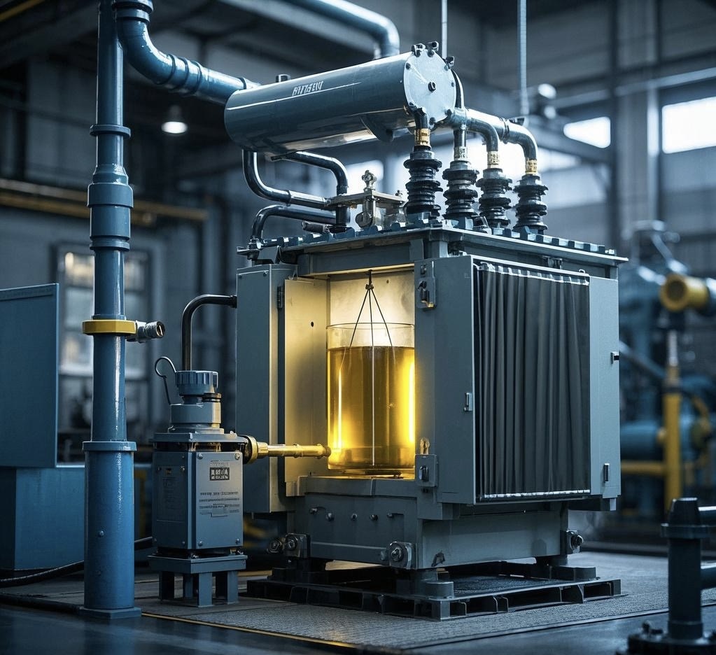
Oil-immersed transformers have served as the backbone of power systems for decades, prized for their reliability and thermal performance. However, with evolving grid demands, energy efficiency goals, and smart monitoring needs, many older units face obsolescence. Rather than replacing the entire unit, upgrading or modifying existing oil-immersed transformers offers a cost-effective path to enhanced performance, extended service life, and improved environmental compliance. This article explores the possibilities and key considerations of such upgrades.
What Performance Aspects Can Be Improved Through Transformer Upgrades?
In today’s energy sector, where grids face aging infrastructure, fluctuating demand, and rising sustainability pressures, transformer performance is no longer just a technical metric—it’s a financial, operational, and environmental imperative. Operating legacy transformers without upgrades can lead to increased energy losses, unscheduled outages, fire risk, and costly environmental non-compliance. Fortunately, targeted upgrades can significantly enhance transformer performance across multiple dimensions, often without full replacement. Understanding which aspects of performance can be improved—and how—is the key to futureproofing your grid assets and optimizing ROI.
Upgrades can improve transformer performance in key areas such as energy efficiency (loss reduction), thermal management, lifespan extension, fault diagnostics, insulation health, fire resistance, environmental compliance, and digital monitoring. These enhancements are achieved through core replacements, advanced insulation, smart sensor integration, eco-friendly fluid conversions, and AI-based health analytics. Performance improvements directly translate into lower lifecycle costs, enhanced reliability, regulatory compliance, and sustainability benefits.
Whether you’re a utility operator, facility manager, or EPC contractor, transformer upgrades offer a clear path to operational excellence. Let’s break down the performance aspects that matter most—and how to improve them.
Transformer upgrades can reduce no-load and load losses to improve energy efficiency.True
Upgrading core materials and winding designs can significantly reduce both types of energy losses, improving system-wide efficiency.
Replacing the entire transformer is always more economical than upgrading individual components.False
In many cases, targeted upgrades such as insulation replacement or sensor retrofits can extend equipment life at lower cost than full replacement.
Smart sensors and analytics platforms can significantly improve fault detection and reduce unplanned downtime.True
Digital upgrades enable real-time monitoring and predictive maintenance, which greatly reduces failure rates and extends transformer life.
Key Performance Areas That Benefit from Transformer Upgrades
1. Energy Efficiency (Loss Reduction)
Transformers experience two types of energy losses:
| Loss Type | Description | Upgrade Solutions |
|---|---|---|
| No-load Loss | Caused by magnetizing current when transformer is energized | Replace core with amorphous or low-loss silicon steel |
| Load Loss | Caused by resistance in windings during power flow | Upgrade winding conductor, improve cooling to reduce resistance |
Upgrading to amorphous core transformers can reduce no-load losses by up to 70%, and copper re-winding with optimized geometry can reduce load loss by 10–15%.
| Upgrade Path | Loss Reduction (%) | Payback Period |
|---|---|---|
| Core Replacement | 50–70 (no-load) | 3–5 years |
| Winding Upgrade | 10–15 (load) | 2–4 years |
These savings compound across large fleets and high-load environments.
2. Thermal Management and Cooling Performance
Heat buildup shortens transformer lifespan and increases failure risk.
| Limitation | Upgrade Path |
|---|---|
| Inefficient oil circulation | Install forced oil pumps or convert to ONAF or ODAF cooling |
| Air-cooled systems overheating | Add external fans or upgrade to advanced fins |
| High-load hotspots | Integrate thermal imaging sensors for hotspot detection |
Improved cooling can extend insulation life by 30–50%, directly impacting operational reliability.
3. Digital Monitoring and Smart Diagnostics
Older transformers lack predictive fault detection. Upgrading with smart sensors and analytics enables:
- Partial discharge detection
- Gas-in-oil analysis
- Vibration monitoring
- Load profile tracking
| Digital Tool | Function | Benefit |
|---|---|---|
| Bushing Monitors | Detect wear and internal arcing | Prevent catastrophic failure |
| DGA Sensors | Monitor dissolved gas anomalies | Early fault detection |
| Thermal Cameras | Track uneven heat distribution | Identify cooling failures |
These tools reduce unplanned outages by up to 60% and enable condition-based maintenance (CBM) strategies.
4. Insulation and Dielectric System Upgrades
Over time, insulation degrades due to thermal aging, oxidation, and moisture.
| Issue | Upgrade Solution |
|---|---|
| Cellulose paper aging | Replace with high-temperature aramid insulation |
| Moisture ingress | Install silica gel breathers or vacuum dry-out systems |
| Oxidized oil | Regenerate or replace with ester-based fluids |
Upgraded insulation systems can extend transformer life by 10–20 years and comply with modern fire and environmental standards.
5. Fire Safety and Environmental Risk Reduction
Fire-prone transformers pose safety and compliance hazards, especially in urban and indoor installations.
| Risk | Upgrade Option |
|---|---|
| Flammable oil | Convert to natural ester fluids (fire point >300°C) |
| PCB contamination | Flush and refill with PCB-free oil |
| No containment | Add spill bunds and flameproof enclosures |
Converting to biodegradable, high-flash-point fluids not only improves fire safety but also aligns with Stockholm Convention and REACH compliance.
6. Load Handling and Capacity Flexibility
Aging transformers often operate near or beyond their design capacity, leading to premature failures.
| Upgrade | Benefit |
|---|---|
| Load tap changer retrofit | Adjust voltage under load conditions |
| Cooling augmentation | Enable higher capacity without core upgrade |
| Parallel transformer integration | Share loads dynamically with smart switching |
These upgrades provide operational flexibility in rapidly growing load zones like data centers, renewables, and EV charging stations.
Real-World Case Studies of Performance Upgrades
| Utility | Upgrade | Result |
|---|---|---|
| EDF France | Core and winding upgrade in 110kV units | Reduced losses by 19%, ROI in 4 years |
| Dubai Electricity | Oil regeneration and smart sensors | Avoided 8 major failures over 2 years |
| National Grid UK | Ester oil conversion in urban substations | Achieved 100% compliance with fire codes |
These examples highlight proven performance gains and financial justification for upgrading.
Comparative Table: Upgrade Options and Performance Impact
| Upgrade Type | Performance Area Improved | Impact |
|---|---|---|
| Core Replacement | Energy efficiency | -70% no-load loss |
| Winding Optimization | Load loss and heating | -15% loss, cooler operation |
| Smart Sensors | Fault prediction | -60% unplanned outages |
| Insulation Upgrade | Dielectric strength | +20 years lifespan |
| Oil Change to Ester | Fire risk and eco-compliance | Fire point >300°C |
| Load Tap Changer | Voltage flexibility | Smoother grid balancing |
Can Transformer Components Be Retrofitted?
Transformers are designed for long-term service—often 30 years or more—but as grid demands grow and technology evolves, these aging assets can become performance bottlenecks or compliance liabilities. Fully replacing them, however, is often costly, disruptive, and unnecessary. The smarter approach? Retrofit the critical components. With proper planning and skilled execution, transformer retrofitting can extend equipment lifespan, reduce failure risk, improve monitoring, and meet new regulatory requirements—without full asset replacement. Whether you're in utility operations, heavy industry, or infrastructure, retrofitting gives your transformer fleet a new lease on life.
Yes, transformer components can be retrofitted to improve performance, reliability, monitoring, safety, and environmental compliance. Common retrofit components include bushings, load tap changers, cooling systems, insulation, sensors, control panels, and insulating fluids. These upgrades can be implemented in-situ and tailored to the transformer's design and service conditions. Retrofitting is often faster, less expensive, and less disruptive than full replacement, and is widely supported by OEMs and international standards like IEC 60076-19 and IEEE C57 series.
If you're managing aging transformers but aren’t ready for full replacement, retrofitting offers a scalable, strategic solution. Here's everything you need to know.
Transformer components such as bushings, sensors, and tap changers can be retrofitted.True
Many non-core components in transformers can be upgraded or replaced without removing the entire unit, extending its operational life.
Retrofitting transformer components violates OEM design standards and is not allowed.False
Retrofits are allowed and often supported by OEM guidelines, provided that components meet equivalent specifications and performance standards.
Transformer retrofits can include digital sensors and smart monitoring systems.True
Sensors for temperature, gas-in-oil analysis, and load monitoring are commonly retrofitted to enhance diagnostics and enable predictive maintenance.
What Transformer Components Can Be Retrofitted?
1. Bushings
Bushings are prone to insulation degradation, partial discharge, and oil leakage.
| Retrofit Option | Benefit |
|---|---|
| Replace with modern RIP (resin impregnated paper) or RIS (resin impregnated synthetic) bushings | Improved dielectric strength, no oil leaks |
| Add capacitive tap functionality | Enables advanced monitoring like tan delta testing |
| Install bushing monitoring system | Detect early internal failures |
Retrofitting bushings can prevent catastrophic failures and reduce dielectric stress across the transformer.
2. Load Tap Changers (LTCs)
LTCs manage voltage regulation under load and are mechanical wear points in many power transformers.
| Retrofit Type | Advantage |
|---|---|
| Mechanical replacement | Restores full tap operation; extends service by 10–15 years |
| Vacuum interrupter retrofit | Reduces arc erosion and maintenance |
| Digital LTC controllers | Enables fine voltage control and load balancing integration |
Modern LTC retrofits allow real-time SCADA control and reduce arc-related oil contamination.
3. Cooling Systems
Older transformers may lack efficient thermal regulation.
| Retrofit Component | Function |
|---|---|
| Forced air fans or oil pumps | Increase heat dissipation rate |
| Intelligent fan control | Adapts cooling to load dynamically |
| Heat exchangers | Reduce oil oxidation and moisture ingress |
Upgrading cooling improves load handling, thermal aging resistance, and oil longevity.
4. Monitoring and Sensor Systems
Digital retrofitting transforms a passive transformer into a smart, self-reporting device.
| Sensor Type | Installed Location | Monitored Parameter |
|---|---|---|
| DGA sensors | Oil tank or sampling port | Dissolved gases (fault gases) |
| Bushing monitors | Bushing tap | Capacitance, leakage current |
| Thermal sensors | Windings, tank, oil top | Hot spot detection |
| Vibration sensors | Tank and core mountings | Mechanical stress |
| Moisture-in-oil sensors | Oil chamber | Insulation health |
These components often integrate with cloud-based dashboards or utility SCADA systems, supporting predictive maintenance and fault isolation.
5. Control and Protection Relays
Legacy electromechanical relays can be upgraded with IEC 61850-compliant IEDs (Intelligent Electronic Devices).
| Retrofit Solution | Improvement |
|---|---|
| Digital protection relays | Faster, programmable fault response |
| SCADA-compatible control panels | Remote operation and logging |
| Arc-flash detection modules | Increases personnel safety |
This helps align older transformers with modern substation automation frameworks.
6. Insulating Fluid Retrofits
Replacing transformer oil can mitigate risks related to aging, contamination, and environmental hazards.
| Fluid Type | Retrofit Application |
|---|---|
| Natural ester oil | For fire-sensitive urban or indoor applications |
| Synthetic ester | High-temperature or moisture-prone environments |
| Mineral oil flush and replacement | For oxidized or contaminated systems |
Oil changeouts must include thorough flushing and vacuum drying, especially when switching from mineral to ester oils. This improves fire resistance and eliminates PCB legacy issues.
7. Insulation and Sealing System Upgrades
Over time, seals, gaskets, and cellulose insulation degrade.
| Component | Retrofit Material |
|---|---|
| Gaskets | Nitrile or silicon rubber (high resilience) |
| Tap changer seals | High-temp synthetic seals |
| Paper insulation | Replaced with aramid fiber (e.g., Nomex) |
Replacing these parts restores dielectric strength and improves oil containment.
Real-World Examples of Transformer Retrofitting
| Organization | Retrofit Scope | Result |
|---|---|---|
| Enel Italy | Retrofit of LTCs, bushings, and monitoring systems across 50 units | Extended service life by 12 years, improved voltage stability |
| Saudi Aramco | Ester oil conversion and SCADA upgrade in desert substations | Reduced fire risk, enabled remote diagnostics |
| Ontario Power Generation | Retrofitted IEDs and temperature sensors in nuclear plant transformers | Enhanced safety, reduced manual inspections |
Comparative Table: Retrofittable Transformer Components
| Component | Upgrade Type | Performance Gain |
|---|---|---|
| Bushings | RIP/RIS + sensors | Dielectric safety, condition monitoring |
| Load Tap Changer | Vacuum retrofit + digital control | Load adaptability, maintenance reduction |
| Cooling | Smart fans + pumps | 15–25% improved thermal performance |
| Sensors | DGA, moisture, vibration | Predictive maintenance, reduced faults |
| Relays | Digital IEDs | Faster protection, SCADA integration |
| Oil | Ester fluid | Fire safety, eco-compliance |
| Insulation/Seals | Aramid + new gaskets | Lifespan extension, leak prevention |
Regulatory and Technical Support for Retrofitting
Retrofitting is supported by:
- IEC 60076-19: Transformer risk assessment and life extension
- IEEE C57.143: Guide for LTC performance and evaluation
- ISO 14001: Environmental compliance in component replacement
- OEM retrofit kits and specifications for legacy units
Retrofits are often eligible for ESG reporting credit, especially those involving biodegradable oils or digital monitoring.
What Role Does Oil Treatment or Replacement Play in Transformer Upgrades?

Transformer oil is more than just a cooling and insulating medium—it is a critical component of a transformer's operational integrity. Over time, oil degrades due to thermal stress, moisture ingress, oxidation, and contamination. This degradation leads to reduced dielectric strength, accelerated insulation aging, and higher risk of failure. In transformer upgrades, treating or replacing oil can significantly improve performance, reliability, safety, and environmental compliance. Whether upgrading a legacy unit or extending the life of mid-cycle assets, oil management is one of the most cost-effective and impactful measures available.
Oil treatment or replacement plays a vital role in transformer upgrades by restoring dielectric strength, removing contaminants (moisture, acids, sludge, or PCBs), extending insulation life, improving thermal performance, and enabling eco-friendly or fire-safe operation. Regeneration, filtration, or fluid substitution supports performance goals while reducing environmental and safety risks. This process is often integrated with broader upgrades such as insulation retrofits, cooling enhancements, and digital monitoring installations.
Neglecting oil quality during an upgrade is like renovating a house without fixing the foundation. Here's how oil treatment fits into a high-impact upgrade strategy.
Transformer oil treatment restores dielectric strength and removes harmful contaminants like water and acids.True
Processes like vacuum dehydration, filtration, and regeneration remove impurities that degrade oil performance and transformer insulation.
Replacing mineral oil with biodegradable ester oil can improve fire safety and environmental compliance.True
Ester oils have higher fire points and are biodegradable, making them suitable for urban and sensitive installations under strict fire and eco regulations.
Oil treatment is only cosmetic and has no real effect on transformer performance.False
Oil quality directly impacts insulation integrity, thermal performance, and fault risk, making treatment critical for both safety and longevity.
Key Functions of Oil Treatment or Replacement in Transformer Upgrades
1. Restoring Dielectric Strength and Insulation Integrity
Aged oil accumulates water, acids, and particles that compromise dielectric performance.
| Oil Problem | Consequence | Treatment Method |
|---|---|---|
| High moisture | Low dielectric strength, insulation aging | Vacuum dehydration |
| Oxidized oil | Acid buildup, sludge formation | Fuller's Earth regeneration |
| Particle contamination | Partial discharges and hot spots | Fine filtration (1–5 micron) |
Target dielectric strength is typically >50 kV (ASTM D877). Treatment can restore degraded oil from <30 kV to ≥60 kV.
| Parameter | Before Treatment | After Treatment |
|---|---|---|
| Moisture Content (ppm) | 60–100 | <10 |
| TAN (Acidity) | >0.3 mg KOH/g | <0.05 |
| Dielectric Strength | <30 kV | ≥60 kV |
2. Extending Transformer Lifespan and Delaying Replacement
Oil treatment improves the condition of solid insulation (paper, pressboard), which determines transformer longevity.
- Dry oil slows cellulose aging rate.
- Sludge removal restores cooling channels.
- Clean oil reduces electrical stress and hotspot formation.
Combined with thermal management upgrades, oil treatment can extend transformer life by 10–15 years.
3. Supporting Other Upgrade Modules
| Upgrade Type | Oil's Role |
|---|---|
| Sensor integration | Requires clean, dry oil for accurate dissolved gas analysis (DGA) |
| LTC retrofits | Reduces arc byproducts and keeps new contacts clean |
| Cooling enhancements | Cleaner oil flows better, improving heat dissipation |
Oil condition directly affects the success of condition monitoring and fault prediction systems.
4. Switching to Eco-Friendly Insulating Fluids
Modern transformer retrofits often include replacing traditional mineral oil with:
| Fluid Type | Benefits | Applications |
|---|---|---|
| Natural Ester Oil | Biodegradable, high fire point (>300°C), moisture tolerant | Indoor, urban, eco-sensitive zones |
| Synthetic Ester | High oxidation stability, longer service life | Harsh environments, renewables |
| Silicone Fluids | Thermal stability, non-toxic | Hospitals, data centers, tunnels |
| Compliance Target | Fluid Solution |
|---|---|
| Fire safety (FM/UL) | Ester or silicone |
| Stockholm Convention (PCB-free) | Full flushing + ester fill |
| Carbon footprint | Low-VOC ester oils, recyclable packaging |
5. Eliminating PCB Contamination and Legacy Risk
Oil in old transformers may contain PCBs (polychlorinated biphenyls), a restricted substance under Stockholm and Basel Conventions.
| Action | Benefit |
|---|---|
| PCB testing (EPA 8082A or IEC 61619) | Confirms if oil is hazardous (>50 ppm) |
| Dechlorination treatment | Reduces PCB levels to non-hazardous classification |
| Complete oil replacement | Enables safe reclassification and disposal |
These processes are critical for legal compliance, environmental stewardship, and liability avoidance.
6. Improving Operational Safety and Fire Resistance
High-moisture, acidic, or contaminated oil increases:
- Risk of dielectric breakdown
- Internal arcing
- Flashover and fire events
Replacing mineral oil with ester fluids increases fire point from \~160°C to >300°C, making it suitable for:
- Schools and hospitals
- Underground substations
- High-density commercial zones
It also reduces spill cleanup costs due to biodegradability.
7. Supporting ESG and Sustainability Objectives
Utilities and industries upgrading transformers are under pressure to:
- Lower emissions
- Reduce hazardous waste
- Improve recyclability
Oil regeneration and biodegradable replacements help meet ISO 14001, REACH, and local EPR mandates.
| ESG Impact | Oil Upgrade Benefit |
|---|---|
| Scope 1 emissions | Fire-safe oils reduce combustion risk |
| Scope 3 emissions | Recycled/regenerated oil reduces supply chain emissions |
| Waste reduction | Regenerated oil reuse lowers hazardous waste disposal |
Real Case Applications of Oil Treatment in Upgrades
| Organization | Oil Upgrade | Outcome |
|---|---|---|
| EDF France | Regenerated oil in 220kV fleet | Avoided 7 asset replacements, saved €1.2M |
| State Grid China | Ester oil retrofit in eco zones | Achieved 100% fire safety compliance in 8 provinces |
| Abu Dhabi Water & Electricity | Oil analysis + drying before SCADA integration | Prevented 5 potential failures, improved DGA accuracy |
Summary Table: Oil Upgrade Methods and Their Functions
| Method | Function | When to Use |
|---|---|---|
| Filtration | Remove particles/sludge | Early aging, light contamination |
| Vacuum Dehydration | Remove moisture | High humidity zones, water ingress events |
| Fuller’s Earth Regeneration | Restore acid value, color, and resistivity | Aged oil with TAN >0.2 |
| Ester Oil Replacement | Fire safety, eco compliance | Urban/indoor or PCB legacy units |
| Dechlorination | PCB risk mitigation | Pre-1985 transformers, regulatory compliance |
Is It Possible to Add Digital Monitoring or IoT Sensors to Older Units?
In today’s energy sector, information is power—but many transformers still operate blind. Legacy transformers, despite being mechanically sound, lack the intelligence to communicate real-time health, stress, or failure risk. This data void leads to reactive maintenance, unplanned outages, and preventable breakdowns. The good news? Modern digital monitoring and IoT sensors can be seamlessly retrofitted to older transformers, turning passive assets into smart grid participants. It’s not only possible—it’s cost-effective, quick to deploy, and a major enabler of predictive maintenance, compliance, and long-term reliability.
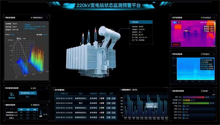
Yes, digital monitoring and IoT sensors can be added to older transformer units through retrofit kits and wireless or modular integration systems. These upgrades include temperature sensors, dissolved gas analyzers (DGAs), bushing monitors, load tracking modules, and gateway devices that transmit data to cloud or SCADA systems. Retrofit kits are designed to work independently of original manufacturer software, enabling legacy transformers to deliver real-time performance insights, fault detection, and predictive diagnostics without replacing the core unit.
This capability brings digital parity to aging infrastructure—let’s explore exactly how it's done and why it matters.
Legacy transformers can be retrofitted with digital monitoring systems.True
Modern sensor and gateway technologies allow utilities to add condition monitoring to existing transformers without full replacement.
Digital retrofitting requires removing or replacing the transformer’s core or windings.False
Most IoT retrofits are external and non-invasive, attaching to accessible surfaces, oil ports, or control cabinets.
IoT sensors can deliver predictive maintenance capabilities through data analytics.True
Sensors transmit key health metrics that enable predictive analytics platforms to detect early warning signs and recommend proactive maintenance.
What Types of Digital Monitoring Can Be Retrofitted?
1. Dissolved Gas Analysis (DGA) Monitors
These sensors track gas levels such as hydrogen, methane, and ethylene—early indicators of internal faults like arcing, overheating, and insulation degradation.
| Retrofit Type | Interface | Benefit |
|---|---|---|
| Inline DGA monitor | Installed on oil sampling port | Tracks fault gases continuously |
| Portable DGA kits | Handheld and WiFi-enabled | On-demand testing, ideal for fleet-wide screening |
These devices are typically non-invasive and plug-and-play, requiring no major modifications to tank or oil systems.
2. Temperature and Thermal Monitoring Sensors
Thermal stress is one of the most common causes of insulation failure. Retrofit options include:
- Winding temperature probes
- Top oil RTDs (Resistance Temperature Detectors)
- Infrared spot sensors
- External tank thermal strips
| Data Tracked | Use |
|---|---|
| Hot-spot temperature | Overload detection |
| Oil temperature trends | Cooling efficiency tracking |
| Tank skin heat | Early sign of blocked radiators or insulation degradation |
Paired with data loggers or edge IoT hubs, this thermal data can trigger alerts via SMS, SCADA, or cloud dashboards.
3. Bushing Monitoring Sensors
Bushings can fail catastrophically due to internal arcing or leakage. Retrofit sensors track:
- Leakage current
- Capacitance drift
- Tan delta (loss angle)
| Retrofit Method | Application |
|---|---|
| Clamp-on sensors | No internal modification needed |
| Capacitive taps | Used on newer bushings to extract diagnostic signals |
Advanced systems provide trend analysis and alarm thresholds, reducing the risk of unexpected failure.
4. Partial Discharge (PD) Detectors
PD activity inside or around insulation can precede major failure events.
| Sensor Type | Mounting |
|---|---|
| Acoustic or ultrasonic | Tank walls or bushings |
| UHF sensors | Cable terminations or GIS interfaces |
Modern PD kits include AI-based noise filtering and edge analytics for remote substations.
5. IoT Edge Gateways and Communication Modules
Sensors alone are not enough—data needs to be collected, processed, and transmitted.
| Component | Role |
|---|---|
| Edge gateway | Aggregates and preprocesses sensor data |
| Modbus or IEC 61850 modules | Connects to existing SCADA/EMS |
| Cloud connector | Sends encrypted data to cloud dashboards or mobile apps |
Gateways can communicate via 4G/5G, LoRaWAN, Wi-Fi, or Ethernet, depending on site conditions.
6. Smart Load and Voltage Monitoring
With the addition of non-invasive current and voltage sensors:
- Load profiles can be logged and analyzed
- Voltage imbalance and harmonics can be tracked
- Demand forecasting becomes possible using AI analytics
Useful in both urban substations and rural distribution transformers where manual checks are infeasible.
Real-World Examples of Digital Retrofits on Older Transformers
| Company | Retrofit Scope | Outcome |
|---|---|---|
| Hydro One (Canada) | 110 aging transformers fitted with DGA, oil moisture, and bushing monitors | Reduced unplanned failures by 46%, enabled condition-based maintenance |
| Eskom (South Africa) | Wireless thermal sensors and LTE gateways | Live fleet visibility for over 300 rural substations |
| Dubai DEWA | IoT kit added to oil-filled units in metro stations | Improved fault response times by 60%, improved ESG compliance reporting |
Summary Table: Retrofittable Digital Monitoring Technologies
| Technology | Sensor Type | Typical Mounting | Benefit |
|---|---|---|---|
| DGA Monitor | Gas sensor | Oil sampling valve | Fault gas detection |
| Thermal Sensor | RTD or IR | Winding or tank | Overheat prevention |
| Bushing Monitor | Current/capacitance sensor | Capacitive tap/clamp | Early warning on insulation breakdown |
| Partial Discharge | Acoustic/UHF | Surface or terminal | Insulation health |
| IoT Gateway | Edge processor | Panel-mounted | Data aggregation and transmission |
| Load Monitor | CTs and PTs | Clamp-on wiring | Energy usage profiling |
Advantages of Adding Digital Monitoring to Older Units
| Benefit | Description |
|---|---|
| Predictive Maintenance | Schedule service before failure occurs, based on real data |
| Extended Lifespan | Reduce stress, optimize load, and monitor insulation |
| Compliance & Reporting | Meet asset health mandates and ISO 55000 asset management standards |
| Asset Prioritization | Identify high-risk units for early upgrade or decommissioning |
| Low Cost, High Impact | Retrofit costs are often <15% of full transformer replacement |
Integration with Existing Systems
Digital retrofits can be linked to:
- SCADA systems (via Modbus, DNP3, IEC 61850)
- Mobile asset management apps
- Utility cloud platforms
- ESG and maintenance databases
Most kits come with open protocol compatibility, enabling fast deployment without IT overhauls.
How Do Load Requirements and System Changes Influence Upgrade Potential?
In today’s dynamic energy environment, transformer performance is no longer just a matter of legacy design—it must align with evolving load demands and system configurations. Many transformers were installed decades ago, sized for a static load profile. But now, with the rise of electric vehicles (EVs), distributed generation (like rooftop solar), battery storage, and variable industrial loads, the original capacity and configuration of transformers may no longer be optimal—or even safe. Understanding how load growth, variability, and system changes influence upgrade potential is critical to maximizing reliability, efficiency, and lifespan without unnecessary replacement costs.
Load requirements and system changes directly influence the upgrade potential of transformers by dictating thermal performance, voltage regulation capacity, dynamic load response, and fault tolerance. As load increases, fluctuates, or shifts geographically, transformers may require upgrades in windings, cooling systems, tap changers, and monitoring technologies to handle new operational stress. System-level changes—such as renewable integration, demand-side management, or grid automation—also demand upgrades to insulation, relay protection, and communication interfaces to maintain performance and regulatory compliance.
Ignoring the influence of evolving system demands can result in overload, accelerated aging, increased losses, and premature failure. Upgrades tailored to real-world system dynamics protect both performance and investment.
Transformer upgrades can be tailored to meet increased or more variable load demands.True
Retrofits and enhancements can improve thermal handling, cooling, and voltage regulation to accommodate changing load profiles.
Transformers must be replaced entirely if there are changes in system topology or load growth.False
Upgrades can be targeted to extend capacity, improve flexibility, and adapt to new system demands without full replacement.
Adding distributed generation and storage to the grid influences transformer load behavior and requires reassessment of performance.True
Decentralized energy sources affect loading patterns and can introduce harmonics or voltage swings that transformers must be upgraded to manage.
Understanding the Relationship Between Load Growth and Transformer Upgrade Needs
1. Thermal Stress and Overload Conditions
As the system load increases or fluctuates, transformers face higher heat generation and shorter cool-down cycles.
| Load Change | Transformer Impact | Upgrade Strategy |
|---|---|---|
| Peak demand rise (EV stations, industry) | Overheating, insulation stress | Upgrade cooling system, optimize winding geometry |
| Increased duty cycle | Reduced off-time for thermal recovery | Add forced oil/air cooling (ODAF/ONAF) |
| Load imbalance | Hotspots, winding degradation | Rewind with better current distribution |
For transformers operating near their original nameplate capacity, thermal upgrades can improve capacity by 10–30% without exceeding insulation ratings.
2. Dynamic and Variable Loads (e.g., EVs, Renewables, BESS)
Modern grid elements bring load unpredictability:
- EV charging introduces high-frequency, short-duration peak loads
- Rooftop solar and wind cause load reversals and voltage swings
- Battery storage cycles rapidly between charge/discharge
| Challenge | Required Upgrade |
|---|---|
| Rapid current fluctuation | Add surge-resistant windings and faster-responding relays |
| Load reversal (export mode) | Upgrade voltage regulation systems |
| Harmonic distortion | Install harmonic filters or shielded windings |
Adding sensors and analytics helps monitor load variability and trigger load-based tap control in real time.
3. System Topology Changes (Grid Expansion or Reconfiguration)
Changes like feeder re-routing, substation re-zoning, or distributed energy integration alter transformer load profiles.
| System Change | Transformer Response | |
|---|---|---|
| Feeder consolidation | Increased throughput required | Upgrade bushing current rating and core capacity |
| Loop to radial topology | Reduced redundancy | Install fast fault isolation and SCADA integration |
| Rural to urban conversion | Load type shift (motor loads to EVs, HVAC) | Adjust cooling and load tracking sensitivity |
Digital relays and intelligent monitoring systems provide essential adaptability for altered fault response patterns.
4. Voltage Fluctuations and Regulation Requirements
Growing load density or DER integration may create voltage instability, requiring better control.
| Voltage Issue | Retrofit Solution |
|---|---|
| Drop under heavy load | Retrofit On-Load Tap Changer (OLTC) |
| Voltage rise from solar export | Add reverse-power protection and adaptive voltage control |
| Oscillations at peak times | Add damping logic and automated relays |
Voltage regulation upgrades protect both downstream devices and customer satisfaction.
Real-World Examples of Load-Responsive Transformer Upgrades
| Project | Load/System Shift | Upgrade Performed | Outcome |
|---|---|---|---|
| California Utility | Rapid EV infrastructure rollout | Cooling fans, SCADA tap changers | 20% capacity buffer achieved |
| German DSO | Rooftop solar surge in rural grids | Installed bushing sensors and voltage control IEDs | Prevented voltage rise events |
| Middle East Industrial Park | Load changed from mixed to high-motor use | Rewound transformers and upgraded protection relays | Eliminated 3 overload trips/month |
These show that careful load analysis leads to precise, efficient upgrades.
Analytical Tools Used to Assess Upgrade Potential
| Tool | Function |
|---|---|
| Load forecasting software | Projects 5–10 year demand trends |
| Thermal modeling (FEA) | Simulates hotspot risk under load |
| Load flow analysis (SCADA or EMS) | Identifies voltage sags, losses, overload nodes |
| Harmonic analysis | Detects waveform distortion risks |
| Transformer loading profile audits | Compares actual vs. rated utilization |
These inputs allow asset managers to prioritize upgrades by urgency and return on investment.
Upgrade Options Based on Load/System Profiles
| Condition | Upgrade Option | Performance Gain |
|---|---|---|
| Peak load increase | Enhanced cooling (ODAF, fans) | +20–30% capacity margin |
| Variable solar input | Tap changer with adaptive logic | Stable voltage under load reversal |
| Night-time EV surges | Smart relay with time-based curve | Balanced grid response |
| Load shift to motors | Rewinding for better impedance control | Lower heating, better power factor |
| Grid reconfiguration | Digital IEDs and gateway upgrades | Faster protection and dynamic control |
Compliance and Futureproofing Considerations
Grid regulators often now mandate:
- Load-aware transformer design reviews
- Proof of harmonics and reverse flow mitigation
- Dynamic loading capabilities for grant or ESG funding
Retrofitting legacy units to meet these requirements is often faster and cheaper than re-engineering grid infrastructure.
What Are the Risks or Limitations of Transformer Modification?
While transformer modification offers a powerful route to enhanced performance, cost savings, and asset extension, it is not without challenges. Transforming an older or custom-built unit through modification demands deep technical insight, strict adherence to design tolerances, and careful evaluation of side effects. Without a thorough engineering assessment, modifications can inadvertently introduce thermal imbalances, dielectric failures, regulation instability, or non-compliance with safety codes. Understanding the risks and limitations involved in transformer modification is crucial to ensuring that upgrades are both effective and safe.
Transformer modifications carry technical and regulatory risks such as thermal stress misalignment, insulation incompatibility, mechanical vibration, altered magnetic flux paths, relay coordination issues, and potential warranty or compliance violations. These limitations arise due to the interdependent nature of core, winding, cooling, and control systems. Modifications must be guided by detailed simulation, OEM design matching, and IEC/IEEE standard compliance to prevent performance degradation or failure.
Modifications can be transformative—but without caution and expertise, they can also be catastrophic. Below is a technical breakdown of what to watch for.
Transformer modifications can introduce risks if design parameters are not properly matched.True
Modifications that ignore original design tolerances, thermal limits, or dielectric coordination can lead to instability or failure.
Modifying a transformer always voids compliance with standards like IEC 60076 or IEEE C57.False
Modifications are allowed and often guided by IEC/IEEE frameworks, provided that post-modification testing and documentation are validated.
Transformer modification may impact warranty and require coordination with the OEM.True
OEMs often require pre-approval or certified engineering review for modifications to maintain warranty and liability coverage.
Major Risks and Limitations in Transformer Modification
1. Thermal Mismatch and Hotspot Risk
Transformers are thermally calibrated systems. Changing windings, cooling systems, or insulation without full recalibration may cause:
| Risk | Cause | Result |
|---|---|---|
| Uneven hotspot formation | New winding design or oil flow disturbance | Accelerated aging, insulation failure |
| Inadequate cooling | Increased losses or different heat paths | Shortened transformer life |
Any modification should be preceded by thermal simulation (e.g., FEA models) to predict temperature behavior.
2. Dielectric Breakdown and Insulation Incompatibility
Upgrading oil, bushings, or internal barriers can cause mismatched dielectric clearances or impulse withstand voltages (BIL).
| Issue | Root Cause | Effect |
|---|---|---|
| Overstressed insulation | Modified core or re-rated voltage | Internal arcing |
| Incompatible insulation materials | New fluids or seals added | Degraded dielectric strength or chemical incompatibility |
Always perform dielectric coordination studies and compatibility checks, especially when switching to ester fluids or new winding configurations.
3. Mechanical and Vibration Instability
Adding or replacing internal parts (e.g., windings, cores, or tap changers) may disrupt mechanical balance.
| Modification | Mechanical Risk |
|---|---|
| Core tightening | Increases resonance if not aligned with vibration damping |
| Winding change | Affects magnetic forces and tank stress |
| Fan additions | Causes tank flexure if not properly supported |
Unaddressed vibration leads to loose parts, insulation chafing, and fatigue fractures.
4. Flux Distribution and Magnetic Circuit Distortion
Changes to the magnetic core or coil geometry may misalign flux paths, creating:
- Stray flux leakage
- Increased no-load losses
- Overheating near core clamps or tank walls
Proper magnetic simulation and flux containment review are essential during structural modifications.
5. Protection Scheme Disruption
Replacing LTCs, adding sensors, or upgrading controls can alter fault current profiles and relay timing.
| Impact | Result |
|---|---|
| Faster fault current rise | Existing relays may misoperate |
| Increased trip burden | Incompatibility with feeder protection settings |
| Fault detection delay | Risk of transformer tank rupture or bus damage |
Always conduct a relay coordination study post-modification, especially for grid-tied transformers.
6. Non-Compliance with OEM and International Standards
Modifications must align with:
- IEC 60076 series (design, thermal, dielectric)
- IEEE C57.12 & C57.143 (performance and tap changer guidelines)
- ISO 14001 / 45001 (environmental and safety)
Failure to comply risks:
- Insurance invalidation
- Warranty voiding
- Inspection or audit failure
Post-modification testing must include:
- Impulse testing
- Dielectric withstand
- Load/no-load loss re-verification
- Thermal rise testing
7. Documentation Gaps and Nameplate Inaccuracy
Modifications may make the original nameplate obsolete or misleading, leading to errors in:
- System load planning
- Compliance audits
- Future maintenance
| Required Documentation Update | Includes |
|---|---|
| New test reports | Type and routine tests |
| Modified nameplate | New power rating, insulation level |
| Maintenance procedures | Updated intervals and component specs |
Always issue a revision-controlled modification record per ISO 9001 asset tracking.
Summary Table: Risks vs. Mitigation Strategies
| Risk Area | Specific Concern | Mitigation Method |
|---|---|---|
| Thermal Overload | New windings create hotspots | FEA-based thermal simulations |
| Dielectric Failure | Incompatible insulation materials | Coordination studies, oil compatibility tests |
| Mechanical Instability | Vibration or stress misalignment | Structural dampening design |
| Magnetic Imbalance | Stray flux overheating | Magnetic field modeling |
| Relay Misoperation | Changed fault response curves | Protection system re-tuning |
| Compliance Gaps | Standard violation or documentation lapse | Post-mod test & documentation package |
| OEM Warranty | Voided due to unauthorized changes | OEM consultation and certified retrofitter involvement |
Real-World Incidents of Improper Transformer Modification
| Case | What Went Wrong | Result |
|---|---|---|
| Substation in Brazil | Winding upgraded without cooling match | Internal tank fire, total loss |
| Oil field transformer in Texas | Changed to ester oil without gasket compatibility check | Leaked fluid, environmental fine |
| Utility in Europe | Added tap changer with incorrect relay delay | Relay failed to trip during LTC arc event |
Each failure illustrates the cost of unvalidated modifications—both financially and operationally.
Conclusion
Yes—oil-immersed transformers can be upgraded and modified to significantly enhance performance, especially when full replacement is not feasible. From component retrofits to smart monitoring and oil rejuvenation, these improvements can extend operational life, improve energy efficiency, and adapt to modern grid requirements. However, a careful technical assessment is essential to ensure modifications are compatible with the transformer’s design and long-term reliability goals.
FAQ
Q1: Can oil-immersed transformers be upgraded or modified?
A1: Yes, oil-immersed transformers can be upgraded to extend service life and improve performance. Upgrades may include:
Improved cooling systems (e.g., fans, radiators, pumps)
Advanced monitoring and protection relays
Better insulating materials and bushings
Oil filtration or replacement with natural esters
Such retrofits help meet modern efficiency and reliability standards.
Q2: What performance improvements can be achieved through upgrades?
A2: Upgrading can deliver:
Increased energy efficiency (reduced core and copper losses)
Enhanced cooling and thermal stability
Extended operational lifespan
Improved safety and environmental compliance
Real-time monitoring and fault diagnostics
These enhancements reduce the risk of unplanned outages and lower O&M costs.
Q3: What components of an oil-immersed transformer are typically upgraded?
A3: Key components suitable for upgrade include:
Cooling systems: Add or replace fans, radiators, or pumps
Bushing assemblies: Replace with higher-rated or better-insulated units
Insulating oil: Switch to biodegradable or high-performance oils
Tap changers: Upgrade to automatic or vacuum-type models
Protection relays: Replace electromechanical types with digital relays
Each upgrade enhances efficiency, safety, or load-handling capabilities.
Q4: Is oil treatment an effective upgrade?
A4: Absolutely. Oil treatment is a critical upgrade that involves:
Vacuum dehydration and degassing
Filtration to remove moisture, sludge, and acids
Replacement with natural ester oils for improved fire safety and biodegradability
This restores dielectric strength, protects insulation, and supports long-term reliability.
Q5: What are the challenges or limitations of upgrading oil-immersed transformers?
A5: Challenges may include:
Cost-benefit analysis: Upgrading may be less economical than replacement for very old units
Downtime: Some upgrades require taking the unit offline
Compatibility issues: Not all modern components fit older designs
Regulatory approvals: For oil type changes or capacity enhancements
Despite these, most upgrades are cost-effective compared to new equipment and can delay capital expenditures.
References
"Upgrading Oil-Immersed Transformers" – https://www.electrical4u.com/transformer-upgrades
"IEEE C57.140: Evaluation of Liquid-Immersed Transformers for Refurbishment" – https://ieeexplore.ieee.org/document/8965624
"Doble: Performance Improvements for Aged Transformers" – https://www.doble.com/transformer-performance-upgrades
"ScienceDirect: Case Studies on Transformer Retrofit and Re-Engineering" – https://www.sciencedirect.com/transformer-upgrade-retrofit