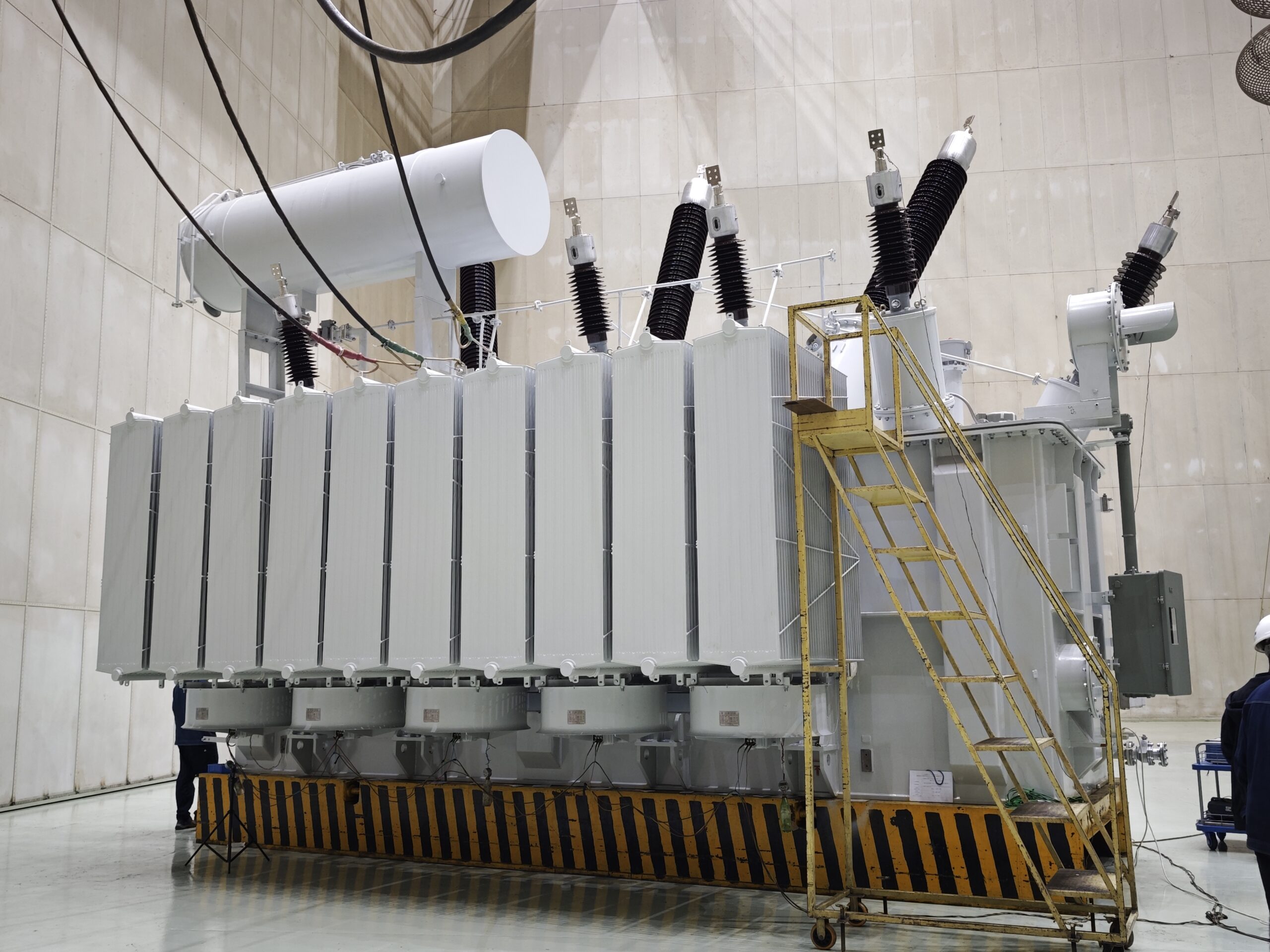
Transformers are vital assets in power systems, often operating for decades under demanding conditions. However, age, environmental stress, load changes, and evolving performance standards eventually lead to reduced efficiency or failure. When issues arise, asset managers must choose between repairing, retrofitting, or replacing the transformer. Making the right decision at the right time can optimize operational reliability, cost-efficiency, and safety. This article outlines how to evaluate these options based on condition, performance, and strategic goals.
What Are the Risks or Limitations of Transformer Modification?
While transformer modification offers a powerful route to enhanced performance, cost savings, and asset extension, it is not without challenges. Transforming an older or custom-built unit through modification demands deep technical insight, strict adherence to design tolerances, and careful evaluation of side effects. Without a thorough engineering assessment, modifications can inadvertently introduce thermal imbalances, dielectric failures, regulation instability, or non-compliance with safety codes. Understanding the risks and limitations involved in transformer modification is crucial to ensuring that upgrades are both effective and safe.
Transformer modifications carry technical and regulatory risks such as thermal stress misalignment, insulation incompatibility, mechanical vibration, altered magnetic flux paths, relay coordination issues, and potential warranty or compliance violations. These limitations arise due to the interdependent nature of core, winding, cooling, and control systems. Modifications must be guided by detailed simulation, OEM design matching, and IEC/IEEE standard compliance to prevent performance degradation or failure.
Modifications can be transformative—but without caution and expertise, they can also be catastrophic. Below is a technical breakdown of what to watch for.
Transformer modifications can introduce risks if design parameters are not properly matched.True
Modifications that ignore original design tolerances, thermal limits, or dielectric coordination can lead to instability or failure.
Modifying a transformer always voids compliance with standards like IEC 60076 or IEEE C57.False
Modifications are allowed and often guided by IEC/IEEE frameworks, provided that post-modification testing and documentation are validated.
Transformer modification may impact warranty and require coordination with the OEM.True
OEMs often require pre-approval or certified engineering review for modifications to maintain warranty and liability coverage.
Major Risks and Limitations in Transformer Modification
1. Thermal Mismatch and Hotspot Risk
Transformers are thermally calibrated systems. Changing windings, cooling systems, or insulation without full recalibration may cause:
| Risk | Cause | Result |
|---|---|---|
| Uneven hotspot formation | New winding design or oil flow disturbance | Accelerated aging, insulation failure |
| Inadequate cooling | Increased losses or different heat paths | Shortened transformer life |
Any modification should be preceded by thermal simulation (e.g., FEA models) to predict temperature behavior.
2. Dielectric Breakdown and Insulation Incompatibility
Upgrading oil, bushings, or internal barriers can cause mismatched dielectric clearances or impulse withstand voltages (BIL).
| Issue | Root Cause | Effect |
|---|---|---|
| Overstressed insulation | Modified core or re-rated voltage | Internal arcing |
| Incompatible insulation materials | New fluids or seals added | Degraded dielectric strength or chemical incompatibility |
Always perform dielectric coordination studies and compatibility checks, especially when switching to ester fluids or new winding configurations.
3. Mechanical and Vibration Instability
Adding or replacing internal parts (e.g., windings, cores, or tap changers) may disrupt mechanical balance.
| Modification | Mechanical Risk |
|---|---|
| Core tightening | Increases resonance if not aligned with vibration damping |
| Winding change | Affects magnetic forces and tank stress |
| Fan additions | Causes tank flexure if not properly supported |
Unaddressed vibration leads to loose parts, insulation chafing, and fatigue fractures.
4. Flux Distribution and Magnetic Circuit Distortion
Changes to the magnetic core or coil geometry may misalign flux paths, creating:
- Stray flux leakage
- Increased no-load losses
- Overheating near core clamps or tank walls
Proper magnetic simulation and flux containment review are essential during structural modifications.
5. Protection Scheme Disruption
Replacing LTCs, adding sensors, or upgrading controls can alter fault current profiles and relay timing.
| Impact | Result |
|---|---|
| Faster fault current rise | Existing relays may misoperate |
| Increased trip burden | Incompatibility with feeder protection settings |
| Fault detection delay | Risk of transformer tank rupture or bus damage |
Always conduct a relay coordination study post-modification, especially for grid-tied transformers.
6. Non-Compliance with OEM and International Standards
Modifications must align with:
- IEC 60076 series (design, thermal, dielectric)
- IEEE C57.12 & C57.143 (performance and tap changer guidelines)
- ISO 14001 / 45001 (environmental and safety)
Failure to comply risks:
- Insurance invalidation
- Warranty voiding
- Inspection or audit failure
Post-modification testing must include:
- Impulse testing
- Dielectric withstand
- Load/no-load loss re-verification
- Thermal rise testing
7. Documentation Gaps and Nameplate Inaccuracy
Modifications may make the original nameplate obsolete or misleading, leading to errors in:
- System load planning
- Compliance audits
- Future maintenance
| Required Documentation Update | Includes |
|---|---|
| New test reports | Type and routine tests |
| Modified nameplate | New power rating, insulation level |
| Maintenance procedures | Updated intervals and component specs |
Always issue a revision-controlled modification record per ISO 9001 asset tracking.
Summary Table: Risks vs. Mitigation Strategies
| Risk Area | Specific Concern | Mitigation Method |
|---|---|---|
| Thermal Overload | New windings create hotspots | FEA-based thermal simulations |
| Dielectric Failure | Incompatible insulation materials | Coordination studies, oil compatibility tests |
| Mechanical Instability | Vibration or stress misalignment | Structural dampening design |
| Magnetic Imbalance | Stray flux overheating | Magnetic field modeling |
| Relay Misoperation | Changed fault response curves | Protection system re-tuning |
| Compliance Gaps | Standard violation or documentation lapse | Post-mod test & documentation package |
| OEM Warranty | Voided due to unauthorized changes | OEM consultation and certified retrofitter involvement |
Real-World Incidents of Improper Transformer Modification
| Case | What Went Wrong | Result |
|---|---|---|
| Substation in Brazil | Winding upgraded without cooling match | Internal tank fire, total loss |
| Oil field transformer in Texas | Changed to ester oil without gasket compatibility check | Leaked fluid, environmental fine |
| Utility in Europe | Added tap changer with incorrect relay delay | Relay failed to trip during LTC arc event |
Each failure illustrates the cost of unvalidated modifications—both financially and operationally.
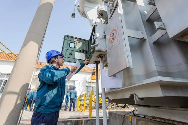
When Is Repair the Most Practical Option?
Not every transformer issue demands replacement or an expensive retrofit. In many cases, targeted repair is the most practical, efficient, and financially responsible option, especially when faults are isolated, the unit’s core design remains sound, and the failure hasn’t caused systemic degradation. However, determining when repair is appropriate versus when upgrade or replacement is required demands more than guesswork—it requires technical diagnostics, risk assessment, and lifecycle cost analysis. For fleet operators, EPCs, or utility asset managers, making the right call can save millions while preserving reliability.
Repair is the most practical option when the transformer’s core (magnetic circuit), tank structure, and insulation system remain fundamentally intact, and failures are limited to components such as bushings, gaskets, tap changers, or auxiliary systems. Repairs are especially suitable for units with moderate service age, minor oil leaks, mechanical wear, or replaceable part degradation. A repair-first approach is justified when diagnostics confirm localized faults, cost of repair is significantly lower than retrofitting or replacing, and asset criticality allows for short downtime during restoration.
Repairs, when correctly applied, maximize return on investment and prevent premature asset retirement. Here’s how to determine when they’re the smartest choice.
Transformer repair is most practical when failures are localized and the core structure is intact.True
Localized failures in bushings, gaskets, or OLTCs can be repaired without impacting the transformer’s magnetic integrity or insulation life.
Even minor transformer damage requires a full replacement to restore performance.False
Many transformers with moderate wear or single-component faults can be safely and effectively repaired without full replacement.
Oil leaks, failed bushings, or tap changer issues are common repair scenarios for aged transformers.True
These faults are isolated, component-level failures and are often economically repairable.
Conditions That Make Repair the Most Practical Solution
1. Component-Level Failure with Healthy Core and Windings
| Fault Type | Repairable Components |
|---|---|
| Cracked or leaky bushings | Replace with compatible RIP/RIS or porcelain bushings |
| Tap changer malfunction | OLTC diverter or selector switch replacement |
| Worn or leaking gaskets | Seal kits, flange inspection, and re-tightening |
| Minor oil contamination | Filter and degasification or top-off |
| CT/VT failure | Auxiliary component swap |
If insulation resistance, DGA, and capacitance tests confirm good internal condition, a full overhaul is unnecessary.
2. Moderate Service Age and Favorable Oil Test Results
Repairs are most economical when the unit has:
- 15–25 years of service (midlife)
- TAN (acid number) < 0.2 mg KOH/g
- Moisture < 30 ppm
- DGA shows no critical fault gases
| Diagnostic Test | Good for Repair? | Threshold |
|---|---|---|
| Insulation Resistance | Yes | >1 GΩ |
| Furan Analysis | Yes if <500 ppb | Indicates paper insulation health |
| Partial Discharge | No if active | May require deeper intervention |
Aged but healthy units may simply need part-level attention, not major intervention.
3. Short Turnaround Requirements
Transformer replacement can take 6–12 months. Repair:
- Typically takes 2–6 weeks
- Requires fewer regulatory permits
- Can often be done on-site or in regional repair hubs
When critical assets must return to service rapidly (e.g., hospitals, substations, data centers), repair offers minimal operational disruption.
4. Clear Financial Justification
| Option | Typical Cost (% of Replacement) | Considerations |
|---|---|---|
| Repair | 10–30% | High ROI if core and insulation are sound |
| Upgrade | 40–70% | Includes component + system improvements |
| Replacement | 100% | Highest cost, longest lead time |
For budget-constrained utilities or short CAPEX cycles, repair may be the only practical short-term strategy.
5. Non-Critical Faults with Low Safety Risk
Repairs are ideal when issues don’t compromise dielectric integrity or thermal performance, such as:
- Minor leaks
- Fan or control system failure
- Low-impact corrosion
- Cabinet or enclosure damage
A risk-based approach allows operators to prioritize serious faults for upgrade, while repairing less critical issues to keep the unit operational.
Common Repairable Fault Scenarios and Actions
| Fault | Repair Action |
|---|---|
| Oil Leak at Flange | Remove gasket, reseal, torque to spec |
| Noisy Tap Changer | Inspect diverter, replace contacts, reset timing |
| Gas Accumulation (Low Risk) | Oil degassing + filtration |
| Low Dielectric Strength | Top-off with high-grade oil, vacuum fill |
| Cracked Bushing | Replace with IEC-rated equivalent |
| Radiator Failure | Replace or clean fins, test oil flow |
Mobile repair teams can conduct many of these without crane lifts or removal from pad.
When Repair Is Not Advisable
| Condition | Better Solution |
|---|---|
| Damaged windings or insulation collapse | Replacement or full rewind |
| High PD activity or furan >1000 ppb | Overhaul or decommission |
| PCB contamination >50 ppm | Dechlorination or disposal |
| Multiple prior repairs with declining test scores | Replacement recommended |
| Load capacity mismatch with new system design | Upgrade or redesign |
Repair must always be based on current test data and lifecycle performance forecasting.
Summary Table: Repair Suitability Matrix
| Factor | Repairable? | Red Flag? |
|---|---|---|
| Bushings cracked | ✅ Yes | ❌ Only if internal arcing present |
| Core overheating | ❌ No | 🔴 Needs full analysis or replacement |
| Oil acidity <0.2 TAN | ✅ Yes | 🔶 Continue monitoring |
| Winding displacement | ❌ No | 🔴 Structural rebuild required |
| Moisture <30 ppm | ✅ Yes | 🟢 Treat with dehydration |
| Tap changer misaligned | ✅ Yes | 🟢 Replace contacts or realign |
| Internal arcing | ❌ No | 🔴 Upgrade or disposal likely |
Real-World Cases Where Repair Was the Best Option
| Company | Scenario | Repair Action | Savings vs Replacement |
|---|---|---|---|
| Midwest Utility (US) | 138kV bushing cracked | OEM bushing retrofit on-site | Saved \$450,000 |
| Oil Refinery (UAE) | Leaking radiator fins | Cleaned, pressure tested, resealed | 85% cost reduction |
| State Grid (China) | OLTC noise and oil degradation | Tap overhaul + oil top-off | Avoided 7-month downtime |
In each case, repair extended service life by 5–10 years and improved cost-efficiency.
What Is Retrofitting, and When Is It Beneficial?
Transformers are built to last decades—but the grid is not. Load demands grow, regulations tighten, digital expectations rise, and system designs shift. Many older transformers, though structurally sound, fall short in terms of performance, monitoring, or environmental compliance. Yet replacing them can be costly, time-consuming, and logistically disruptive. That’s where retrofitting comes in: a cost-effective solution that injects new life into existing infrastructure. Done properly, transformer retrofitting enhances reliability, safety, intelligence, and sustainability—without the cost or lead time of full replacement.
Retrofitting is the process of upgrading an existing transformer with new components, technologies, or systems to improve performance, extend service life, meet regulatory standards, or enable digital monitoring. It is beneficial when the core structure and windings are in good condition, but ancillary systems (like cooling, protection, control, insulation, or sensors) are outdated, underperforming, or non-compliant. Retrofitting is often chosen when replacing the unit is not financially or logistically practical and when the upgrade can deliver significant ROI.
Whether your goal is asset longevity, smart grid integration, or fire safety compliance, retrofitting can bridge the gap between old infrastructure and modern expectations.
Transformer retrofitting allows older units to gain modern performance without full replacement.True
Retrofitting can include component-level upgrades such as cooling systems, sensors, and control relays, enhancing performance and compliance.
Retrofitting a transformer always requires core rewinding or tank replacement.False
Many retrofits involve external or modular component upgrades that do not alter the core or tank structure.
Retrofitting is suitable when transformers are structurally sound but functionally outdated.True
This approach enhances usable life, reliability, and monitoring while preserving the original hardware investment.
What Exactly Is Transformer Retrofitting?
Retrofitting involves modifying, enhancing, or replacing non-core components in a transformer to:
- Improve technical performance
- Add monitoring and diagnostics
- Comply with modern safety and environmental regulations
- Align with new system requirements (like variable loads or smart grid integration)
It differs from repair (which restores function after failure) and from full upgrade (which may include winding/core changes or total replacement).
Common Retrofit Targets:
| Component | Retrofit Action |
|---|---|
| Cooling system | Add forced fans, oil pumps, or thermal controls |
| Sensors & monitoring | Install IoT-enabled temperature, DGA, or bushing monitors |
| Tap changers | Replace diverters, install vacuum interrupters |
| Protection relays | Swap for digital IEDs, enable SCADA compatibility |
| Bushings | Replace with RIP/RIS bushings for better insulation |
| Insulating fluids | Change to ester oil for fire/environmental safety |
When Is Retrofitting Most Beneficial?
1. The Transformer Is Structurally Sound but Outdated
| Condition | Suitability |
|---|---|
| Windings and insulation test well | ✅ Retrofit-friendly |
| Core losses within limits | ✅ Low replacement urgency |
| No critical PD activity | ✅ Safe to upgrade peripheral systems |
This scenario allows high-impact upgrades without touching high-cost internal elements.
2. Load or System Changes Demand Better Performance
When load profiles change due to:
- EV charging station development
- Rooftop solar export
- Increased urban density
…existing transformers may struggle with thermal load, voltage stability, or harmonic distortion. Retrofitting:
- Adds adaptive voltage control
- Enhances cooling capacity
- Enables real-time monitoring and alerts
3. Environmental or Safety Compliance Is Needed
| Regulatory Challenge | Retrofit Solution |
|---|---|
| Fire risk in urban locations | Convert to natural ester oil |
| PCB contamination concerns | Flush and refill with compliant fluid |
| Emission and leakage limits | Add containment bunds, seal upgrades |
This ensures alignment with ISO 14001, REACH, Stockholm Convention, and other mandates.
4. Digital Monitoring and Condition-Based Maintenance Are Goals
Legacy transformers can be made smart with:
- IoT gateway modules
- Sensor arrays (temperature, moisture, gas, vibration)
- Cloud dashboards and mobile apps
Benefits include:
- Reduced unplanned outages
- Trend-based failure prediction
- Lifecycle planning insight
5. Capital Constraints Make Replacement Infeasible
Transformer replacement costs:
- $80,000–$400,000+ for medium to large units
- 8–12 months for delivery and installation
Retrofitting often costs 30–60% less and has faster lead times (2–8 weeks), with many elements installed on-site.
Real-World Retrofit Outcomes
| Organization | Retrofit Scope | Outcome |
|---|---|---|
| National Grid (UK) | Smart sensor and cooling retrofit on 100 units | Cut failure rate by 32%, avoided £4M in replacements |
| Saudi Aramco | Ester oil conversion + bushing sensors | Fire risk reduced, met environmental audit standards |
| Southeast Asia Utility | LTC and relay retrofit in urban substations | Improved voltage regulation and SCADA integration |
Each case shows how retrofit strategies extend asset value while aligning with new grid realities.
Summary Table: Retrofit Opportunities vs. Replacement
| Factor | Retrofit Advantage | Replacement Drawback |
|---|---|---|
| Cost | 30–70% less expensive | Full capex burden |
| Timeline | 2–8 weeks | 6–12 months + |
| Downtime | Minimal (many in-situ) | Substation disconnection needed |
| Compliance | Enables fire, eco, or digital compliance | Often delayed due to procurement complexity |
| Sustainability | Reuse core materials | Higher carbon footprint due to manufacturing |
Engineering Guidelines for Retrofit Projects
To ensure success, always follow:
- IEC 60076-19 for aging assessment
- IEEE C57.143 for tap changer evaluation
- ISO 55000 asset management framework
- OEM consultation for compatibility validation
- Thermal modeling and oil testing before selecting components
Retrofit planning must also include updated nameplate ratings, revised drawings, and testing post-commissioning (insulation resistance, oil dielectric, DGA, etc.).
When Should a Transformer Be Completely Replaced?
Transformers are built for long life—often 30 to 50 years—but like all assets, they have a point of diminishing return. Beyond a certain threshold of degradation, risk, or obsolescence, repair and retrofit no longer make sense. Continuing to operate an aged or compromised transformer can lead to catastrophic failures, regulatory non-compliance, rising losses, and downtime costs. Knowing when to stop investing in an aging unit and replace it entirely is essential for utilities, industrial operators, and EPCs managing large transformer fleets.
A transformer should be completely replaced when its core insulation system is irreversibly degraded, windings are deformed or shorted, diagnostic tests reveal critical faults (e.g., high dissolved gases or PD activity), or when the asset is incompatible with new load, system, or regulatory requirements. Replacement is also necessary when previous repairs have failed, OEM support is unavailable, or the total cost of ownership exceeds that of a new unit. Strategic replacement ensures safety, reliability, performance, and long-term operational efficiency.
Delaying replacement beyond a transformer’s viable life cycle often leads to higher operational risk and sunk maintenance costs. Below are the key indicators that signal it’s time to replace.
A transformer should be replaced if its insulation system or core is critically degraded beyond repair or upgrade feasibility.True
Transformers with damaged core windings, low insulation resistance, or high furan and moisture content are structurally unsalvageable.
Transformers can operate indefinitely if minor faults are addressed over time.False
Progressive degradation leads to higher failure risk, and at a point, continued repairs become uneconomical and unsafe.
Replacement is required when the transformer no longer meets new load, system, or regulatory standards.True
Changes in grid requirements, fire safety rules, or environmental policies often make old transformers obsolete.
Top Technical and Strategic Reasons to Replace a Transformer
1. Core or Winding Damage Beyond Repair
| Diagnostic Indicator | Meaning |
|---|---|
| Shorted turns or ground faults in winding | Irreversible electrical fault |
| Core lamination shift or vibration | Structural instability |
| Hotspot readings >120°C | Thermal failure risk |
| Low insulation resistance (<100 MΩ) | Critical dielectric breakdown |
Rewinding or core repair is often costlier and riskier than replacement—especially for HV units (>132 kV).
2. Insulation Degradation Reaches Critical Level
Paper insulation degradation is irreversible and determines transformer end-of-life.
| Test | Threshold for Replacement |
|---|---|
| Furan analysis | >2,500 ppb = paper near end-of-life |
| Degree of Polymerization (DP) | <200 = critical aging |
| DGA (C2H2, C2H4 spikes) | Active arcing or thermal faults |
| Moisture in oil | >40 ppm = insulation and core risk |
Once internal insulation breaks down, no retrofit or treatment can restore reliability.
3. Repeated Failures Despite Repairs
| Scenario | Red Flag |
|---|---|
| Frequent oil leaks, gassing, or OLTC trips | Masking systemic decline |
| Multiple failed bushings or fans | Secondary symptoms of deeper issues |
| High repair costs with no performance gain | Uneconomical continuation |
Transformers that require two or more major repairs in <5 years are often near end-of-life.
4. Incompatibility with New Grid or Load Requirements
As grid systems modernize, older transformers may no longer support:
| Incompatibility | Risk |
|---|---|
| Variable loads (solar, EV) | Overheating, saturation |
| Bi-directional power flow | Relay misoperation |
| SCADA/digital integration | No data feedback, no remote diagnostics |
| Voltage class mismatch | Undervoltage or step losses |
In these cases, retrofitting may not deliver enough technical headroom—full replacement is warranted.
5. Compliance, Safety, or Environmental Violations
Transformers built pre-1990s may fail to meet:
- Fire codes (NFPA, FM Global) due to mineral oil flammability
- Environmental laws (PCB content, SF6 leaks)
- EPR and Basel Convention obligations for hazardous waste tracking
- Modern noise, footprint, or EMI regulations
| Compliance Gap | Risk |
|---|---|
| Mineral oil in indoor substations | Fire hazard |
| PCB presence (>50 ppm) | Hazardous waste, legal fines |
| No secondary containment | Environmental breach |
| No fire quenching system | Risk to personnel and assets |
Replacing with ester-filled, PCB-free, fire-rated units mitigates these risks completely.
6. Obsolete Design or No OEM Support
| Limitation | Impact |
|---|---|
| No spare parts | Inability to repair if failure occurs |
| OEM defunct or merged | No tech documentation or compatibility assurance |
| Nameplate unreadable or modified | Compliance and testing issues |
Older designs may also lack design standards such as:
- IEC 60076-16 (digital readiness)
- IEEE C57.12 (thermal aging)
- ISO 55001 (asset reliability management)
Real-World Replacement Scenarios
| Utility / Operator | Reason for Replacement | Result |
|---|---|---|
| Singapore Grid | Pre-1990 urban transformer with mineral oil | Replaced with dry-type, fireproof unit to meet fire safety |
| Oil & Gas Operator (Gulf) | PCB-filled 110kV transformers | Full replacement enabled ESG certification and reduced insurance premiums |
| Scandinavian DSO | Failed windings and high moisture | New ester-oil unit delivered 35% lower losses and 20-year design life |
Summary Table: When to Replace vs. When to Repair/Retrofit
| Condition | Repair | Retrofit | Replace |
|---|---|---|---|
| Minor leak or fan failure | ✅ | – | – |
| Aging bushing, LTC | – | ✅ | – |
| Low insulation resistance, DP <200 | – | – | ✅ |
| Furan >2,500 ppb | – | – | ✅ |
| Thermal imaging shows hotspot >140°C | – | – | ✅ |
| Grid voltage upgrade from 66kV to 110kV | – | – | ✅ |
| PCB >50 ppm | – | ✅ or Replace | ✅ preferred |
| Relay miscoordination or SCADA incompatibility | – | ✅ | – |
| OEM defunct, no documentation | – | – | ✅ |
Financial and Strategic Triggers for Replacement
- Repair costs ≥60% of new unit
- Failure risk ≥10% based on predictive models
- Transformer age >35 years with moderate to high load
- No ability to meet future system expansion (capacity ceiling reached)
Lifecycle TCO (Total Cost of Ownership) Perspective:
| Option | Capex | Opex | Downtime Risk | Expected Life |
|---|---|---|---|---|
| Repair | Low | High | Medium–High | 2–5 years |
| Retrofit | Moderate | Medium | Low–Medium | 5–10 years |
| Replace | High | Low | Low | 20–30 years |
What Factors Influence the Decision: Cost, Age, or Performance?
Managing transformers isn't just about keeping the power flowing—it's about making strategic, data-driven decisions that optimize asset longevity, ensure grid reliability, and deliver long-term value. Asset managers and maintenance planners often face a complex question: should we repair, retrofit, or replace this transformer? The answer depends not on a single factor but on a balanced evaluation of cost, age, performance, and system needs. Ignoring one of these can lead to either premature spending or dangerous equipment failures.
The decision to repair, retrofit, or replace a transformer is influenced by a combination of cost-effectiveness, transformer age, performance metrics, criticality to operations, diagnostic results, regulatory requirements, and system compatibility. While cost is the most immediate concern, age helps assess expected lifespan, and performance data reveals current health and operational risks. A well-informed decision requires evaluating all three in context—supported by testing, risk modeling, and total cost of ownership analysis.
Understanding how these variables interact allows you to optimize reliability while minimizing lifecycle costs and regulatory exposure.
Cost, age, and performance are all critical factors in deciding whether to repair, retrofit, or replace a transformer.True
No single factor alone determines lifecycle action. The best practice is a composite evaluation of asset condition, financial impact, and operational demands.
Transformer replacement should be based on age alone.False
Age is only one indicator. Some older units perform well, while newer ones can fail early due to load or environmental stress.
Performance data such as insulation health and DGA results help justify whether to extend or retire a transformer.True
Technical diagnostics reveal the actual condition of the transformer, informing decisions beyond guesswork.
How Cost, Age, and Performance Work Together
1. Cost: The Financial Logic Behind the Decision
Cost is usually the starting point—but not the only point.
| Cost Category | Decision Impact |
|---|---|
| Repair Cost | If <30% of replacement, repair is often justified |
| Retrofit Cost | Viable when <60% of replacement and ROI is visible in 3–5 years |
| Replacement Cost | High upfront but lowest long-term risk and maintenance burden |
But Total Cost of Ownership (TCO) must also be considered:
| Factor | Influence |
|---|---|
| Future maintenance savings | Retrofits and replacements reduce ongoing O\&M |
| Downtime cost avoidance | A failed critical transformer can cost thousands per hour |
| Insurance and compliance | Non-compliant assets increase premiums and legal exposure |
Cost alone does not justify replacement—it's the value derived per dollar that truly counts.
2. Age: A Predictor—but Not a Verdict
| Age (Years) | Typical Recommendation |
|---|---|
| <15 | Repair preferred if issue is minor |
| 15–25 | Retrofit considered if diagnostics are favorable |
| >30 | Consider replacement, especially under stress or if failure risk increases |
| >40 | Replacement likely unless performance remains exceptional and upgrades have been made |
However, age must be paired with condition assessment:
- A 25-year-old transformer with low furan, high IR, and no PD activity may outlive a 10-year unit exposed to high thermal or electrical stress.
| Diagnostic | Acceptable Range |
|---|---|
| Furan <500 ppb | Still healthy paper insulation |
| Moisture <25 ppm | Dry oil and low aging risk |
| IR >1 GΩ | Strong insulation resistance |
| DGA: H₂ <150 ppm | No active thermal fault |
3. Performance: The Technical Reality Check
Performance is often the deciding factor, measured through:
| Performance Indicator | Interpretation |
|---|---|
| DGA Results | Detect active faults before failure |
| Load capacity | Ensure margin exists for peak demand |
| Cooling efficiency | Impacts thermal life and overload tolerance |
| Tap changer reliability | Critical for voltage control |
| Losses (load and no-load) | Affect grid efficiency and cost recovery |
| Noise and EMF compliance | Important in urban/indoor settings |
If these metrics are declining—especially without room for correction—it may indicate that repair is only delaying the inevitable.
Decision Matrix: Cost, Age, and Performance Combined
| Scenario | Cost | Age | Performance | Recommendation |
|---|---|---|---|---|
| Minor oil leak | Low | <20 yrs | Strong diagnostics | Repair |
| No sensors, noisy tap changer, mid-age | Mid | 20–25 yrs | Stable condition | Retrofit |
| Frequent trips, high losses, DGA red flags | Mid–High | >25 yrs | Deteriorating | Replace |
| Good core, high furan, limited cooling | Mid | >30 yrs | Fair but aging | Plan phased replacement |
| New transformer with factory defect | Low | <5 yrs | Poor but fixable | OEM repair or warranty action |
Real-World Application: Lifecycle Strategy in Action
| Company | Challenge | Evaluation | Decision |
|---|---|---|---|
| European Grid Operator | 30-year-old 220 kV unit with rising C2H2 | DGA, Furan, IR all declining | Replace within 6 months |
| Southeast Asian Utility | 15-year-old transformer with noisy fan and LTC issues | IR, DGA good, minor leaks | Retrofit cooling + LTC |
| African Industrial Park | 10-year-old overloaded 33/11kV unit | Core intact but load exceeds spec | Replace and upsize |
Graph: Performance vs. Age vs. Upgrade Opportunity
Performance ↑
   |
   |          Retrofit Zone
   |         /
   |        /
   |Repair /     Replace Zone
   |     /  \   /
   |____/____\________ Age →
      10     25      40
Final Considerations
| Additional Factors | Why They Matter |
|---|---|
| Asset criticality | Critical transformers demand preemptive replacement to avoid blackout risk |
| System changes | New topologies, DERs, and voltage upgrades may render older units obsolete |
| Compliance timelines | Fire safety and environmental regulations may accelerate retirement |
| OEM support | If spare parts or specs are unavailable, retrofit may not be possible |
How Can Condition Assessment Tools Support the Right Choice?
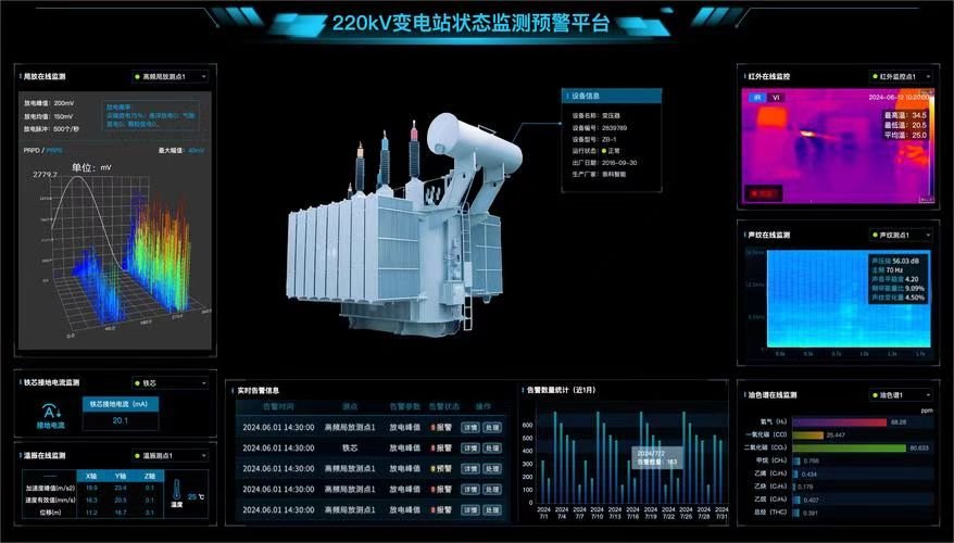
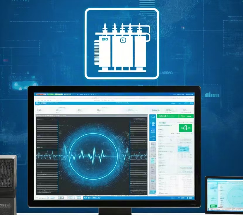
Deciding whether to repair, retrofit, or replace a transformer is a high-stakes judgment. If done too early, it wastes capital. Too late, and it invites catastrophic failure. While age, cost, and system needs play important roles, nothing delivers clearer insight than condition assessment tools. These diagnostics don’t guess—they measure. Using real-time data and standardized benchmarks, they help operators understand the actual state of a transformer, detect hidden faults, and predict remaining service life. In essence, they turn maintenance decisions from guesswork into science.
Condition assessment tools provide critical data on insulation health, dielectric strength, thermal stress, fault gases, moisture levels, partial discharge activity, and mechanical stability—empowering asset managers to make informed decisions about transformer repair, upgrade, or replacement. These tools support proactive strategies by identifying early signs of degradation, benchmarking transformer condition, and quantifying failure risk. Their use aligns with best practices outlined in IEC 60076-19, IEEE C57 standards, and ISO 55000 asset management frameworks.
Integrating condition assessment into lifecycle decisions ensures performance, safety, and investment optimization—without costly surprises.
Condition assessment tools provide objective data that helps determine whether a transformer should be repaired, retrofitted, or replaced.True
Diagnostics like DGA, furan testing, thermal imaging, and insulation resistance give insights into actual transformer health.
Visual inspection alone is sufficient for evaluating a transformer's condition.False
Visual checks can miss internal faults. Only detailed diagnostics like DGA and IR analysis reveal insulation, thermal, and electrical issues.
Modern condition monitoring systems can predict transformer failure trends using real-time data.True
IoT-based systems track load, heat, and fault gases, allowing predictive maintenance based on condition rather than fixed schedules.
Key Transformer Condition Assessment Tools and What They Reveal
1. Dissolved Gas Analysis (DGA)
The gold standard for detecting internal arcing, overheating, and insulation degradation.
| Gases Monitored | Fault Indicated |
|---|---|
| Hydrogen (H₂) | Partial discharges |
| Acetylene (C₂H₂) | Arcing |
| Methane (CH₄), Ethylene (C₂H₄) | Thermal faults |
| Carbon monoxide (CO), CO₂ | Paper insulation decay |
| Threshold | Implication |
|---|---|
| H₂ > 500 ppm | Partial discharge risk |
| C₂H₂ > 50 ppm | Internal arcing present |
| CO > 1000 ppm | Aging cellulose, possible end-of-life |
Multi-gas DGA monitors can provide continuous, real-time alerts for early intervention.
2. Furan Analysis
Evaluates degradation of solid cellulose insulation (the irreversible aging marker).
| Furan Level | Paper Condition |
|---|---|
| <500 ppb | Healthy insulation |
| 500–2000 ppb | Mid-aging |
| >2500 ppb | Critical aging, near end-of-life |
Often paired with Degree of Polymerization (DP) measurements:
- DP < 200 = insulation mechanically unreliable
3. Moisture-in-Oil Measurement
High moisture compromises dielectric strength and accelerates aging.
| Moisture (ppm) | Action Needed |
|---|---|
| <20 ppm | Good condition |
| 20–40 ppm | Monitor frequently |
| >40 ppm | Drying or oil replacement required |
Modern online moisture sensors allow dynamic monitoring, especially important in humid climates or ester oil systems.
4. Partial Discharge (PD) Detection
Identifies internal or surface discharges within insulation systems.
| PD Type | Detected By |
|---|---|
| Internal discharges | UHF or acoustic sensors |
| Surface discharges | Corona camera or ultrasonic |
| Cable terminations | TEV sensors |
| Result | Recommended Action |
|---|---|
| PD detected >1000 pC | Investigate cause and location |
| No PD activity | Safe to continue operation |
Persistent PD is a pre-failure condition that often precedes catastrophic failure.
5. Insulation Resistance (IR) and Polarization Index (PI)
Key indicators of dielectric integrity.
| Metric | Healthy Value |
|---|---|
| IR | >1 GΩ |
| PI | >2.0 |
If IR <100 MΩ or PI <1.5, insulation may be contaminated or aged.
6. Thermal Imaging and Hot-Spot Detection
Used to locate overloaded windings, cooling failures, or blocked radiators.
| Observation | Interpretation |
|---|---|
| Hotspot >120°C | Load exceeds design, internal insulation risk |
| Uneven radiator temps | Blocked or leaking units |
| Fan/motor hotspots | Motor failure or poor airflow |
Paired with load data, thermal imaging informs cooling system upgrades or de-rating.
7. Load and Voltage Monitoring
IoT-based systems track real-time loading and stress events:
| Indicator | Insight |
|---|---|
| Load >90% for >12 hrs/day | Consider upsizing or enhancing cooling |
| Voltage swings >±5% | May indicate tap changer or grid issues |
Supports capacity planning and guides retrofit or replacement timelines.
8. Acoustic/Vibration Analysis
Used for detecting core loosening, tank resonance, and mechanical damage.
| Symptom | Potential Cause |
|---|---|
| High noise, irregular frequency | Core vibration or winding resonance |
| Spike during LTC operation | Tap changer arc or misalignment |
Mechanical issues degrade insulation and increase fault risk if not addressed.
How Condition Data Guides Lifecycle Decisions
| Data Insight | Recommendation |
|---|---|
| Furan >2500 ppb + DGA arcing | Replace transformer |
| Moisture >40 ppm + IR <100 MΩ | Retrofit with oil treatment, gasket sealing |
| PD >1000 pC but healthy insulation | Install continuous monitoring, plan repair |
| Good oil, IR, and DGA results at 20 years | Continue operation or light retrofit |
| Cooling hotspots + high load | Retrofit fans or ODAF system |
Combined with risk matrices, these assessments inform asset prioritization, budget allocation, and replacement scheduling.
Visual: Transformer Health Scorecard (Sample Output)
| Assessment Tool | Result | Status |
|---|---|---|
| DGA | Low gases | ✅ Normal |
| Furan | 1900 ppb | ⚠ Aging |
| IR | 750 MΩ | ✅ Strong |
| PD | 0–50 pC | ✅ Clean |
| Thermal Imaging | Even temps | ✅ Stable |
| Load Profile | 85% average | ⚠ Approaching threshold |
→ Recommendation: Retrofit LTC + continue monitoring for 5 more years.
Benefits of Using Condition Assessment Tools
| Benefit | Value |
|---|---|
| Objective data | No guesswork in decision-making |
| Early fault detection | Prevent catastrophic failures |
| Prioritized maintenance | Invest where it matters most |
| Lifecycle extension | Targeted upgrades instead of replacements |
| Compliance readiness | Auditable records and test logs |
These tools align with asset management standards like ISO 55001 and regulatory frameworks including IEC 60076-19 and IEEE C57.143.
Conclusion
Deciding whether to repair, retrofit, or replace a transformer depends on a careful evaluation of technical, financial, and operational factors. Repair is suitable for isolated faults, retrofitting extends life and modernizes performance, while replacement becomes inevitable for aged, unsafe, or underperforming units. A proactive condition assessment program enables data-driven decisions—ensuring transformer assets continue to serve reliably and efficiently throughout their lifecycle.
FAQ
Q1: When should a transformer be repaired instead of replaced?
A1: Choose repair when:
The issue is minor or localized, like a gasket leak, bushing crack, or terminal fault
Oil contamination can be corrected by filtration or dehydration
The transformer is relatively young (under 20 years) with no critical insulation damage
Repair costs are significantly lower than replacement and don't affect future reliability
Repairs offer a cost-effective, fast solution when downtime must be minimized.
Q2: When is retrofitting or upgrading the best option?
A2: Retrofitting is ideal when:
The transformer is mechanically sound but electrically outdated
There’s a need for modern protection systems, digital monitoring, or cooling upgrades
Regulatory compliance requires lower losses or eco-friendly fluids
You want to extend life without full replacement (typically 20–35 years old units)
It’s a great strategy to boost performance, efficiency, and safety with lower investment than new equipment.
Q3: When should a transformer be replaced entirely?
A3: Full replacement is recommended when:
The unit is beyond 30–40 years old with degraded insulation and core losses
Multiple failures or recurring faults increase maintenance costs
It can no longer meet load demand or modern standards
DGA results or IR tests show irreversible internal damage
Efficiency losses and downtime risks outweigh repair costs
Replacement ensures long-term reliability and improved efficiency.
Q4: How do I decide between repair, retrofit, and replacement?
A4: Consider these factors:
Age and condition of core and windings
Test results (e.g., DGA, IR, SFRA, winding resistance)
Cost vs. benefit (short-term fix vs. long-term ROI)
Load growth or technology changes
Environmental and regulatory obligations
A condition assessment and lifecycle analysis by experts helps make the best call.
Q5: Are there tools or standards to guide transformer lifecycle decisions?
A5: Yes. Key resources include:
IEEE C57.140 – Guide for evaluating and reconditioning transformers
ISO 55000 – Asset management lifecycle planning
Doble and NETA test standards – For diagnostics and aging assessment
OEM condition monitoring systems – Offering real-time health indices
These tools support data-driven decisions that minimize risk and optimize capital planning.
References
"Transformer Repair vs Replace Guide" – https://www.electrical4u.com/transformer-repair-or-replace
"IEEE C57.140: Evaluation of Liquid-Immersed Transformers" – https://ieeexplore.ieee.org/document/8965624
"Doble: Condition-Based Transformer Lifecycle Analysis" – https://www.doble.com/transformer-lifecycle-support
"NREL: Asset Lifecycle Decision Tools for Utilities" – https://www.nrel.gov/docs/transformer-lifecycle-analysis.pdf
"ScienceDirect: Transformer Maintenance vs Replacement Analysis" – https://www.sciencedirect.com/transformer-repair-vs-replace-study