When purchasing a power transformer, understanding what is typically included in the supply scope is essential for planning, installation, and operation. A standard transformer package often comprises core electrical components and essential accessories required for safe and reliable performance. This article outlines the key components usually delivered with a power transformer.
What Are Transformer Core and Windings, and Why Are They Critical?
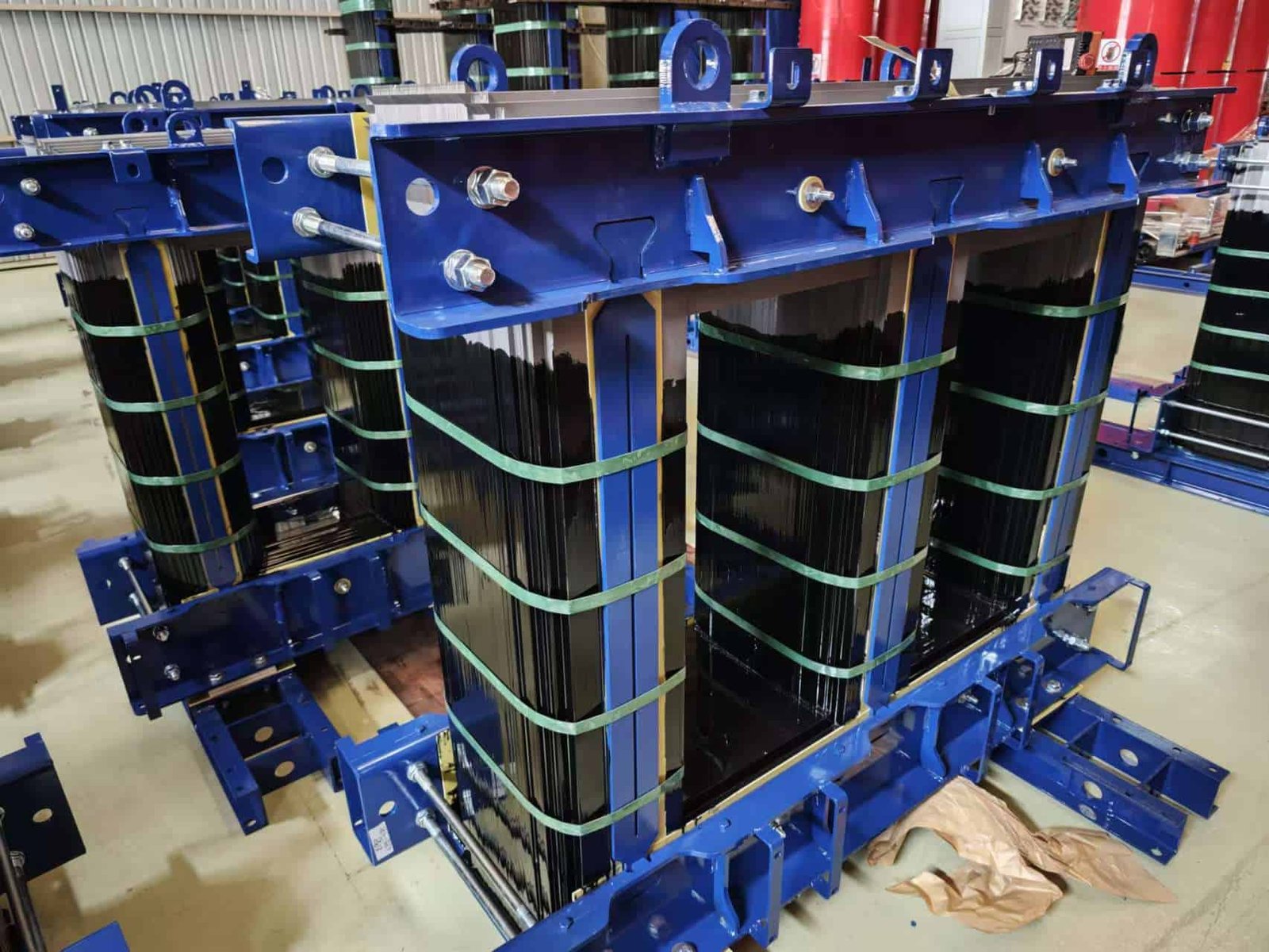
In any transformer, the core and windings form the fundamental working heart of the system. Their performance determines not only how efficiently energy is transferred but also how well the transformer withstands electrical, thermal, and mechanical stresses over time. If either of these components fails or degrades, it leads to inefficiencies, overheating, insulation breakdown, or even catastrophic faults. Whether you’re designing, maintaining, or upgrading a transformer, a deep understanding of the core and winding design is essential to ensure reliability and performance.
The core and windings are the central components of a transformer: the core provides a low-reluctance path for magnetic flux, while the windings carry electrical current and induce voltage via electromagnetic induction. The core is typically made of laminated silicon steel to minimize eddy current and hysteresis losses, and the windings are made of copper or aluminum for high conductivity. Their design, material quality, and insulation systems directly affect the transformer’s efficiency, load capacity, and service life.
Optimizing both core and winding design is the key to transformer efficiency and durability.
Transformer windings carry the electrical current and create the magnetic field in a transformer.True
Windings are the active electrical conductors that induce and transfer voltage based on Faraday’s law of electromagnetic induction.
Transformer cores are typically made of laminated steel to reduce losses.True
Laminations reduce eddy currents and hysteresis losses in the core, improving efficiency and minimizing heating.
Winding material has no effect on transformer performance.False
Winding material affects resistance, heat generation, and conductivity; copper windings offer lower losses than aluminum.
1. Transformer Core: Magnetic Flux Pathway
The core’s main role is to concentrate and guide the magnetic flux generated by the primary winding to the secondary winding with minimal losses.
| Attribute | Purpose |
|---|---|
| Material | High-grade silicon steel or amorphous steel |
| Construction | Laminated sheets (0.23–0.35 mm) to reduce eddy currents |
| Design | Core-type (winding surrounds core) or shell-type (core surrounds winding) |
| Magnetic Permeability | Determines how effectively magnetic flux is transmitted |
| Loss Minimization | Minimizes hysteresis and eddy current losses |
Flux Flow:
Primary Current → Magnetic Field in Core → Induces Voltage in Secondary WindingCore Losses:
- Hysteresis Loss: Proportional to frequency and magnetic flux density
- Eddy Current Loss: Proportional to the square of frequency and thickness of lamination
| Core Type | Efficiency | Application |
|---|---|---|
| CRGO Steel (Cold Rolled Grain Oriented) | High | Power transformers |
| Amorphous Metal | Very high | Energy-efficient distribution transformers |
| CRNGO | Medium | Low-cost, small units |
2. Transformer Windings: Electrical Workhorse
Windings are the electrical coils wrapped around the core that carry the input (primary) and output (secondary) current. They enable voltage transformation based on Faraday’s law of induction.
| Winding Type | Role |
|---|---|
| Primary | Receives input voltage, generates magnetic field |
| Secondary | Induced by magnetic field, delivers transformed output voltage |
| Parameter | Copper Winding | Aluminum Winding |
|---|---|---|
| Conductivity | High (58 MS/m) | Lower (35 MS/m) |
| Size | Compact | Larger cross-section required |
| Weight | Heavier | Lighter |
| Cost | Higher | Lower |
| Mechanical Strength | Better | Moderate |
| Usage | Large/critical transformers | Economical designs |
Winding Techniques:
- Layer Winding: Uniform layers for small/medium voltages
- Disc Winding: High-voltage applications; good cooling
- Helical Winding: High-current, low-voltage usage
Table: Key Properties of Transformer Core and Windings
| Property | Core | Windings |
|---|---|---|
| Function | Magnetic flux path | Voltage induction and transfer |
| Material | CRGO, Amorphous steel | Copper, Aluminum |
| Electrical Role | None (magnetic only) | Carries AC current |
| Design Objective | Low core loss | Low copper loss and heating |
| Cooling Consideration | Lower heat generation | Higher heat → needs oil/air cooling |
| Failure Risk | Mechanical vibration, delamination | Short-circuit stress, insulation breakdown |
3. Thermal and Mechanical Considerations
Both components are subject to electro-mechanical forces and thermal expansion during load cycles.
Winding Failures:
- Hot spots from poor oil circulation
- Insulation breakdown from high voltage spikes
- Short-circuits from electromagnetic forces
Core Failures:
- Vibration-induced noise (magnetostriction)
- Core bolt insulation failure → circulating currents
- Saturation from overvoltage → increased core loss
Proper design must consider:
- Oil duct spacing for heat dissipation
- Impulse withstand for lightning and switching surges
- Use of clamping structures to prevent winding movement during faults
4. Core and Winding Optimization for Efficiency
| Design Aspect | Improvement Strategy |
|---|---|
| Winding resistance | Minimize length, use copper |
| Leakage reactance | Optimize spacing between coils |
| Core flux density | Operate below saturation point (1.6–1.8 T for CRGO) |
| Cooling efficiency | Use oil ducts, disc windings, and forced cooling |
| Insulation system | Use thermally upgraded paper, pressboard, and Nomex |
Diagram: Electromagnetic Action of Core and Windings
[Primary Winding]
       ↓ (AC Current)
 → Magnetic Flux in Core →
       ↑
[Secondary Winding]
       ↓ (Induced Voltage Output)
The core ensures efficient flux linkage; the winding handles current flow and voltage transformation.
5. Real-World Failure Example: Core and Winding Fault
| Location | Large Utility Transformer (North America) |
|---|---|
| Event | Lightning surge damaged winding insulation |
| Root Cause | Poor impulse design, weak winding clamping |
| Secondary Effect | Core grounded → circulating current and overheating |
| Result | Transformer failure, service outage |
| Lesson | Design must ensure both mechanical and dielectric strength in windings and electrical isolation in core assemblies |
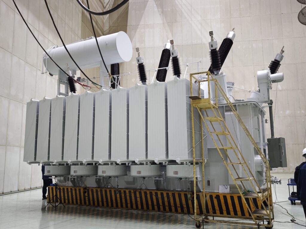
What Are the Main Tank and Conservator in a Transformer, and What Are Their Functions?
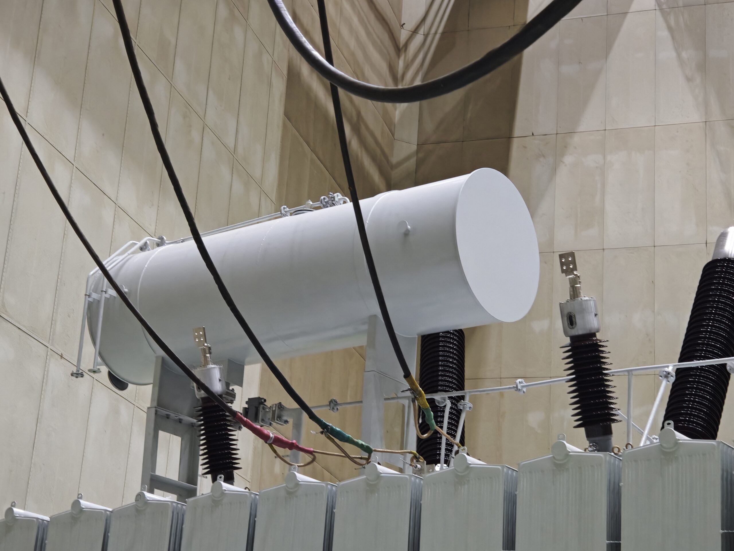
A power transformer is a highly engineered system, and its operational reliability depends heavily on its mechanical and oil management components—especially the main tank and the conservator. While often overlooked compared to the windings or core, these two components are vital for housing, protecting, and stabilizing the internal transformer environment. Failure or mismanagement of these elements can lead to insulation breakdown, overheating, and catastrophic oil loss, making it critical for operators, designers, and maintenance teams to fully understand their purpose and care.
The main tank of a transformer houses the active parts—core, windings, insulation, and oil—while the conservator tank provides an expansion chamber for the transformer oil as it heats and cools. The main tank is built to be oil-tight and strong enough to support the internal components and withstand pressure surges, whereas the conservator, mounted above the main tank, ensures the oil volume changes do not allow air or moisture to enter the transformer. Together, they help maintain dielectric strength, cooling efficiency, and system longevity.
Without the main tank and conservator working together, the transformer’s thermal and insulation systems would fail under normal operation.
The main tank holds the core and windings immersed in transformer oil.True
It is the primary structural enclosure that contains the transformer’s active parts and dielectric fluid.
The conservator tank is only needed in dry-type transformers.False
Dry-type transformers do not use oil and thus have no conservator. Oil-filled transformers require a conservator for oil expansion control.
Silica gel breathers in the conservator system help prevent moisture ingress.True
They absorb moisture from atmospheric air drawn in during oil contraction, preserving insulation integrity.
1. Main Tank: The Structural and Protective Enclosure
The main tank of an oil-immersed transformer is a hermetically sealed, heavy-duty enclosure designed to:
- Hold the active parts (core, coils, insulation)
- Contain the insulating and cooling oil
- Withstand internal pressure and vacuum
- Support external components like bushings, radiators, and tap changers
Construction Materials:
| Component | Material |
|---|---|
| Tank body | Mild steel, welded |
| Stiffeners | Steel angle/channel |
| Gaskets & seals | Oil-resistant rubber |
Key Functional Requirements:
- Leak-proof for oil retention
- Mechanically rigid to prevent deformation under thermal cycles
- Corrosion-resistant, often with galvanized or epoxy coatings
- Safe under faults, designed with pressure relief devices
2. Conservator Tank: Oil Expansion Management System
Oil expands when heated and contracts when cooled. Without a flexible volume system, internal pressure would stress the tank seals or allow air to mix with the oil, degrading its insulating and cooling properties.
The conservator tank is mounted above the main tank and connected via oil piping. Its function is to:
- Accommodate oil volume fluctuations
- Isolate main tank oil from the atmosphere
- Enable air exchange through a moisture-controlled breather
Types of Conservator Systems:
| Type | Description | Application |
|---|---|---|
| Open conservator | Air directly contacts oil surface | Older designs |
| Sealed conservator | Uses air bladder or rubber diaphragm | Modern transformers |
| Nitrogen-pressurized | Inert gas replaces air | Sensitive or fire-critical areas |
Diagram: Transformer Main Tank and Conservator Setup
[Atmospheric Air]
    ↓ (Through silica gel breather)
[Conservator Tank]
    ↓ (Oil volume expands/contracts)
[Main Tank] ← Core + Windings + Oil
    ↓
[Cooling Radiators or Fans]
The conservator keeps oxygen and moisture away from the oil inside the main tank, preserving insulation.
3. Silica Gel Breather: Moisture Barrier in Air Exchange
When the oil contracts, air is drawn into the conservator. The silica gel breather prevents moisture-laden air from entering and contaminating the oil.
| Feature | Function |
|---|---|
| Silica gel beads | Absorb water vapor from incoming air |
| Color indicator | Changes (blue → pink) as saturation occurs |
| Breather oil trap | Prevents direct air rush and further contamination |
Routine maintenance of silica gel is essential to maintain transformer dryness.
4. Oil Expansion and Contraction: Thermal Dynamics
| Temperature Condition | Oil Behavior | Conservator Role |
|---|---|---|
| Load increase (hot) | Oil expands | Pushes oil into conservator |
| Load decrease (cool) | Oil contracts | Draws oil back from conservator |
| Ambient fluctuation | Daily cycles | Maintains internal pressure balance |
Why it Matters:
- Prevents vacuum formation that could collapse tank walls
- Avoids air bubbles forming inside the windings
- Reduces oxidation, which causes sludge and acidity
5. Main Tank and Conservator Safety Devices
| Device | Location | Function |
|---|---|---|
| Buchholz Relay | Between conservator and main tank | Detects gas buildup or oil surge (fault) |
| Oil Level Gauge | Conservator | Shows current oil volume |
| Pressure Relief Valve | Main tank | Releases pressure during faults |
| Explosion Vent | Main tank (some designs) | Prevents rupture under extreme pressure |
| Oil Sampling Valve | Main tank base | For dielectric and moisture testing |
6. Design Standards and Codes
| Standard | Relevance |
|---|---|
| IEC 60076 | Transformer general design, tank and conservator standards |
| IEEE C57.12.00 | Enclosure requirements, fault protection |
| ISO 12944 | Paint and corrosion protection for tanks |
| ASME Section VIII | Pressure vessel considerations (where applicable) |
Compliance ensures safety, reliability, and performance in harsh environmental or load conditions.
7. Maintenance Recommendations
| Task | Frequency | Importance |
|---|---|---|
| Inspect for leaks | Monthly | Prevents oil loss and contamination |
| Check oil level | Monthly | Identifies excessive consumption or internal issues |
| Replace silica gel | Biannually or when saturated | Maintains dry air entry |
| Paint/coating inspection | Annually | Prevents corrosion of tank shell |
| Oil testing | Annually | Detects early aging, moisture, or oxidation |
Failing to maintain the conservator system can lead to premature insulation breakdown and reduced transformer life.
What Is a Transformer Cooling System and How Does It Work?
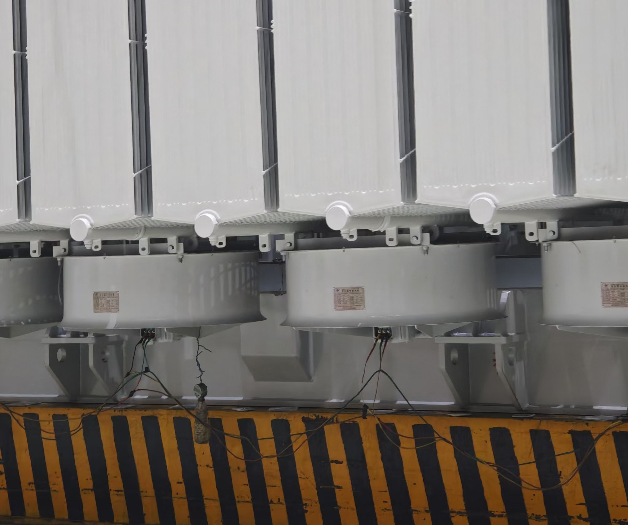
When a transformer operates under electrical load, it inevitably generates heat—primarily due to losses in the core (iron losses) and windings (copper losses). If this heat isn’t removed efficiently, internal temperatures can rise rapidly, degrading insulation, reducing performance, and shortening the service life. That’s where the cooling system comes into play. Whether using natural convection, forced air, or pumped oil circulation, the cooling system ensures the transformer remains within safe thermal limits during operation.
A transformer cooling system is a thermal management arrangement that dissipates heat generated during transformer operation to maintain temperature within safe operating limits. Depending on the size and application, cooling can be achieved through natural air (AN), oil-immersed air-cooled (ONAN), forced oil-air systems (ONAF), or even water-cooled systems (OFWF). Radiators, fans, pumps, and cooling ducts are all integrated to extract and transfer heat away from the core and windings, preserving insulation integrity and extending service life.
Effective cooling is vital for safe, efficient, and long-lasting transformer operation.
Transformer cooling systems help maintain operating temperature within safe limits.True
Cooling systems dissipate heat generated by core and copper losses, preserving insulation and performance.
Air-cooled and oil-cooled transformers use the same cooling principles.False
Air-cooled transformers rely on ambient air convection, while oil-cooled systems use oil as a heat transfer medium.
Fans and pumps can improve transformer cooling efficiency under high load.True
Forced cooling increases heat dissipation capacity, allowing for greater load handling without overheating.
1. Why Cooling Is Necessary in Transformers
Transformers operate under high electrical load, and heat is produced mainly due to:
- Copper (I²R) losses in windings
- Core losses (hysteresis and eddy currents)
- Stray losses in tank and structural components
If heat isn’t removed:
- Insulation degrades, leading to dielectric failure
- Oil oxidizes, losing dielectric strength
- Hot spots develop, reducing lifespan
Each 6°C increase in operating temperature halves the insulation life.
2. Cooling Classifications According to IEC 60076 and IEEE C57
| Code | Meaning | Description |
|---|---|---|
| AN | Air Natural | Air-cooled dry-type transformers |
| AF | Air Forced | Fans blow air over windings (dry-type) |
| ONAN | Oil Natural Air Natural | Oil circulates naturally; cooled by ambient air |
| ONAF | Oil Natural Air Forced | Fans blow air over radiators |
| ODAF | Oil Directed Air Forced | Oil is pumped; cooled by forced air |
| OFWF | Oil Forced Water Forced | Oil pumped to water heat exchanger |
The larger the transformer, the more likely it will use oil-based, forced cooling systems.
3. Components of Transformer Cooling Systems
| Component | Function |
|---|---|
| Radiators | Surface area for heat dissipation from oil |
| Cooling Fins/Tubes | Compact heat exchange elements |
| Fans | Forced airflow over radiators to accelerate cooling |
| Oil Pumps | Circulate oil faster to remove heat quickly |
| Heat Exchangers | Water-cooled or air-cooled external cooling |
| Cooling Ducts | Channels within windings for oil or air flow |
| Temperature Sensors | Monitor winding and oil temperatures |
| Relays and Alarms | Trigger on over-temperature or fan/pump failure |
Diagram: ONAN vs. ONAF Cooling Path
[ONAN Cooling]
   Core → Oil heats up → Rises to top → Radiators → Cools down → Sinks to bottom → Core

[ONAF Cooling]
   Same as ONAN +
   → Fans blow air across radiators → Accelerated heat loss
4. Natural Cooling vs. Forced Cooling: Comparison
| Feature | ONAN (Natural) | ONAF (Forced) |
|---|---|---|
| Oil Circulation | Natural convection | Natural + Fans |
| Cooling Capacity | Standard | 30–40% higher |
| Cost | Lower | Higher (fans, wiring) |
| Noise | Low | Moderate |
| Maintenance | Minimal | Requires fan checks, relay calibration |
| Typical Rating | Up to 10 MVA | 10 MVA and above |
5. Advanced Cooling: ODAF and OFWF Systems
For high-power transformers (>60 MVA) or industrial environments:
| System | Method | Advantages |
|---|---|---|
| ODAF | Oil is pumped and directed through windings and ducts | Excellent temperature control, suitable for overload |
| OFWF | Oil and water circuits with plate heat exchangers | Efficient in space-constrained or indoor settings |
| ODWF | Oil and water forced cooling with directed oil flow | Used in large utility or generator step-up transformers |
These systems often feature backup fans/pumps, automation, and SCADA integration.
6. Cooling System Monitoring and Protection
| Device | Purpose |
|---|---|
| Winding Temp Indicator (WTI) | Measures calculated winding hot spot |
| Oil Temp Indicator (OTI) | Measures top oil temperature |
| Buchholz Relay | Detects gas and oil surges (in conservator systems) |
| Fan/Pump Relays | Start cooling based on temperature thresholds |
| Trip Contacts | Shut down transformer during overheating |
Cooling failures can lead to flashover, oil degradation, or core damage.
7. Maintenance Guidelines for Cooling Systems
| Task | Frequency | Objective |
|---|---|---|
| Fan/pump inspection | Quarterly | Check bearing noise, wiring |
| Radiator cleaning | Biannually | Remove dust/debris for airflow efficiency |
| Oil flow check (ODAF) | Annually | Confirm proper circulation |
| Heat exchanger flushing (OFWF) | Annually | Remove scale and sludge |
| Temperature relay calibration | Annually | Ensure accurate protection triggers |
Thermal imaging can also help detect blocked ducts, non-functioning fans, or uneven heating.
Table: Cooling Capacity Enhancements by System
| Cooling Method | Base Capacity | Increased Rating |
|---|---|---|
| ONAN only | 100% | – |
| ONAN + ONAF | 100% | Up to 140% |
| ONAF + ODAF | 100% | Up to 160% |
| ODAF + OFWF | 100% | Up to 200% or more |
Transformer ratings are often dual-specified (e.g., 100 MVA ONAN / 140 MVA ONAF).
8. Energy-Efficient and Intelligent Cooling
Modern designs integrate:
- Variable speed fans/pumps for energy savings
- SCADA-controlled cooling automation
- IoT sensors for real-time temperature and oil analysis
- Artificial intelligence for predictive cooling and overload management
These technologies optimize cooling efficiency, reduce operating costs, and enhance safety.
What Are On-Load and Off-Load Tap Changers, and How Do They Work in Transformers?
Tap changers are critical accessories in power transformers, enabling operators to adjust output voltage to maintain system stability and performance despite fluctuations in input voltage or load. Depending on the system requirements, transformers can be equipped with on-load tap changers (OLTC) or off-load tap changers, each designed for specific operating conditions and grid responsibilities. Understanding their construction, function, and application is essential for specifying the right transformer and managing voltage regulation effectively.
Tap changers are transformer devices that adjust the number of turns in the winding to regulate the voltage ratio. An off-load tap changer allows voltage adjustment only when the transformer is de-energized, whereas an on-load tap changer (OLTC) enables voltage changes under load without interrupting power supply. OLTCs are used in critical grid or industrial systems requiring real-time voltage regulation, while off-load tap changers are typical in simpler or lightly loaded transformers where infrequent adjustment is acceptable.
Tap changers ensure voltage consistency and adaptability, improving power quality and transformer flexibility.
Tap changers change the number of active winding turns to adjust transformer output voltage.True
By altering tap connections on the winding, they change the turns ratio, regulating voltage.
Off-load tap changers allow voltage regulation during transformer operation.False
Off-load tap changers must only be operated when the transformer is de-energized to avoid arcing and damage.
OLTCs use diverter switches and arc suppression to change taps under load without interruption.True
OLTCs are designed to handle load current using transition resistors or reactors to suppress arcing.
1. Purpose and Function of Tap Changers
Transformers operate based on a fixed turns ratio, but voltage conditions are rarely constant due to:
- Grid fluctuations
- Load variations
- System expansion
Tap changers alter the effective number of winding turns, changing the output voltage to suit the system requirement.
Basic Tap Changer Principle:
Turns Ratio = N_primary / N_secondary

Adjusting N_secondary (via taps) → Adjusts output voltage (V_out)
2. Comparison: On-Load vs. Off-Load Tap Changers
| Feature | Off-Load Tap Changer | On-Load Tap Changer (OLTC) |
|---|---|---|
| Operating Condition | Only when transformer is off | During live operation |
| Location | Typically on HV winding | On HV winding (series/neutral end) |
| Arc Management | Not needed | Uses resistors/reactors to suppress arc |
| Cost | Lower | Higher |
| Complexity | Simple, manual/step switch | Complex, motor-driven with control gear |
| Maintenance | Minimal | Regular oil/filter changes, contact checks |
| Application | Distribution transformers, static loads | Grid transformers, industrial loads, power stations |
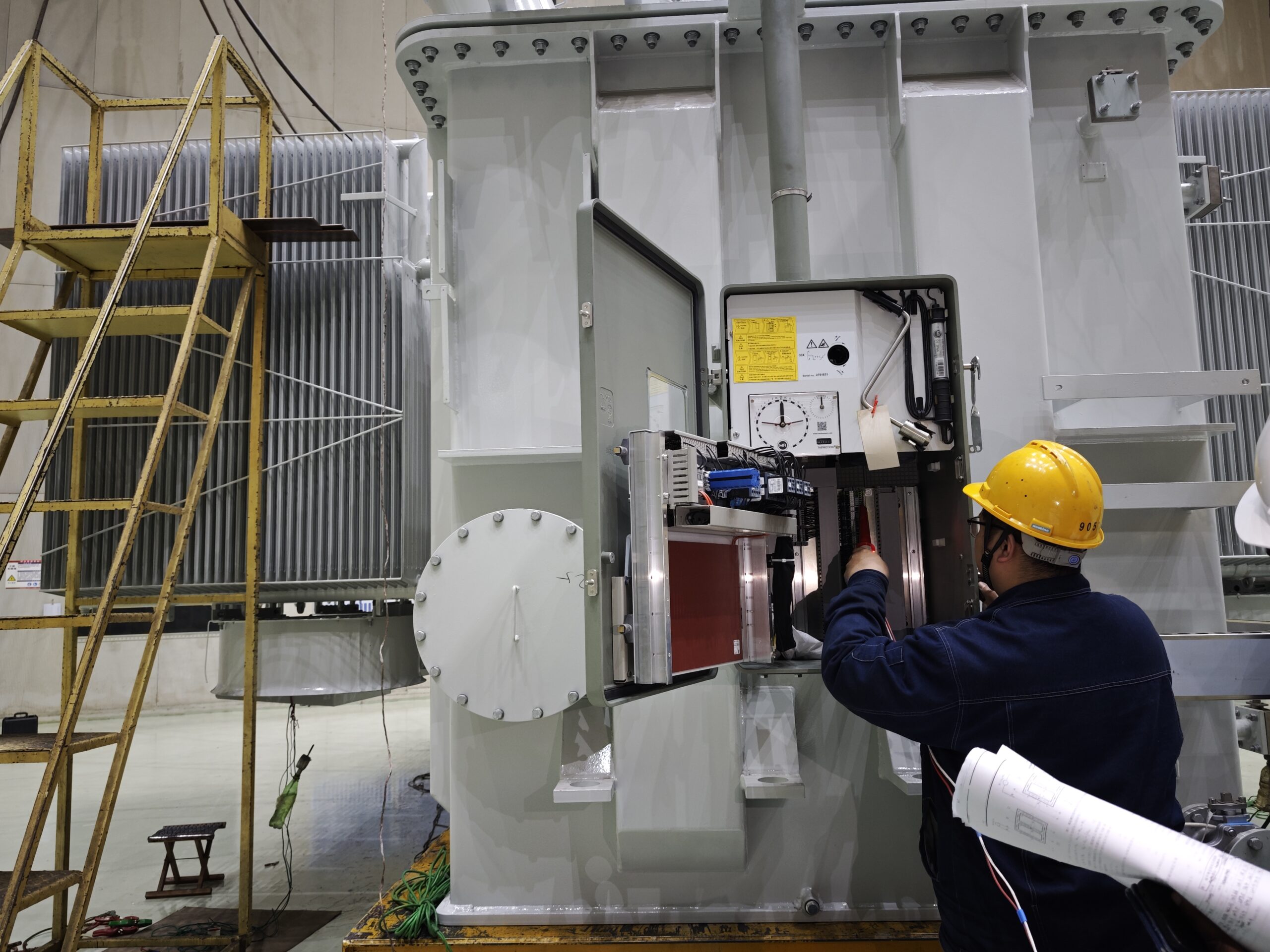
3. How On-Load Tap Changers Work
OLTCs are built to change taps without disconnecting power. They are motor-operated, housed in a separate oil compartment or inside the main tank.
OLTC Switching Sequence:
- Motor drive initiates tap change
- Diverter switch selects new tap
- Transition resistors/reactors handle overlap current
- Arc extinguished during transition
- Main contacts transfer full current to new tap
OLTC Design Variants:
| Type | Description |
|---|---|
| Resistive type | Uses resistors to suppress arcs |
| Reactive type | Uses reactors for smoother switching (used in very large transformers) |
| Vacuum OLTC | Uses vacuum interrupters instead of oil for arc quenching |
Diagram: OLTC Internal Configuration
[Motor Drive Unit]
     ↓
[Tap Selector] → [Diverter Switch (Arc Control)]
     ↓
[Tap Windings] → Output Voltage Regulated
4. Off-Load Tap Changer Design and Operation
These are manually operated or motorized rotary switches, located on the high-voltage winding, that:
- Allow ±5% to ±10% adjustment in steps (e.g., ±2.5% per tap)
- Require transformer shutdown to change taps
- Have no arc quenching mechanism
| Component | Function |
|---|---|
| Tap positions | Pre-defined voltage steps |
| Manual switch or handle | Engages the desired tap |
| Safety interlock | Prevents operation under load |
Applications:
- Pole-mounted transformers
- Pad-mounted distribution units
- Voltage-regulated industrial equipment
5. Tap Range and Voltage Regulation Capabilities
| Tap Configuration | Voltage Range |
|---|---|
| ±5% in 2 steps | ±2.5% per step |
| ±10% in 5 steps | ±2% per step |
| ±16 steps OLTC | ±16% in 1.25% steps |
Larger systems use finer tap steps to ensure stable voltage in real-time operations.
6. Maintenance and Monitoring of OLTCs
Because OLTCs switch under load, they undergo electrical wear and oil contamination.
| Maintenance Task | Frequency |
|---|---|
| Oil filtration or replacement | Every 2–4 years |
| Contact inspection/replacement | 5–10 years |
| Motor drive check | Annually |
| DGA of OLTC compartment oil | Annually |
Vacuum OLTCs significantly reduce oil degradation and maintenance needs.
Table: Tap Changer Selection Guide
| Transformer Rating | Preferred Tap Changer |
|---|---|
| ≤500 kVA | Off-load tap changer |
| 500 kVA – 5 MVA | Off-load or OLTC (depending on application) |
| >5 MVA | On-load tap changer (OLTC) |
| Grid/Utility Transmission | OLTC with SCADA interface |
| Renewable Integration | OLTC with fine tap resolution |
7. Modern Features in OLTC Systems
| Feature | Benefit |
|---|---|
| Remote tap changer control (RTCC) | Allows SCADA-based voltage regulation |
| Tap position indicators | Monitors position and history |
| Oil temperature sensors | Protects diverter chamber |
| Digital motor protection relays | Ensures reliable OLTC drive operation |
| IoT-enabled OLTCs | Condition monitoring, remote diagnostics |
Real-World Case Study: OLTC in Voltage-Sensitive Grid
| Scenario | Rural Utility Grid, India |
|---|---|
| Problem | Voltage variation from ±20% due to solar infeed |
| Action | Installed OLTC on 6.3 MVA substation transformer |
| Result | Maintained voltage at ±2%, improved power quality, reduced consumer complaints |
| Cost vs. Benefit | OLTC installation cost recovered in 2.5 years via improved grid reliability |
What Are Transformer Bushings and Terminals, and Why Are They Crucial to Safe Operation?
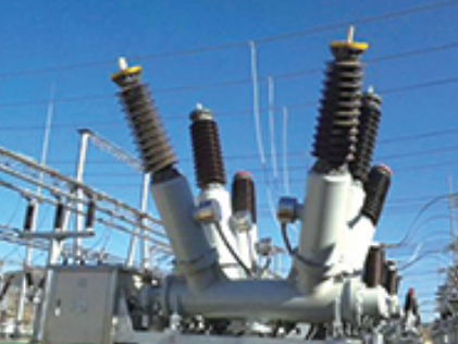
Every transformer—whether used in a utility grid, industrial plant, or renewable energy system—must interface with high-voltage lines or cables. This is where bushings and terminals come into play. These components are often under extreme electrical, thermal, and environmental stress. Improper selection, aging, or failure of these elements can lead to catastrophic faults, arc flash incidents, or fire. Yet, they’re sometimes overlooked during design or inspection. Understanding their purpose, types, and maintenance requirements is essential for system safety, reliability, and performance.
Transformer bushings are insulated structures that allow a high-voltage conductor to pass safely through the grounded tank of the transformer, while terminals are the connection points where cables or conductors are joined to the transformer. Bushings provide dielectric isolation and mechanical support for live conductors, and are typically made of porcelain or composite polymer. Terminals connect power lines to internal windings via the bushing conductor. Both must withstand high voltages, temperature variations, mechanical stress, and environmental exposure.
Transformer bushings and terminals are the first line of defense in safe power transfer—making them mission-critical components.
Transformer bushings provide insulated passage of conductors through the grounded transformer tank.True
Bushings allow safe electrical connection while preventing short circuits or ground faults through the tank wall.
Terminals are only used for grounding transformers.False
Terminals are used to connect incoming and outgoing high- or low-voltage conductors to transformer windings via bushings.
Porcelain and composite bushings are both used in modern transformers depending on voltage and environment.True
Porcelain offers durability and rigidity, while composite bushings are lighter, safer, and more resilient in polluted or seismic regions.
1. Purpose and Function of Bushings and Terminals
Bushings:
Bushings act as dielectric barriers that enable electrical conductors to safely pass through grounded transformer enclosures (like tanks or walls) without allowing short circuits or ground faults.
Terminals:
Terminals are the metallic ends where conductors (such as overhead lines or cables) are mechanically and electrically connected to the transformer windings through the bushing's central conductor.
| Function | Bushings | Terminals |
|---|---|---|
| Electrical | Isolate high voltage from ground | Transfer voltage to/from lines |
| Mechanical | Support conductor, resist vibrations | Clamp and secure conductors |
| Thermal | Withstand temperature changes | Handle current heating |
| Environmental | Seal against moisture, dirt | Prevent corrosion, arcing |
2. Types of Transformer Bushings
Based on Insulating Medium:
| Type | Description | Voltage Range | Application |
|---|---|---|---|
| Solid Porcelain | Ceramic shell with oil-impregnated paper (OIP) or resin core | Up to 245 kV | Traditional, utility-grade transformers |
| Resin-Impregnated Paper (RIP) | Solid insulation, no oil, environmentally safe | 36–800 kV | Substations, eco-sensitive areas |
| Resin-Bonded Paper (RBP) | Older technology, limited thermal endurance | <36 kV | Legacy installations |
| Hybrid/Composite | Polymer housing + RIP core | Up to 550 kV | Harsh outdoor conditions, seismic zones |
Based on Mounting Location:
| Mounting | Used For |
|---|---|
| Top-mounted (HV) | Primary voltage lines |
| Side-mounted (LV) | Secondary terminals or tertiary windings |
| Wall bushings | For transformer to switchgear or busbar exits |
Diagram: Cross-Section of a Transformer Bushing
[Line Terminal] → [Conductor] → [Solid/Oil Insulation] → [Porcelain/Polymer Housing] → [Tank Flange] → [Internal Connection to Winding]3. Transformer Terminals and Their Configurations
| Terminal Type | Description | Common Use |
|---|---|---|
| Bolt-type terminal | Copper/aluminum stud bolted to lug | Up to 33 kV |
| Clamp-type terminal | Mechanical clamp or compression fitting | Higher currents, large conductors |
| Plug-in terminal | For dry-type transformers or compact units | Indoor LV/MV applications |
| Air-insulated terminals | Bare metal in air | Standard installations |
| Cable box or GIS terminal | Enclosed, shielded terminal | Indoor or substation gas-insulated switchgear (GIS) systems |
Proper torque, conductor preparation, and moisture protection are essential for terminal integrity.
4. Dielectric and Thermal Ratings
Bushings Must Handle:
- Rated voltage and impulse withstand voltage
- Continuous current (e.g., 600–5000 A)
- Ambient and oil temperatures (-40 to +105°C)
- Pollution, UV, humidity, and seismic forces
| Voltage Class | Typical Bushing Type | Insulation Level |
|---|---|---|
| 11–33 kV | Solid porcelain, RBP | Basic |
| 66–145 kV | OIP, RIP | Medium |
| 220–550 kV | RIP, Composite | High |
| 800+ kV | SF₆ or hybrid gas-insulated bushings | Ultra-high voltage (UHV) applications |
5. Failure Modes and Warning Signs
| Component | Risk | Early Indicators |
|---|---|---|
| Bushing | Internal flashover, oil leakage, moisture ingress | Cracking, oil seepage, high partial discharge |
| Terminal | Loose connection, overheating, corona discharge | Hot spots, discoloration, audible noise, melting |
| Seals/Gaskets | Ageing, hardening, leakage | Oil weepage, pressure imbalance |
| Grounding/Shielding | Broken grading rings or corona shields | High RIV, RF noise, surface tracking |
6. Testing and Maintenance of Bushings and Terminals
| Test Type | Purpose | Interval |
|---|---|---|
| Capacitance (Tan δ/Power Factor) | Detect insulation degradation | Annually or during outages |
| Partial Discharge (PD) | Detect internal discharge activity | Online or offline testing |
| Infrared Thermography | Spot overheating at terminals | Quarterly or monthly |
| Visual Inspection | Look for cracks, oil seepage, corrosion | Monthly |
| Torque Check (Terminals) | Ensure secure electrical contact | Yearly or after line work |
Bushings should be replaced if capacitance increases by >10% or Tan δ exceeds 1%.
7. Modern Improvements: Composite and Smart Bushings
| Innovation | Benefit |
|---|---|
| Composite Insulated Bushings | Shatterproof, lightweight, better seismic performance |
| Smart bushings (with sensors) | Real-time temperature, partial discharge, and humidity monitoring |
| Silicone-encapsulated terminals | Improved corona protection |
| Condition Monitoring (DGA, PD sensors) | Prevent bushing failures through early alerts |
Table: Bushings and Terminals Selection Guide
| Application | Voltage Level | Recommended Bushing | Terminal Type |
|---|---|---|---|
| Distribution (rural) | ≤33 kV | Solid porcelain | Bolt-type |
| Industrial MV plant | 66–145 kV | RIP or OIP | Clamp-type |
| High-voltage substation | 220–400 kV | Composite RIP | GIS/cable box |
| UHV grid transformer | >500 kV | Gas-insulated SF₆ bushing | Specialized shielded terminals |
Real-World Case Study: Bushing Failure in 132 kV Substation
| Location | Southeast Asia |
|---|---|
| Event | OIP bushing failure caused fire and transformer outage |
| Root Cause | Moisture ingress + ageing of insulation paper |
| Indicator Ignored | Tan δ increase > 2.5%, visible oil weepage |
| Resolution | Replaced with RIP composite bushings |
| Benefit | Improved reliability, eliminated oil leak risks, lower maintenance |
What Protection, Monitoring, and Accessories Are Essential for Transformer Safety and Performance?

Transformers are among the most critical and expensive assets in power systems. Despite their robust design, they are vulnerable to faults caused by overloads, insulation failure, thermal stress, moisture ingress, and environmental disturbances. When these faults go undetected, they can escalate into catastrophic failures—causing fires, blackouts, or total equipment loss. That’s why protection, monitoring, and auxiliary systems are absolutely essential. These components not only extend the transformer’s service life but also provide early warning, enabling preventive maintenance and minimizing costly downtime.
Protection and monitoring systems for transformers include relays, sensors, alarms, and control devices that detect abnormal operating conditions such as overcurrent, overtemperature, gas accumulation, oil level fluctuation, and dielectric degradation. Accessories like Buchholz relays, pressure relief devices, surge arresters, and oil gauges serve as first responders to emerging faults. Digital monitoring systems further enable real-time diagnostics, remote alerting, and predictive analytics for transformer health management.
These systems form a comprehensive shield that ensures transformer safety, reliability, and efficiency across its operating life.
Buchholz relays detect gas accumulation and oil surges in transformer conservator systems.True
They are early warning devices for internal faults, such as insulation breakdown or winding failure.
Surge arresters protect transformers from internal short circuits.False
Surge arresters protect against external overvoltages, such as those caused by lightning or switching surges.
Monitoring accessories can help extend transformer service life by detecting problems early.True
Sensors and digital monitors identify anomalies before they escalate, enabling preventive maintenance.
1. Overview of Transformer Protection, Monitoring, and Accessories
| Category | Purpose |
|---|---|
| Protection Devices | Interrupt or isolate fault conditions to prevent damage |
| Monitoring Systems | Continuously track key health parameters |
| Accessories | Assist in mechanical and thermal operation, fault indication |
These systems ensure the transformer remains safe under abnormal conditions and performs optimally during normal operation.
2. Key Protection Devices in Transformers
2.1. Buchholz Relay
- Installed in conservator-equipped transformers (≥500 kVA)
- Detects gas buildup from insulation breakdown or arcing
- Responds to sudden oil surges caused by short circuits
| Function | Alarm Stage | Trip Stage |
|---|---|---|
| Gas accumulation | Yes | No |
| Oil surge (fast fault) | Yes | Yes |
2.2. Pressure Relief Device (PRD)
- Relieves sudden internal pressure from internal arcing or failure
- Prevents tank rupture
- Often triggers trip/alarm circuit
2.3. Temperature Relays
- Oil Temperature Indicator (OTI): Measures top oil temp
- Winding Temperature Indicator (WTI): Simulated via thermal sensors or current transformers
2.4. Differential Protection Relay
- Compares current entering and leaving transformer windings
- Detects internal winding faults such as phase-to-phase or turn-to-turn faults
| Relay Type | Function |
|---|---|
| 87T | Transformer differential protection |
| 51/50 | Overcurrent protection |
| 64REF | Restricted Earth Fault protection |
3. Monitoring Systems for Transformer Health
3.1. Oil Level and Oil Quality Sensors
- Float-type or capacitive probes detect low oil conditions
- DGA sensors monitor dissolved gases like H₂, CO, CH₄ (indicating insulation or core overheating)
3.2. Moisture and Water Content Monitors
- Important in hermetically sealed and conservator systems
- High water content reduces oil dielectric strength
3.3. Partial Discharge (PD) Sensors
- Detect micro-arcs or discharges inside insulation
- Predict cable or bushing failure
3.4. Smart Bushing Monitors
- Measure capacitance, power factor (Tan δ)
- Early warning of internal degradation or contamination
| Parameter | Ideal Range |
|---|---|
| Tan δ | <0.5% |
| Moisture (oil) | <30 ppm |
| H₂ (gas) | <150 ppm (alarm above this) |
4. Essential Accessories and Auxiliary Equipment
| Accessory | Function |
|---|---|
| Conservator Tank | Accommodates oil expansion |
| Silica Gel Breather | Prevents moisture ingress |
| Cooling Fans and Radiators | Dissipate heat from transformer oil |
| Magnetic Oil Level Gauge (MOG) | Indicates oil level in conservator |
| Tap Changer Position Indicator | Monitors OLTC tap setting |
| Drain/Filter Valves | Used for sampling and oil replacement |
| Explosion Vent | Safely relieves extreme pressure (older units) |
Diagram: Protection and Monitoring Layout in a Typical Transformer
[HV Terminal] → [Surge Arrester]
                ↓
[Main Tank] → [Core + Windings + Oil]
                ↓
[Cooling System] ← [Temperature Sensors (OTI, WTI)]
                ↓
[Conservator Tank] → [Buchholz Relay] → [Breather]
                ↓
[Monitoring Panel] → [DGA Sensor, Oil Level Gauge, Tap Indicator]
                ↓
[Protection Relay Panel] → [87T, PRD, Trip Contacts]
5. Digital and Remote Monitoring Enhancements
| Feature | Benefit |
|---|---|
| IoT-enabled sensors | Wireless real-time monitoring of oil, temperature, partial discharge |
| RTU/SCADA integration | Remote diagnostics, automatic alarms, analytics |
| Digital twin modeling | Predict future faults based on usage and environmental data |
| Mobile apps and cloud dashboards | Operator access from anywhere |
These upgrades transform preventive maintenance into predictive maintenance.
Table: Alarm and Trip Thresholds for Monitoring Systems
| Parameter | Alarm Threshold | Trip Threshold |
|---|---|---|
| Top oil temperature | 85°C | 95°C |
| Winding temperature | 95°C | 110°C |
| Oil level drop | 70% | 50% |
| Pressure rise | 0.5 bar | 1.0 bar |
| Buchholz gas volume | 0.5 L | 1.0 L (with surge) |
| Moisture content | >35 ppm | >50 ppm |
6. Maintenance Strategy for Protection and Monitoring Systems
| Task | Frequency | Purpose |
|---|---|---|
| Visual inspection of accessories | Monthly | Check for oil leaks, wear |
| Functional test of Buchholz relay | Quarterly | Verify contacts and oil surge operation |
| Calibration of OTI, WTI | Annually | Ensure accurate thermal protection |
| DGA and oil testing | Biannually | Identify chemical or electrical degradation |
| Surge arrester insulation check | Annually | Prevent overvoltage fault risk |
| Fan/pump motor check | Quarterly | Confirm cooling operation |
Neglecting these tasks increases transformer failure risk exponentially.
Real-World Case: Prevented Transformer Explosion via Early PRD Alarm
| Location | Northern Europe Industrial Substation |
|---|---|
| Event | Internal arc occurred due to insulation aging |
| Response | PRD activated; alarm triggered before tank rupture |
| Damage Prevented | Explosion, oil fire, substation blackout |
| Lesson | Protective accessories saved both equipment and operation continuity |
Conclusion
A standard power transformer supply package includes more than just the transformer tank—it delivers a complete, ready-to-operate system. This typically covers the core and windings, conservator, cooling apparatus, tap changers, bushings, and a suite of protection and monitoring devices. Depending on project needs, some optional items such as neutral grounding resistors, surge arresters, or transportation skids may also be included or requested. Understanding this scope ensures alignment between customer expectations and manufacturer deliverables.
FAQ
Q1: What components are typically included in the standard supply scope of a power transformer?
A1: A standard power transformer supply generally includes the following mechanical and electrical components:
Main transformer tank with core and windings
Conservator tank (for oil expansion)
On-load tap changer (OLTC) or off-circuit tap changer
High-voltage (HV) and low-voltage (LV) bushings
Radiators or cooling fins for heat dissipation
Oil level indicator, pressure relief device, silica gel breather
Buchholz relay (for gas accumulation detection)
Wheels/skids, lifting lugs, and grounding terminals
These parts are usually pre-assembled or shipped separately based on transport constraints.
Q2: Is the On-Load Tap Changer (OLTC) always part of the standard scope?
A2: Not always. OLTC is included if voltage regulation under load is required. Otherwise, an off-circuit tap changer (OCTC) may be supplied for manual adjustment during de-energized conditions. The OLTC scope may include:
Tap changer motor drive unit (MDU)
Tap position indicator
Control cabinet with interlocks and sensors
It’s a critical item for grid-interactive and variable voltage transformers.
Q3: What monitoring and protection devices are usually included?
A3: Standard transformer packages typically come with:
Buchholz relay
Winding and oil temperature indicators (WTI and OTI)
Magnetic oil level gauge (MOG)
Pressure relief valve (PRV)
Oil sampling valves
Some vendors may include digital sensors, RTDs, or SCADA interfaces as optional or advanced features.
Q4: Are auxiliary equipment and spare parts part of the standard delivery?
A4: Auxiliary items like:
Neutral grounding resistors or surge arresters
Marshalling boxes or protection panels
Cable boxes, terminal connectors
are often optional or project-specific. Spare parts like gaskets, bushings, filters, and relay kits are usually recommended but not standard—they must be specified in the purchase order.
Q5: What documentation and services are included in the standard scope?
A5: Suppliers typically provide:
Test certificates and inspection reports
General arrangement drawings and wiring diagrams
Operation & Maintenance manuals
Factory Acceptance Test (FAT) results
Installation supervision or training support (if included in contract)
Comprehensive documentation ensures regulatory compliance and operational readiness.
References
"Standard Power Transformer Accessories – Electrical4U" – https://www.electrical4u.com/parts-of-power-transformer
"IEEE C57 Standards for Power Transformers" – https://ieeexplore.ieee.org/browse/standards/get-program/page/series?id=68
"Doble: Transformer Commissioning Guide" – https://www.doble.com/transformer-installation-checklist
"NREL: Power Transformer Equipment Inventory" – https://www.nrel.gov/docs/fy22ost/transformer-components.pdf
"ScienceDirect: Power Transformer Equipment and Scope Planning" – https://www.sciencedirect.com/transformer-supply-scope-study