Transformers are vital components in electrical power systems, but not all transformers serve the same function. Two of the most commonly used types are power transformers and distribution transformers, each designed for distinct roles in the energy supply chain. Knowing the differences between them is essential for proper system planning, efficiency, and reliability.
What Are Power Transformers and Where Are They Used?
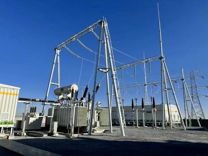
Electricity is rarely used at the same voltage at which it is generated. To transport power efficiently over long distances and safely deliver it to end users, voltage must be adjusted at multiple points across the power grid. This is the vital role of power transformers. Without them, high-voltage transmission would be impractical, losses would surge, and equipment would be damaged by incompatible voltages. Understanding what power transformers are and where they are used is foundational for anyone involved in power engineering, utility operations, or energy infrastructure planning.
Power transformers are high-capacity electrical devices designed to transfer electrical energy between two or more circuits by stepping voltage up or down while maintaining the same frequency. They are primarily used in power generation plants, high-voltage transmission substations, and distribution networks. Their main function is to adjust voltage levels to suit the needs of different stages in the energy delivery process—from generation to final consumption—ensuring efficient, safe, and stable power flow.
They are indispensable components in modern electrical systems and critical for global power infrastructure.
Power transformers are used to step voltage levels up or down in the power grid.True
Their core purpose is to modify voltage for efficient transmission and safe distribution across different parts of the electrical system.
Power transformers are typically found in electronic devices such as laptops and routers.False
Power transformers are industrial-scale units designed for grid-level energy transmission and not used in small electronics.
Power transformers work on the principle of electromagnetic induction and require alternating current (AC) to operate.True
Transformers depend on AC to induce voltage changes between windings using mutual induction.
1. What Is a Power Transformer?
A power transformer is a static electrical device that transfers energy between circuits using electromagnetic induction. Unlike electronic transformers or regulators, power transformers handle high voltages and large currents, typically rated from a few MVA (megavolt-amperes) up to 1500 MVA or more.
Key Characteristics:
| Feature | Description |
|---|---|
| Voltage Range | Typically from 11 kV to 765 kV |
| Power Rating | Ranges from 1 MVA to 1500 MVA |
| Core Material | Silicon steel or amorphous metal |
| Cooling | ONAN, ONAF, OFAF, or OFWF |
| Insulation | Oil-immersed or dry-type |
| Frequency | 50 Hz or 60 Hz depending on country |
Transformers are passive devices with no moving parts (except in tap changers), offering long service life and high efficiency—often above 99.5%.
2. Where Are Power Transformers Used in the Grid?
Power transformers are deployed at several critical points along the generation-to-consumption pathway:
| Grid Location | Transformer Function | Typical Voltage Levels | MVA Range |
|---|---|---|---|
| Generation Station | Step-up transformer (GSU) increases voltage for transmission | 11–26 kV → 220–765 kV | 100–1500 MVA |
| Transmission Substation | Adjust voltage for long-distance or inter-grid transfer | 765/400/220/132 kV | 250–1000 MVA |
| Distribution Substation | Step down for regional and urban distribution | 132 → 33/11/0.4 kV | 2.5–50 MVA |
| Renewable Energy Plants | Step-up from inverter or turbine output to grid-compatible voltage | 0.69–33 → 66–220 kV | 1–200 MVA |
| Industrial Facilities | Deliver suitable voltage for heavy machinery or processes | 66/33/11/6.6 kV | 2–100 MVA |
Infographic: Power Flow and Transformer Location
[Generation Station] → [Step-up Transformer] → [Transmission Line]
→ [Step-down Transformer] → [Distribution Network] → [Consumer]
3. Types of Power Transformers by Application
| Type | Used In | Special Features |
|---|---|---|
| Step-Up Transformer (GSU) | Generation plants | Designed to increase voltage for grid injection |
| Auto-Transformer | Transmission substations | Economical design with shared windings |
| Three-Winding Transformer | Substations with multiple voltage outputs | Reduces need for additional transformer banks |
| Phase-Shifting Transformer | Interconnecting grids | Controls power flow direction and magnitude |
| Inverter-Duty Transformer | Solar and wind farms | Tolerates harmonics, variable loading |
| Dry-Type Transformer | Indoor substations or industrial use | Air-cooled and environmentally safer |
4. How Do Power Transformers Work?
They operate on Faraday’s Law of Electromagnetic Induction, which states:
A changing magnetic field in one coil induces a voltage in another coil.
Components:
| Part | Function |
|---|---|
| Core | Guides magnetic flux efficiently |
| Primary Winding | Connected to input voltage |
| Secondary Winding | Delivers output voltage |
| Insulation | Prevents breakdown between windings |
| Cooling System | Removes heat (oil, fans, radiators) |
| Tank | Contains core, windings, and oil |
Transformer Equation:
$$
frac{V_1}{V_2} = \frac{N_1}{N_2}
$$
Where:
- $V_1$ and $V_2$: Input and output voltages
- $N_1$ and $N_2$: Number of turns in primary and secondary windings
5. Why Are They Essential in the Power Grid?
Power transformers ensure:
- Efficient Transmission: By stepping up voltage, they reduce current and minimize I²R losses
- Safe Distribution: Step-down units allow electricity to be used safely at lower voltages
- Grid Synchronization: Match different voltage and phase requirements between regions
- Flexibility: Support multiple voltage outputs, islanding, and bidirectional flows (esp. with renewables)
- Reliability: Act as protective nodes in case of faults
6. Typical Ratings Across Grid Tiers
| Application | Voltage Ratio (kV) | MVA Range | Cooling |
|---|---|---|---|
| Generation Station | 11/220 or 22/400 | 300–1500 | OFAF / OFWF |
| Transmission Substation | 765/400 or 400/220 | 500–1200 | OFAF |
| Distribution Substation | 132/33 or 33/11 | 2.5–40 | ONAN / ONAF |
| Solar/Wind Plants | 0.69/33 or 33/132 | 1–150 | Dry / Oil-immersed |
What Are Distribution Transformers and Their Applications?
While electricity begins its journey at high-voltage generation plants, it ends in homes, offices, and factories that use much lower voltage. Bridging this voltage gap is the role of distribution transformers—the final step in delivering usable power to consumers. Without them, electricity would remain at dangerously high voltages unsuitable for everyday equipment and appliances. Improper distribution transformer design or application leads to voltage instability, increased losses, and premature equipment failure. That’s why understanding what distribution transformers are and where they are applied is critical for energy planners, utility companies, and industrial users.
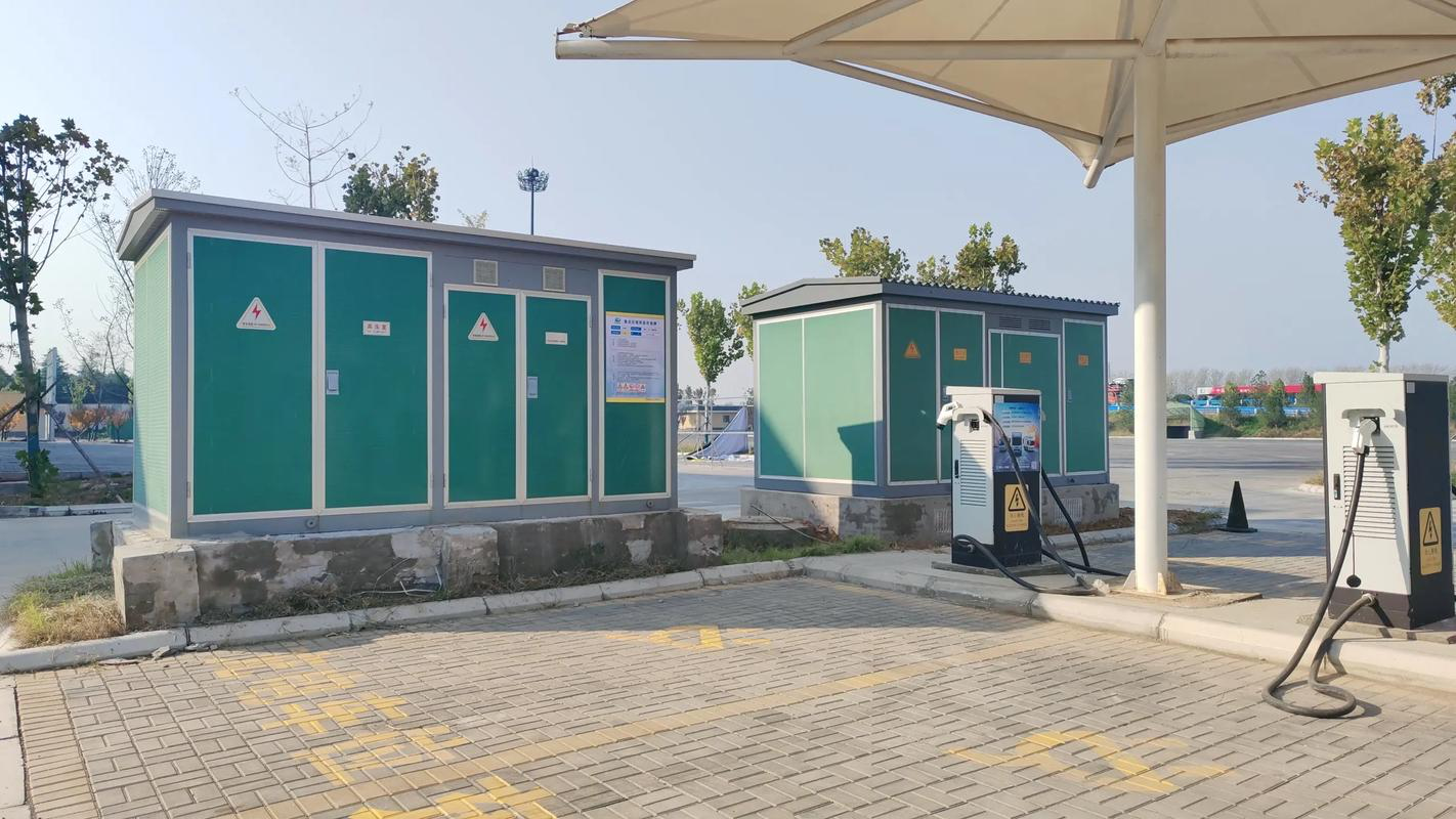
Distribution transformers are static electrical devices that step down medium-voltage electricity (typically 11–33 kV) from the distribution grid to low voltages (400/230 V) suitable for end-user consumption in residential, commercial, or industrial environments. They are commonly found pole-mounted in rural areas or ground-mounted in urban neighborhoods and play a key role in ensuring voltage regulation, safety, and efficient power delivery at the final stage of the electrical grid.
They are essential, ever-present devices that ensure the reliability of modern energy access.
Distribution transformers are used to step down voltage for end-user applications.True
They convert grid-level voltages to low voltages suitable for homes, businesses, and light industry.
Distribution transformers step up voltage for long-distance transmission.False
Step-up functions are handled by power transformers at generation stations; distribution transformers perform step-down operations.
Most power outages in urban areas are related to faults in distribution transformer networks.True
Due to their location close to the load and exposure to weather, distribution transformers are frequent points of failure in urban grids.
1. What Are Distribution Transformers?
A distribution transformer, also known as a service transformer, is the final voltage transformation device in the electric power distribution system. It reduces the voltage of electrical power from medium-voltage (MV) levels—like 33 kV, 22 kV, or 11 kV—to low-voltage (LV) levels such as 415/240 V, usable by households and businesses.
Technical Highlights:
| Attribute | Typical Range |
|---|---|
| Voltage Ratio | 33/0.415 kV, 11/0.415 kV |
| Power Rating | 25 kVA to 2500 kVA |
| Phases | Single-phase or three-phase |
| Cooling | ONAN (Oil Natural Air Natural), dry-type |
| Mounting | Pole-mounted or ground-mounted |
| Insulation | Mineral oil, synthetic oil, or epoxy (for dry type) |
| Efficiency | Up to 99.5%, governed by energy efficiency standards (e.g., DOE, BEE, Ecodesign) |
They are passive, reliable, and designed for long-term use with minimal maintenance.
2. Where Are Distribution Transformers Used?
Distribution transformers are deployed close to end users, typically within urban streets, suburban poles, rural posts, or industrial plants. They are ubiquitous in:
| Sector | Application | Common Voltage |
|---|---|---|
| Residential | Feeding homes and apartment blocks | 11/0.415 kV |
| Commercial | Supplying offices, malls, hospitals | 22/0.415 kV |
| Industrial | Small factories, workshops, warehouses | 33/0.415 or 11/0.415 kV |
| Rural Electrification | Long-distance feeders to villages | 11/0.415 kV |
| Agricultural Use | Pumping and irrigation systems | 11/0.415 kV |
| Underground Networks | Urban load centers with vault or kiosk transformers | 11/0.415 kV dry-type or oil-immersed |
Chart: Voltage Step-Down Path
Transmission Line (132 kV)
→ Substation Transformer (132/33 kV)
→ Distribution Transformer (33/0.415 or 11/0.415 kV)
→ Consumer Load (400/230 V)
3. Types of Distribution Transformers
| Type | Description | Best Use Case |
|---|---|---|
| Pole-Mounted | Compact, oil-immersed, mounted on utility poles | Rural, low-density areas |
| Pad-Mounted | Ground-mounted, tamper-proof enclosure | Suburban and commercial zones |
| Dry-Type | Air-insulated with epoxy resin windings | Indoors or fire-prone areas |
| Underground Vault | Enclosed in sub-surface chambers | Densely populated cities |
| Single-Phase | Used for scattered residential or farm loads | Isolated houses or agriculture |
| Three-Phase | Balanced industrial and commercial loads | City blocks, factories |
Dry-type distribution transformers are suitable for indoor use where fire safety is a concern.True
Their epoxy insulation eliminates oil, reducing fire hazards in enclosed areas like malls, hospitals, and schools.
4. Distribution Transformer Ratings and Standards
| Rating (kVA) | Application | Standard |
|---|---|---|
| 25–100 kVA | Rural single-phase or light commercial | IEC 60076, ANSI C57.12 |
| 160–250 kVA | Urban feeders or apartments | BIS (IS 1180), DOE |
| 315–630 kVA | Shopping centers, substations | BEE Star Rated |
| 1000–2500 kVA | Industrial plants, hospitals, data centers | EU Ecodesign Tier 2 |
Efficiency is critical. For example, EU Ecodesign Tier 2 mandates no-load losses <300 W for a 100 kVA unit, and BIS India provides Star Ratings based on energy performance.
5. Transformer Protection and Accessories
| Component | Purpose |
|---|---|
| Buchholz Relay | Detects internal faults (for oil-filled units) |
| Thermometer | Monitors winding and oil temperature |
| Pressure Relief Valve | Prevents tank rupture |
| Lightning Arresters | Protect against surges |
| Fuses and Circuit Breakers | Line protection |
| Breather Unit | Controls moisture ingress in oil-immersed transformers |
Many modern units include remote monitoring sensors to track oil temperature, voltage imbalances, or overloads.
6. Case Study: 250 kVA Distribution Transformer for a Mixed-Use Development
| Project | Urban residential + commercial complex |
|---|---|
| Transformer | 250 kVA, 11/0.415 kV, ONAN |
| Cooling | Oil-immersed |
| Efficiency | BEE 5-star rated |
| Mounting | Pad-mounted in metal enclosure |
| Accessories | Breather, MOG, surge arresters, fuse box |
| Outcome | Delivered voltage stability within ±5%, reduced energy losses by 18% annually compared to old units |
| Lessons | Energy-efficient distribution transformers significantly reduce operational costs and downtime |
How Do Voltage Levels and Ratings Differ Between Power Transformers and Distribution Transformers?
Electricity travels a complex journey from the point of generation to the point of use, and different types of transformers are used at different stages to ensure efficient and safe voltage management. Power transformers and distribution transformers are the two primary categories in this chain, and while they may appear similar in function, they operate at very different voltage levels and power capacities. Failing to use the correct transformer for a given application can lead to serious operational inefficiencies, grid instability, or catastrophic equipment failure. Understanding how voltage levels and ratings differ between power transformers and distribution transformers is essential for grid planners, utility engineers, and equipment purchasers.
Power transformers typically operate at higher voltage levels ranging from 66 kV to 765 kV and are rated from 100 MVA up to 1500 MVA or more. They are used in generation plants and transmission substations. Distribution transformers, on the other hand, operate at lower voltages, typically 11–33 kV on the primary side and 400/230 V on the secondary side, with ratings from 25 kVA to 2500 kVA. They are installed closer to end users, such as in neighborhoods, commercial zones, and industrial facilities.
These two categories serve distinct roles within the electrical grid hierarchy.
Power transformers operate at higher voltage levels and ratings than distribution transformers.True
Power transformers are used for long-distance transmission and high-capacity loads, while distribution transformers serve local, low-voltage applications.
Distribution transformers are commonly used to step up voltage at power stations.False
Voltage step-up at generation stations is handled by power transformers, not distribution transformers.
Transformer voltage levels and ratings are tailored to their specific grid location and purpose.True
Each transformer type is engineered for its role—generation, transmission, or distribution—and is rated accordingly.
1. Voltage Levels: Power Transformers vs Distribution Transformers
Voltage Range Comparison
| Parameter | Power Transformers | Distribution Transformers |
|---|---|---|
| Primary Voltage | 66 – 765 kV | 11 – 33 kV |
| Secondary Voltage | 132 – 400 kV (step-up/down) | 415/230 V |
| Use Case | Transmission of bulk power over long distances | Final voltage delivery to consumers |
Diagram: Voltage Flow and Transformer Roles
Generation (11–22 kV)
→ [Power Transformer: 22 → 400/765 kV]
→ Transmission Grid
→ [Power Transformer: 400/220 → 132/66 kV]
→ [Distribution Transformer: 33/11 → 0.415/0.230 kV]
→ End Users
Power transformers handle long-distance high-voltage transmission, while distribution transformers manage local low-voltage delivery.
2. Power Ratings and Capacity Differences
| Feature | Power Transformers | Distribution Transformers |
|---|---|---|
| Power Rating | 100 MVA – 1500+ MVA | 25 kVA – 2500 kVA |
| Load Behavior | Operate near full load continuously | Operate at partial load most of the time |
| Typical Installation | Generation plants, transmission substations | Residential blocks, commercial zones, industrial feeders |
| Duty Cycle | Constant, high-efficiency, base load | Intermittent, variable, demand-driven |
Chart: Typical Transformer Ratings by Grid Location
| Location | Voltage (kV) | Rating (MVA or kVA) | Transformer Type |
|---|---|---|---|
| Generation Plant | 22 / 400 | 800–1500 MVA | Power Transformer |
| HV Transmission Substation | 400 / 220 | 500–1000 MVA | Power Transformer |
| Distribution Substation | 33 / 11 | 5–40 MVA | Power Transformer (smaller) |
| Residential Neighborhood | 11 / 0.415 | 25–250 kVA | Distribution Transformer |
| Industrial Site | 33 / 0.415 | 500–2500 kVA | Distribution Transformer |
3. Design Differences Due to Voltage and Rating
| Feature | Power Transformer | Distribution Transformer |
|---|---|---|
| Insulation Level | High (designed for 400+ kV systems) | Medium (for 33/11 kV levels) |
| Cooling System | OFAF, OFWF (forced oil and water cooling) | ONAN, ONAF (natural air/oil cooling) |
| Winding Design | Disc or helical winding with robust insulation | Layered or foil winding, simpler structure |
| Tap Changer | On-load tap changer (OLTC) for voltage regulation | Off-load tap changer or no tap at all |
| Size and Weight | Large, often >100 tons | Compact, from 100 kg to several tons |
| Installation | Grid substations, indoor powerhouses | Outdoor poles, kiosks, or compact enclosures |
4. Efficiency and Regulation Characteristics
| Metric | Power Transformer | Distribution Transformer |
|---|---|---|
| Efficiency at Full Load | 99.5% – 99.7% | 98.5% – 99.5% |
| Loss Emphasis | Load losses critical | No-load losses critical |
| Voltage Regulation | Tight (±1–2%) | More flexible (±5–10%) |
| Energy Efficiency Standards | IEC 60076, DOE 10 CFR 431, CIGRÉ | BEE Star Rating, Ecodesign Tier 2 |
Distribution transformers prioritize low no-load losses because they operate at low utilization for long periods.True
Because distribution transformers often stay energized with light loads, minimizing no-load losses greatly improves efficiency.
5. Application-Specific Use Cases
Power Transformers
- Step-up at Generation Stations: 11/22 kV → 400/765 kV
- Grid-to-grid Interconnection: 400 → 220 kV auto-transformers
- Bulk Transfer Systems: 400 kV lines feeding metro or national load centers
Distribution Transformers
- Urban Power Delivery: 11/0.415 kV transformers serving city blocks
- Rural Electrification: 25–100 kVA pole-mounted units for villages
- Industrial Applications: 33/0.415 kV pad-mounted units in factories
- Commercial Zones: 250–1000 kVA kiosk-type transformers for malls, hotels, hospitals
6. Summary Table: Power vs Distribution Transformers
| Attribute | Power Transformer | Distribution Transformer |
|---|---|---|
| Voltage Level | High (66–765 kV) | Medium/Low (11–0.4 kV) |
| MVA/kVA Rating | 100–1500+ MVA | 25–2500 kVA |
| Application | Generation & Transmission | Distribution to end users |
| Cooling | OFAF, OFWF | ONAN, Dry Type |
| Efficiency Focus | Load losses | No-load losses |
| Tap Changer | OLTC (mandatory) | Off-load or fixed tap |
| Installation Site | Indoor substations, grid hubs | Outdoor poles, kiosks, substations |
What Are the Key Design Differences Between Power and Distribution Transformers?
![]()
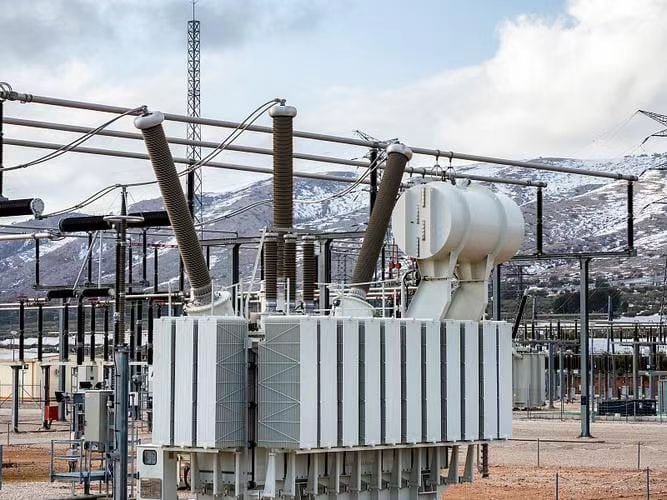
Power and distribution transformers may perform the same fundamental role—voltage transformation—but their internal design, construction, and operating parameters differ significantly due to their placement and purpose in the electrical grid. Improper design selection can lead to higher losses, reduced reliability, or even failure under load or fault conditions. To choose, specify, or engineer the right transformer, it is essential to understand how power and distribution transformers differ in their design characteristics, operational intent, and construction details.
Power transformers are designed for high-voltage, high-capacity transmission applications and prioritize efficiency at or near full load. They feature large core sizes, high-grade insulation, forced cooling systems, and often include advanced tap changers. Distribution transformers are intended for low-voltage delivery to end users, operate under variable loads, and emphasize low no-load losses. They are compact, simpler in structure, and often designed for pole or pad mounting.
These design choices are driven by their distinct grid roles and usage profiles.
Power transformers and distribution transformers have fundamentally different design architectures due to their roles in the grid.True
Design variations such as insulation type, core configuration, cooling methods, and tap changer mechanisms align with different voltage levels and usage patterns.
Power transformers and distribution transformers use the same insulation and cooling technologies regardless of application.False
Cooling and insulation systems are optimized for transformer size, load duty cycle, and voltage class.
Distribution transformers are often designed to minimize no-load losses since they stay energized most of the time without being heavily loaded.True
No-load losses dominate the energy profile of distribution transformers, so designers use thinner laminations and high-quality cores to reduce them.
1. Core Construction and Geometry
| Design Feature | Power Transformer | Distribution Transformer |
|---|---|---|
| Core Type | Typically shell or core-type with larger cross-section | Core-type, compact and optimized for lower flux density |
| Lamination Material | CRGO (Cold Rolled Grain Oriented) or amorphous steel | CRGO, sometimes non-oriented steel in small units |
| Flux Density | Optimized for high efficiency under full load | Lower to limit no-load losses |
| Core Stacking | Step-lap joints for reduced noise and loss | Step-lap or simple mitred core, often more compact |
| Magnetic Circuit Size | Large due to high voltage & MVA rating | Smaller, designed for minimal space and weight |
Infographic: Core Sectional View Comparison
[Power Transformer] → Large, layered shell-type core, vertically stacked limbs
[Distribution Transformer] → Compact core-type with wound limbs and clamp frame
2. Winding Configuration and Insulation
| Parameter | Power Transformer | Distribution Transformer |
|---|---|---|
| Winding Type | Disc, helical, or interleaved for high currents | Layered, spiral, or foil windings |
| Conductor | Copper with high current density | Copper or aluminum (in cost-sensitive models) |
| Insulation System | High-grade paper, pressboard, oil-immersed | Kraft paper, enamel insulation, or epoxy resin (dry) |
| Impulse Withstand | Very high (e.g. 1050–1550 kV BIL for 765 kV) | Moderate (e.g. 95–170 kV BIL for 33/11 kV) |
| Inter-turn Insulation | Reinforced for high surge stress | Standard for low-voltage levels |
| Dielectric Strength | 12–15 kV/mm (oil-immersed, multilayer) | 3–5 kV/mm (dry-type or oil-immersed) |
Table: Insulation Grade Comparison
| Standard | Power Transformer | Distribution Transformer |
|---|---|---|
| IEC 60076-3 | Class A (105°C), B (130°C), F (155°C) | Class B, F, H for dry type |
| Impulse Level | >750 kV for HV side | 75–170 kV (LV side) |
3. Tap Changers and Voltage Regulation
| Attribute | Power Transformer | Distribution Transformer |
|---|---|---|
| Tap Changer Type | On-load tap changer (OLTC), automated | Off-load tap changer or fixed tap |
| Tap Range | ±10–20% with multiple steps | ±2.5–5%, limited steps |
| Voltage Regulation Accuracy | <±1% (continuous under load) | ±5–10% (manual adjustment) |
| Tap Operation Frequency | Continuous, automated via SCADA | Occasional manual operation |
| Location | In-tank or external drive mechanism | Often external or simple manual switchgear |
Power transformers often include on-load tap changers to allow voltage adjustment during operation.True
They need to respond dynamically to transmission voltage fluctuations without service interruption.
4. Cooling System Design
| Feature | Power Transformer | Distribution Transformer |
|---|---|---|
| Cooling Method | OFAF, OFWF, ODAF (forced oil, air, or water) | ONAN, ONAF, or dry-type convection |
| Heat Dissipation Capacity | Very high due to heavy and continuous load | Moderate, built for intermittent loading |
| Radiator Design | Detachable radiators with fans or pumps | Finned tanks or simple tubular design |
| Temperature Monitoring | RTDs, oil thermometers, SCADA-integrated | Bi-metal thermometers or thermal relays |
| Fire Safety | Fire-resistant oil, sealed systems | Dry-type: no oil, safer in indoor applications |
5. Mechanical and Structural Design
| Parameter | Power Transformer | Distribution Transformer |
|---|---|---|
| Weight | 50–300+ tons | 100 kg to several tons |
| Mounting Type | Foundation baseplate, indoor or GIS yard | Pole-mounted, pad-mounted, kiosk-type |
| Tank Design | Pressurized, sealed conservator or nitrogen-sealed | Hermetically sealed or with breather |
| Transport Requirements | Needs multi-axle trailer, cranes | Forklift or bucket-truck portable |
| Accessibility | Designed for regular maintenance | Minimal access; sealed for life in some units |
6. Electrical Performance Parameters
| Characteristic | Power Transformer | Distribution Transformer |
|---|---|---|
| Efficiency | Peak at or near full load (>99.5%) | Peak at light load (98.5–99.2%) |
| No-load Losses | Secondary concern | Primary concern (dominant in idle state) |
| Load Losses | Minimized through conductor size, winding design | Lower due to small size and low duty |
| Thermal Class | Higher temperature tolerance | Designed for ambient use |
| Sound Level | Noise-controlled via damping and core tuning | Limited noise emission by size/design |
Summary Table: Key Design Differences
| Design Element | Power Transformer | Distribution Transformer |
|---|---|---|
| Voltage Levels | 66–765 kV | 11–0.415 kV |
| Ratings | 100–1500+ MVA | 25–2500 kVA |
| Cooling | OFAF / OFWF | ONAN / Dry-type |
| Tap Changer | OLTC (automated) | Off-load or fixed tap |
| Core Size | Large and efficient | Compact and cost-effective |
| Mounting | Substation or indoor plant | Pole/pad-mounted or kiosk |
| Efficiency Focus | Full-load optimization | No-load loss minimization |
How Do Their Efficiency and Load Profiles Compare?
Selecting the right transformer for a specific application is not only about voltage and capacity—it's about how the transformer performs across varying load conditions and how efficiently it converts electrical energy. While both power and distribution transformers aim to minimize energy loss, they are designed for very different load profiles and efficiency priorities. Failing to match a transformer to its expected load cycle can lead to high losses, poor voltage regulation, and excessive operating costs. Therefore, understanding how their efficiency and load profiles compare is critical for utilities, engineers, and plant managers striving for reliability and cost-effectiveness.
Power transformers are optimized for high efficiency at or near full-load operation and typically operate with a high and steady load factor (above 70%). They exhibit low load losses and are designed for continuous-duty performance. In contrast, distribution transformers often operate under fluctuating or light-load conditions (average 20–50% load factor) and are optimized to reduce no-load losses, which dominate their energy profile due to 24/7 energization. Efficiency peaks at partial loads, and design choices prioritize idle-state energy savings.
This distinction stems from their grid location and usage behavior.
Power transformers are designed for peak efficiency at full load, while distribution transformers are optimized for partial load efficiency.True
Power transformers run near capacity continuously, whereas distribution transformers experience low and variable loads, requiring different efficiency optimization.
Distribution transformers are more efficient than power transformers under all conditions.False
Distribution transformers are efficient at partial loads, but power transformers outperform them at high, constant loads due to their design.
Load losses dominate the total losses in power transformers, while no-load losses are more significant in distribution transformers.True
This is due to their operating profiles—power transformers are mostly loaded, while distribution transformers stay energized regardless of load.
1. Efficiency Profile Comparison
Graph: Efficiency vs. Load Curve
| Load Level (% of Rated) | Power Transformer Efficiency | Distribution Transformer Efficiency |
|---|---|---|
| 25% | ~97.5% | ~98.5% (peak) |
| 50% | ~98.8% | ~98.3% |
| 75% | ~99.4% | ~98.0% |
| 100% | ~99.6% (peak) | ~97.5% |
- Power Transformer Peak Efficiency: Occurs at 75–100% load
- Distribution Transformer Peak Efficiency: Occurs at 30–50% load
Insight:
Distribution transformers lose efficiency when heavily loaded, while power transformers become less efficient at light loads.
2. Loss Components Comparison
| Loss Type | Power Transformer | Distribution Transformer |
|---|---|---|
| Core (No-load) Losses | Lower percentage (~10–20%) | Higher percentage (~40–70%) |
| Copper (Load) Losses | Dominant at full load (~80%) | Lower, as unit operates underloaded |
| Stray Losses | Considered in detailed design | Typically minimal |
| Cooling Losses | Present in large units (fans, pumps) | Negligible or passive cooling |
Chart: Loss Distribution by Load
Power Transformer:
  - 20% No-load Losses
  - 75% Load Losses
  - 5% Cooling Losses

Distribution Transformer:
  - 60% No-load Losses
  - 35% Load Losses
  - 5% Miscellaneous
Power transformers experience most of their energy loss under load conditions, while distribution transformers waste more energy even at low or no load.True
Power transformers are used continuously at high load, whereas distribution transformers remain energized 24/7 regardless of demand.
3. Load Profile and Utilization Factor
| Characteristic | Power Transformer | Distribution Transformer |
|---|---|---|
| Typical Load Factor | 70% – 95% | 20% – 60% |
| Load Curve Shape | Flat or base-loaded | Variable, often peaking in morning/evening |
| Operating Hours | Constant | Continuous, but load varies |
| Idle Time | Minimal | Long periods with low or no load |
| Design Priority | Minimize copper (load) losses | Minimize iron (core) losses |
Example: 24-Hour Load Behavior
Power Transformer:  Constant 80% Load
Distribution Transformer:  Varies from 10% (night) to 60% (peak)
4. Energy Efficiency Regulations and Benchmarks
| Standard | Coverage | Efficiency Focus |
|---|---|---|
| IEC 60076-1 | General transformers | Performance measurement |
| IEC 60076-20 | Energy efficiency for large power transformers | Load loss optimization |
| DOE 10 CFR 431 | U.S. commercial transformers | Total loss caps (based on kVA) |
| EU Ecodesign Tier 2 | Distribution transformers | Stringent no-load and load loss limits |
| BEE Star Rating (India) | Distribution transformers | Star-rated based on losses |
Example Limits (100 kVA, 11/0.415 kV):
| Star Rating | No-load Loss (W) | Load Loss (W) |
|---|---|---|
| 3-Star | ≤ 260 | ≤ 1550 |
| 5-Star | ≤ 210 | ≤ 1340 |
5. Cooling and Thermal Behavior
| Parameter | Power Transformer | Distribution Transformer |
|---|---|---|
| Cooling Type | OFAF, OFWF, ODAF | ONAN, Dry |
| Temperature Rise Limits | +55°C to +65°C | +40°C to +55°C |
| Load Impact on Temp | Proportional | Varies with ambient |
| Heat Dissipation Priority | Critical for constant high load | Secondary, due to low duty cycle |
6. Real-World Use Case Comparison
| Use Case | Power Transformer | Distribution Transformer |
|---|---|---|
| Utility Transmission Substation | 500 MVA, 400/220 kV | Not applicable |
| Industrial Plant | 2500 kVA, 33/0.415 kV | Common application |
| Urban Grid | Supplies 100 MVA over 5 units | Multiple 100–315 kVA units |
| Smart Grid Integration | Includes OLTC, digital diagnostics | Includes smart meters, remote monitoring |
| Energy Savings Target | Reduce copper and eddy losses | Reduce core and stray losses |
What Are the Cost and Maintenance Considerations Between Power and Distribution Transformers?
Whether designing a new electrical system or upgrading existing infrastructure, one of the most critical decisions is choosing the right transformer—not only in terms of voltage and rating but also from a lifecycle cost and maintenance perspective. Both power transformers and distribution transformers require investment and upkeep, but they differ substantially in upfront costs, maintenance demands, operational risks, and long-term performance requirements. Ignoring these factors can lead to cost overruns, unplanned outages, or premature equipment failure. So what are the cost and maintenance considerations that differentiate these two essential transformer classes?
Power transformers demand higher capital investment, intensive monitoring, and scheduled preventive maintenance due to their large capacity (typically 100 MVA to 1500 MVA), high voltage levels, and mission-critical roles in transmission networks. In contrast, distribution transformers (25 kVA to 2500 kVA) have lower initial costs, minimal maintenance requirements, and often feature sealed or ‘maintenance-free’ designs. However, due to their widespread deployment and continuous energization, even minor maintenance issues can multiply into significant system-wide costs if neglected.
Understanding these financial and technical trade-offs is essential for effective asset planning.
Power transformers are more expensive to purchase, install, and maintain than distribution transformers.True
Due to their size, complexity, voltage class, and grid criticality, power transformers incur higher lifecycle costs.
Distribution transformers usually require complex maintenance routines similar to power transformers.False
Most distribution transformers are designed for minimal maintenance, often with sealed construction for outdoor use.
Regular oil testing and diagnostic monitoring are critical for power transformer reliability.True
Because of the high cost and critical function of power transformers, early fault detection through oil analysis is essential.
1. Capital and Installation Cost Comparison
| Feature | Power Transformer | Distribution Transformer |
|---|---|---|
| Typical Rating | 100 – 1500+ MVA | 25 – 2500 kVA |
| Voltage Class | 132 – 765 kV | 11 – 33 kV |
| Base Unit Cost | $100,000 – $3 million+ | $1,000 – $25,000 |
| Installation Cost | $50,000 – $500,000 (civil, HV yard, crane) | $500 – $5,000 (pole or pad mount) |
| Delivery Lead Time | 8 – 18 months | 4 – 12 weeks |
| Engineering & Testing | Extensive FAT/SAT, custom specs | Standardized designs, minimal customization |
Chart: Comparative Capital Cost Range
| Transformer Type | Rating | Approximate Cost |
|---|---|---|
| Power Transformer | 250 MVA, 220/66 kV | $750,000–$1.5 million |
| Distribution Transformer | 250 kVA, 11/0.415 kV | $3,000–$5,000 |
Installation of power transformers also involves site preparation, gantries, oil containment pits, and sometimes gas-insulated substations (GIS), increasing costs further.
2. Operation and Maintenance (O\&M) Requirements
| Maintenance Task | Power Transformer | Distribution Transformer |
|---|---|---|
| Oil Sampling & DGA | Quarterly to annually | Every 2–5 years or never (if sealed) |
| Bushing Inspection | Regular thermography | Minimal or fixed-type bushings |
| OLTC Service | Every 20,000–50,000 operations | Not applicable in most cases |
| Cooling System Check | Monthly or continuous | Basic visual inspection |
| Breather Maintenance | Replace silica gel every 6–12 months | Only if equipped (many are sealed units) |
| Insulation Resistance Testing | Annually | Every 2–3 years |
| Online Monitoring | SCADA, IoT, thermal sensors | Optional for smart grids |
Maintenance Frequency Table
| Task | Power Transformer | Distribution Transformer |
|---|---|---|
| Oil DGA | 3–4x per year | Rare or during overhaul |
| Thermography | Monthly | Seasonal or reactive |
| OLTC Tuning | Automated, online | Not present |
| Visual Inspection | Weekly to monthly | Every 6–12 months |
| Cleaning & Bushings | Semiannual | Annual or when faulty |
3. Lifecycle Cost and TCO (Total Cost of Ownership)
| Parameter | Power Transformer | Distribution Transformer |
|---|---|---|
| Service Life | 30–50 years (with refurbishment) | 15–30 years |
| Preventive Maintenance Cost | $10,000 – $100,000/year | $50 – $1,000/year/unit |
| Failure Cost Risk | High (grid outage, equipment loss) | Moderate (localized outage) |
| Monitoring Equipment Cost | High (IoT, SFRA, temperature sensors) | Optional or basic smart meter |
| Downtime Impact | Network-wide | End-user localized |
| Typical TCO (30 years) | $2M – $8M+ | $5,000 – $50,000 |
Pie Chart: Lifecycle Cost Breakdown (%)
| Cost Component | Power Transformer | Distribution Transformer |
|---|---|---|
| CapEx | 45% | 65% |
| Maintenance | 25% | 10% |
| Downtime Risk | 15% | 5% |
| Energy Losses | 10% | 15% |
| Disposal/Replacement | 5% | 5% |
4. Reliability and Risk Management
| Risk Factor | Power Transformer | Distribution Transformer |
|---|---|---|
| Oil Degradation | Must be monitored (DBDS, furan, moisture) | Minor risk in sealed units |
| Thermal Overload | Significant at high MVA | Rare unless overloaded |
| Fault Detection | Online DGA, SFRA, bushing monitoring | Fuse trip or thermography |
| Failure Impact | Blackout across substations or regions | Local service disruption |
| Replacement Time | 8–12 months | 2–4 weeks |
| Spare Availability | Strategic spares often required | Stocked in utility stores |
5. Smart Monitoring Trends and Digitalization
| Technology | Power Transformer | Distribution Transformer |
|---|---|---|
| IoT Sensors | Yes, common in new designs | Emerging in modern grids |
| SCADA Integration | Mandatory in T\&D networks | Optional |
| Predictive Maintenance | AI-based models from sensor data | Basic analytics or alert thresholds |
| Load and Thermal Monitoring | Continuous | Optional |
| Remote Diagnostics | Yes (RTU, modbus, GSM) | Limited or new tech-enabled only |
Power transformers are more likely to be fitted with smart monitoring systems for predictive maintenance.True
Due to their critical role, utilities invest in digital diagnostics and online fault prediction for power transformers.
6. Maintenance Cost vs Energy Loss Trade-off
In distribution transformers, no-load losses contribute significantly to total energy cost. Choosing higher efficiency (e.g., BEE 5-Star or EU Tier 2) models reduces recurring electricity loss, which can outweigh maintenance expenses.
Example: 100 kVA, 11/0.415 kV
| Star Rating | No-load Loss | Annual Energy Cost (at $0.10/kWh) |
|---|---|---|
| 3-Star | 300 W | ~$262.80 |
| 5-Star | 210 W | ~$183.96 |
| Annual Savings | — | $78.84 per unit |
In large utility fleets, cumulative savings from low-loss distribution transformers can reach millions.
Conclusion
While power transformers and distribution transformers may appear similar in structure, they serve fundamentally different purposes in the grid. Power transformers operate at high voltage and are designed for maximum efficiency during full-load conditions, making them ideal for transmission systems. In contrast, distribution transformers work closer to the end user, stepping down voltage to usable levels and operating efficiently under variable, lower loads. Understanding these distinctions is crucial for engineers, utilities, and procurement teams involved in power system design and operation.
FAQ
Q1: What is the primary difference between a power transformer and a distribution transformer?
A1: Power transformers are used in transmission networks for high voltage applications (typically above 33 kV), to step up or step down voltages over long distances.
Distribution transformers are used in distribution networks, stepping down voltage to usable levels (typically <33 kV) for residential, commercial, and industrial consumers.
Q2: Where are power and distribution transformers used?
A2: Power transformers: Generation substations, transmission grids, and interconnection points
Distribution transformers: Pole-mounted or ground-mounted units in local neighborhoods, near end-users
Power transformers handle bulk power transfer, while distribution transformers deliver power to the end-user.
Q3: How do their load characteristics differ?
A3: Power transformers operate near full load capacity most of the time for high efficiency.
Distribution transformers operate under variable load conditions, with peak usage during certain periods.
Distribution transformers are designed for maximum efficiency at 50-70% load, unlike power transformers.
Q4: What are the differences in size and design?
A4: Power transformers are larger, with robust cooling systems (e.g., OFAF, ONAN) and high voltage insulation
Distribution transformers are smaller, with simpler cooling systems and easier installation
Also, power transformers often have on-load tap changers, while distribution transformers usually use off-circuit tap changers.
Q5: Are there differences in efficiency and cost?
A5: Power transformers offer higher efficiency and are optimized for minimum load loss over continuous operation
Distribution transformers prioritize cost-effectiveness, compactness, and moderate efficiency for variable loads
Overall, power transformers are more expensive and critical for grid-level voltage regulation.
References
Electrical4U: Power vs Distribution Transformers
https://www.electrical4u.com/difference-between-power-transformer-and-distribution-transformer/
IEEE: C57 Transformer Standards
https://standards.ieee.org/ieee/c57/
NREL: Grid Transformer Classifications
https://www.nrel.gov/docs/fy20osti/transformer-grid.pdf
ScienceDirect: Analysis of Transformer Types and Use
https://www.sciencedirect.com/science/article/abs/pii/S1364032118303867
