Calculating transformer load is essential to ensure it operates within its rated capacity, preventing overheating, reduced lifespan, and unexpected failures. The load calculation considers voltage, current, and power factor to determine how much electrical demand the transformer is carrying at any given time. This process helps engineers, operators, and maintenance teams optimize performance and plan for system expansion.
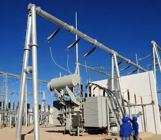
What Are the Basics of Transformer Load and How Do They Affect Performance?
![]()
Overloading a transformer or failing to match its load rating to the system demand can cause excessive heating, accelerated insulation breakdown, voltage drops, and reduced lifespan. Many premature transformer failures occur because users do not fully understand how load affects efficiency, temperature rise, and performance under varying operating conditions. Without proper load management, maintenance costs rise and reliability drops.
Transformer load refers to the amount of electrical power (in kVA or MVA) drawn from the transformer relative to its rated capacity. It determines current flow in the windings, heating in both copper and core, and directly impacts efficiency, voltage regulation, and service life.
Understanding transformer load principles is essential because operating too close to maximum capacity for prolonged periods can significantly shorten insulation life, while consistently underloading a transformer can lead to poor efficiency and wasted investment.
A transformer can be continuously operated at 120% of its rated load without damage.False
Continuous operation above the nameplate kVA rating increases winding temperature beyond design limits, reducing insulation life and potentially causing failure. Overloads should be within short-duration limits defined by standards.
1. Key Concepts in Transformer Loading
- Rated Load: The maximum continuous load a transformer can carry at its rated temperature rise without exceeding insulation class limits.
- Load Factor: Ratio of average load to maximum possible load over a given period — important for thermal modeling.
- Peak Load: Short-term high demand periods; transformers can tolerate them if within short-duration overload limits.
- Diversity Factor: Helps size transformers based on expected simultaneous demand from multiple loads.
2. Load-Related Losses
| Loss Type | Depends On | Description |
|---|---|---|
| No-load loss | Voltage | Constant core losses (hysteresis + eddy currents) independent of load. |
| Load loss | Current² | Copper (I²R) losses and stray load losses that increase with load. |
3. Load Profiles and Impact on Life Expectancy
| Load Profile | Typical Application | Effect on Transformer |
|---|---|---|
| Constant Load | Industrial plant main feeder | Predictable heating, easier design life estimates |
| Cyclical Load | HVAC systems, pumps | Repeated heating/cooling cycles can cause thermal fatigue |
| Intermittent Peaks | Data centers during failover | Short bursts acceptable if within emergency rating |
| Light Load | Backup/emergency transformers | Low efficiency, higher relative no-load loss |
4. Temperature Rise and Loading Relationship
Transformer winding temperature rise is proportional to approximately the 1.6 power of load current. For example:
text{Temp Rise Ratio} \approx \left(\frac{I{load}}{I{rated}}\right)^{1.6}
This means even small overloads cause disproportionately high temperature increases.
5. Best Practices for Load Management
- Keep average load factor between 50–80% for optimal efficiency and lifespan.
- Use demand monitoring systems to detect trends and prevent chronic overloading.
- Plan for future load growth by selecting capacity with margin but avoiding excessive oversizing.
- Coordinate transformer impedance with protection settings to ensure safe fault clearing.
6. Example Calculation — Load Factor
If a 2000 kVA transformer has an average daily load of 1300 kVA:
text{Load Factor} = \frac{1300}{2000} = 0.65 \; (65\%)
A 65% load factor is generally good for balancing efficiency and longevity.
What Is the Formula for Transformer Load Calculation and How Is It Applied?
Incorrect load calculation can result in oversizing (wasting investment) or undersizing (overheating and premature failure) of transformers. Many field issues stem from engineers or technicians applying only approximate rules instead of precise electrical formulas, leading to unreliable power delivery.
The basic formula for transformer load in kVA is:
For single-phase:
text{kVA} = \frac{V \times I}{1000}
For three-phase:
text{kVA} = \frac{\sqrt{3} \times V \times I}{1000}
where:
- $V$ = voltage in volts
- $I$ = current in amperes
- $sqrt{3}$ ≈ 1.732 for three-phase power systems
Transformer load in kVA is calculated the same way for single-phase and three-phase systems.False
Three-phase load calculation requires multiplying by √3 due to the vector relationship between phase voltages and currents.
1. Formula Breakdown
| Parameter | Unit | Description |
|---|---|---|
| Voltage $V$ | Volts (V) | RMS value of primary or secondary voltage |
| Current $I$ | Amperes (A) | RMS load current |
| √3 factor | – | Present only in three-phase systems to account for vector sum of power in each phase |
| 1000 divisor | – | Converts from VA to kVA |
2. Example Calculations
Single-Phase Example:
A transformer secondary supplies 240 V at 150 A:
\text{kVA} = \frac{240 \times 150}{1000} = 36\ \text{kVA}
Three-Phase Example:
A transformer secondary supplies 400 V at 200 A:
\text{kVA} = \frac{1.732 \times 400 \times 200}{1000} \approx 138.56\ \text{kVA}
3. Determining Load Percentage
Once kVA is calculated, compare it with the transformer’s nameplate rating to find the load percentage:
\text{Load \%} = \frac{\text{kVA}{\text{measured}}}{\text{kVA}{\text{rated}}} \times 100
Example:
If a 150 kVA transformer is loaded at 138.56 kVA:
\text{Load \%} = \frac{138.56}{150} \times 100 \approx 92.37\%
4. Practical Considerations
- Always use RMS values from instruments for accuracy.
- For split-phase residential systems, treat each leg as single-phase unless specified.
- Current imbalance between phases in a three-phase transformer should be kept minimal to avoid uneven heating.
- In renewable systems, account for harmonic currents when calculating load, as they increase effective current without adding useful power.
How Do You Assess Actual vs. Rated Load in a Transformer?
Operating a transformer without knowing whether its actual load exceeds the rated load is like driving a truck without checking its cargo weight—it may work for a while, but stress and overheating will shorten its life. Excess load leads to insulation breakdown, higher losses, and possible catastrophic failure. Under-loading, on the other hand, wastes investment and reduces efficiency in certain cases.
To assess actual vs. rated load, measure the operating voltage and current, calculate the actual kVA using the correct single-phase or three-phase formula, and compare it to the transformer’s nameplate rating to find the load percentage.
A transformer can be continuously operated at 110% of its rated load without any risk.False
Continuous operation above the rated load accelerates insulation aging and increases the risk of overheating, even if short-term overloading is sometimes permissible.
1. Steps for Load Assessment
| Step | Action | Tools Needed |
|---|---|---|
| 1 | Locate nameplate kVA rating, voltage, and phase | Visual inspection |
| 2 | Measure operating voltage (V) and current (A) on each phase | Clamp meter, multimeter, or power analyzer |
| 3 | Calculate actual load in kVA using the correct formula | Calculator or spreadsheet |
| 4 | Compute load percentage = (Actual kVA / Rated kVA) × 100 | Same as above |
| 5 | Record readings for trend analysis | Maintenance log or monitoring system |
2. Calculation Example
Transformer Nameplate:
- Rated: 500 kVA, 3-phase
- Rated Voltage: 400 V
Measured:
- Voltage: 398 V
- Current: 650 A
Actual Load (3-phase):
\text{kVA}_{\text{actual}} = \frac{1.732 \times 398 \times 650}{1000} \approx 447.4\ \text{kVA}
Load Percentage:
\text{Load \%} = \frac{447.4}{500} \times 100 \approx 89.48\%
3. Best Practices in Assessing Load
- Measure during peak demand to capture worst-case loading.
- Check for phase imbalance by comparing current readings per phase.
- Log values over time to spot trends or seasonal variations.
- Consider harmonics measurement if feeding nonlinear loads—distorted currents can overheat the transformer even at “normal” kVA.
- Install permanent load monitors in critical facilities for real-time assessment.
4. Decision Guidance
- Below 80%: Ample capacity, low thermal stress.
- 80–100%: Acceptable but close to maximum—monitor regularly.
- >100%: Overload condition—reduce load or upgrade transformer.
How Do You Monitor and Manage Transformer Load Over Time?
Ignoring transformer load trends is like driving a car by only glancing at the speedometer once a month—you miss the warning signs. Transformers may survive occasional peaks, but sustained overload, seasonal demand changes, or hidden load growth will slowly degrade insulation and shorten lifespan. Without ongoing monitoring, these risks go unnoticed until costly failures occur.
The most effective way to manage transformer load over time is to implement continuous or periodic load monitoring, record key parameters (kVA, current, voltage, temperature), analyze historical trends, and adjust system operation or capacity before ratings are exceeded.
Transformer load can be accurately assessed with a single measurement taken at any time of day.False
Transformer load varies throughout the day and seasons, so multiple or continuous measurements are needed to understand true operating conditions.
1. Monitoring Strategies
| Method | Description | Pros | Cons |
|---|---|---|---|
| Spot Measurement | Manual readings during peak or random times | Low cost, simple | Misses load variations, limited insight |
| Periodic Logging | Scheduled manual readings (daily/weekly) | Better trend capture | Labor-intensive, possible gaps |
| Continuous Monitoring | Real-time sensors with data logging | Full visibility, alarms possible | Higher upfront cost |
| Smart Grid Integration | Automatic reporting to utility control center | Enables predictive management | Requires compatible infrastructure |
2. Key Parameters to Track
- kVA load (calculated from voltage & current)
- Phase currents (detect imbalance)
- Voltage stability (prevent over/under-voltage stress)
- Top-oil and winding temperatures (thermal health)
- Harmonic distortion (THD) for nonlinear loads
3. Example: Trend Analysis Table
| Month | Avg Load (kVA) | Peak Load (kVA) | Peak Temp (°C) | Load % of Rated |
|---|---|---|---|---|
| Jan | 420 | 480 | 65 | 84% |
| Apr | 450 | 505 | 68 | 88% |
| Jul | 480 | 550 | 75 | 94% |
| Oct | 430 | 470 | 66 | 86% |
From this trend, the transformer is approaching critical load in summer—a sign to consider load redistribution or capacity upgrades before the next hot season.
4. Managing Load Over Time
- Load Balancing: Distribute loads evenly across phases and transformers.
- Peak Shaving: Use on-site generation or battery storage during peak hours.
- Preventive Maintenance: Schedule inspections when load is lower to avoid downtime.
- Capacity Planning: Use historical data to justify upgrades or new transformer installations.
5. Proactive Actions from Monitoring Data
- Identify seasonal or time-of-day peaks.
- Detect creeping load growth before overloads occur.
- Predict end-of-life based on thermal aging models.
- Improve energy efficiency by operating closer to optimal load range (usually 40–80%).
Conclusion
Transformer load calculation is a straightforward but crucial process that ensures safe and efficient operation. By applying the correct formulas and regularly monitoring load levels, operators can prevent overloading, reduce maintenance costs, and extend transformer service life. Proper load management not only safeguards the transformer but also improves overall power system reliability.
FAQ
Q1: What is transformer load?
Transformer load refers to the amount of electrical demand placed on a transformer at a given time. It is typically measured in kilovolt-amperes (kVA) or megavolt-amperes (MVA) and reflects the total power the transformer is supplying to connected equipment.
Q2: How is transformer load calculated?
Transformer load is calculated using the formula:
Single-phase: kVA = (Volts × Amps) / 1,000
Three-phase: kVA = (Volts × Amps × √3) / 1,000
You need to know the transformer’s operating voltage and the current drawn by the connected load to determine its load accurately.
Q3: Why is load calculation important for transformers?
Accurate load calculation ensures the transformer operates within its rated capacity, avoiding overheating, energy loss, and premature failure. It also helps in selecting the correct transformer size for both existing and future load requirements.
Q4: How can I determine if my transformer is overloaded?
A transformer is overloaded when its load exceeds its rated kVA capacity. Signs include excessive heat, reduced voltage output, tripped protection devices, and increased energy losses. Continuous monitoring of current and voltage helps detect overload conditions early.
Q5: What factors affect transformer load capacity?
Factors include ambient temperature, cooling method, load type (continuous or intermittent), power factor, and harmonics in the electrical system. Poor power factor and harmonic distortion can reduce effective load capacity, even if the kVA rating is not exceeded.
References
IEEE - Transformer Loading Guide: https://ieeexplore.ieee.org
NEMA - Transformer Application Information: https://www.nema.org
Electrical4U - Transformer Load Calculation: https://www.electrical4u.com
EEP - How to Calculate Transformer Load: https://electrical-engineering-portal.com
Energy.gov - Transformer Performance Standards: https://www.energy.gov
All About Circuits - Transformer Load Basics: https://www.allaboutcircuits.com
Engineering Toolbox - Transformer Load Charts: https://www.engineeringtoolbox.com