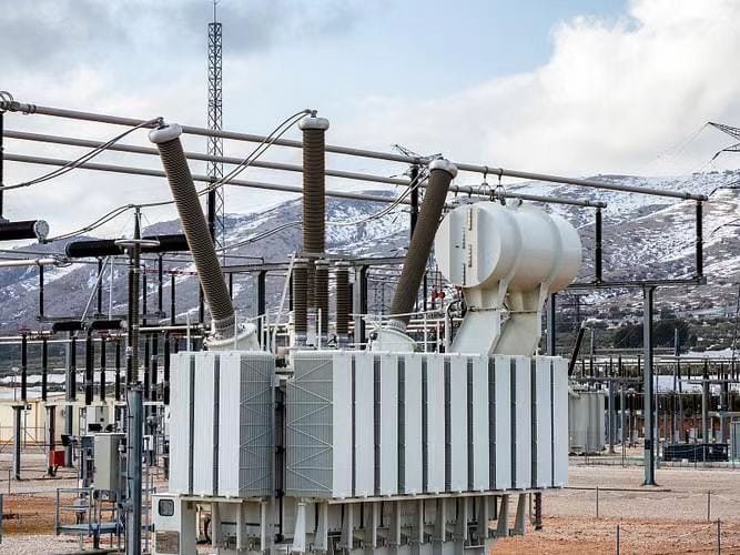
Grounding and protection are essential aspects of power transformer design, installation, and operation. Proper grounding ensures safety, minimizes electrical hazards, and enhances system stability, while protection mechanisms safeguard transformers against faults, overloads, and external disturbances. Following best practices not only extends the service life of transformers but also prevents costly downtime and damage.
Why Is Proper Grounding Essential for Power Transformers?
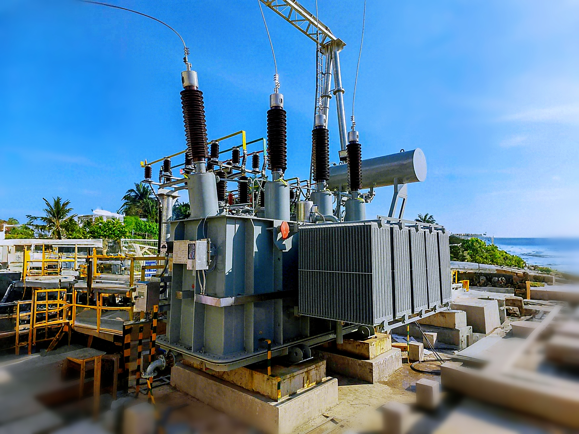
One of the most overlooked yet critical issues in transformer operation is improper grounding. Without correct grounding, transformers face the risks of fault currents, insulation failure, dangerous touch voltages, equipment damage, and safety hazards to personnel. A poorly grounded system can lead to frequent tripping, overvoltages, and catastrophic failures that shorten transformer lifespan. The solution lies in designing and maintaining a robust grounding system that ensures safety, system stability, and compliance with international standards.
Proper grounding of power transformers is essential to provide a safe path for fault currents, stabilize system voltage, protect equipment insulation, and safeguard personnel. Grounding connects transformer neutrals, tanks, and metallic parts to earth, preventing dangerous overvoltages during lightning strikes, switching surges, or short circuits. Without proper grounding, transformers are exposed to increased failure rates, unstable operation, and severe safety risks.
When done correctly, grounding not only enhances transformer reliability and efficiency but also ensures compliance with IEC, IEEE, and national safety codes.
Grounding a transformer is optional if the system has protective relays installed.False
Grounding is mandatory regardless of protective relays; it ensures safe fault current dissipation and stabilizes voltage.
Grounding a transformer neutral prevents overvoltages caused by lightning and switching surges.True
Neutral grounding provides a low-impedance path to earth, protecting insulation and equipment.
1. Functions of Proper Transformer Grounding
a) Safety Protection
- Provides a low-resistance path for fault currents to flow to earth.
- Prevents hazardous step and touch voltages.
- Protects operating staff during abnormal events.
b) System Stability
- Stabilizes system voltage during unbalanced load conditions.
- Controls transient overvoltages caused by switching or lightning.
c) Equipment Protection
- Limits insulation stress on windings and bushings.
- Prevents damage to transformer tanks and metallic parts.
- Minimizes the risk of fire and catastrophic failures.
2. Grounding Methods for Power Transformers
| Grounding Method | Application | Advantages | Limitations |
|---|---|---|---|
| Solid Grounding | LV and MV distribution | Simple, effective fault clearance | High fault current magnitude |
| Resistance Grounding | HV/MV networks | Limits fault current, reduces damage | Adds cost, requires resistor banks |
| Reactance Grounding | EHV systems | Controls transient overvoltages | May create resonance issues |
| Ungrounded (rare today) | Industrial isolated systems | Maintains continuity during first fault | Risk of overvoltages, unsafe for modern grids |
3. Transformer Grounding Components
- Neutral Grounding: Connects transformer star-point to earth through a resistor/reactor or directly.
- Tank and Core Grounding: Ensures transformer body and metallic enclosures are bonded to earth.
- Lightning Arrester Grounding: Provides surge protection by discharging overvoltages safely to earth.
- Grounding Grid: Buried copper conductors ensuring safe dissipation of current across soil.
4. Standards and Compliance
- IEC 60076-3 & IEC 61936: Specify grounding requirements for transformer installations.
- IEEE Std 80 & C57.12: Provide guidelines for neutral grounding and safe step/touch voltage limits.
- National Codes (NEC, IS, etc.): Enforce safe grounding practices at the utility and industrial levels.
5. Case Study Example
In 2020, a 220 kV transformer failure in Southeast Asia was traced back to an improperly bonded grounding grid. The fault current did not fully dissipate, resulting in bushing flashover, tank rupture, and complete transformer loss. A properly engineered ground grid with resistance-limited neutral grounding would have prevented the incident, saving millions in equipment and downtime.
6. Technical Considerations in Grounding Design
- Soil Resistivity: Determines grounding grid size and depth.
- Fault Current Magnitude: Guides the choice between solid, resistance, or reactance grounding.
- Step & Touch Voltage Analysis: Ensures compliance with IEEE 80 safety limits.
- Maintenance: Periodic testing of ground resistance ensures long-term reliability.
What Are the Common Grounding Methods Used in Power Transformers?
One of the main challenges engineers face when installing power transformers is deciding on the right grounding method. Improper or mismatched grounding not only exposes transformers to fault damage and insulation breakdown but also creates serious safety risks for personnel. Grounding determines how fault currents are handled, how system voltage remains stable during unbalanced conditions, and how effectively overvoltages are dissipated. Without the correct grounding method, transformers can experience dangerous overvoltages, excessive heating, or even catastrophic failure. The solution is to adopt the most appropriate grounding scheme according to system design, voltage level, and fault current considerations.
The most common grounding methods used in power transformers are solid grounding, resistance grounding, reactance grounding, and isolated (ungrounded) systems. Solid grounding provides a direct earth connection, resistance grounding limits fault current using a resistor, reactance grounding uses an inductor to control fault current and transients, and isolated systems leave the neutral ungrounded. Each method has distinct advantages and applications: solid grounding is common in LV/MV systems, resistance grounding in HV networks, reactance grounding in EHV grids, while ungrounded systems are rare and used mainly in specific industrial processes.
For customers, knowing the right grounding method ensures higher safety, longer transformer life, and compliance with IEC/IEEE standards.
All power transformers must be solidly grounded regardless of application.False
Solid grounding is not universal; resistance and reactance grounding are widely used to limit fault current in HV/EHV systems.
Resistance grounding helps reduce damage during line-to-ground faults by limiting current.True
By inserting a neutral grounding resistor, fault current is limited, reducing stress on insulation and windings.
1. Solid Grounding
- Description: Transformer neutral is directly connected to earth.
- Applications: Low and medium voltage (LV/MV) distribution networks.
- Advantages: Simple, ensures quick fault clearance, improves system stability.
- Limitations: Produces high fault currents, requiring strong switchgear and protective relays.
2. Resistance Grounding
- Description: A resistor is connected between transformer neutral and earth.
Types:
- Low-Resistance Grounding (LRG): Allows higher fault current for selective tripping.
- High-Resistance Grounding (HRG): Limits fault current to a few amps, often used in industrial systems.
- Applications: Medium and high voltage systems, industrial and utility substations.
- Advantages: Limits damage from line-to-ground faults, reduces arc flash hazards.
- Limitations: Requires additional resistor banks and periodic maintenance.
3. Reactance Grounding
- Description: A reactor (inductor) is connected between transformer neutral and earth.
- Applications: Extra high voltage (EHV) and transmission systems.
- Advantages: Limits fault current while maintaining system stability; reduces transient overvoltages.
- Limitations: Risk of resonance and ferroresonance if not properly designed.
4. Isolated (Ungrounded) Systems
- Description: Transformer neutral is left ungrounded.
- Applications: Rare today, but used in industrial plants (chemical, mining) to maintain service continuity.
- Advantages: No immediate disconnection on first ground fault.
- Limitations: Dangerous overvoltages during fault, poor safety compliance in modern power grids.
5. Comparative Table of Transformer Grounding Methods
| Grounding Method | Typical Voltage Level | Fault Current Magnitude | Safety & Reliability | Common Applications |
|---|---|---|---|---|
| Solid Grounding | LV / MV | High | High protection, fast tripping | Distribution transformers, urban grids |
| Resistance Grounding | MV / HV | Limited (controlled by resistor) | Balanced fault protection | Substations, industrial networks |
| Reactance Grounding | HV / EHV | Medium | Controls transients, requires careful design | Transmission networks |
| Isolated (Ungrounded) | LV / MV industrial | Very low (first fault only) | Unsafe if not monitored | Mining, chemical plants |
6. Practical Considerations in Grounding Selection
- System Voltage Level: Higher voltages require resistance or reactance grounding to limit fault current.
- Fault Current Studies: Determines sizing of grounding resistors/reactors.
- Safety Compliance: IEEE Std 80 and IEC 61936 define safe limits for step and touch voltages.
- Cost & Maintenance: Solid grounding is cheap, but resistance/reactance grounding adds cost and requires periodic inspection.
How Do Protective Devices Safeguard Transformers from Faults?
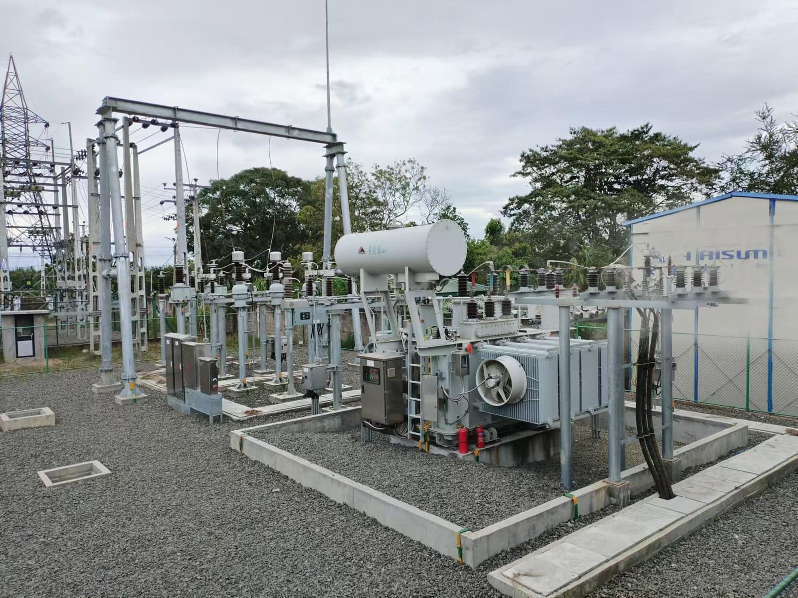
One of the most pressing challenges in transformer operation is fault protection. Power transformers face risks such as short circuits, overloads, overvoltages, insulation failures, and oil leaks. Without adequate protection, these faults can escalate into catastrophic transformer failures, costly downtime, and fire hazards. The solution is to deploy protective devices that can detect faults quickly, isolate the transformer, and prevent further damage. These devices safeguard not only the transformer but also the entire electrical network connected to it.
Protective devices safeguard transformers from faults by detecting abnormal conditions such as overcurrent, overvoltage, overheating, or internal failures and then initiating corrective actions like tripping circuit breakers, isolating the faulty section, or absorbing surges. Common protective devices include fuses, circuit breakers, protective relays, Buchholz relays, surge arresters, and temperature/pressure sensors. Together, they prevent damage, enhance transformer lifespan, and improve overall power system reliability.
These devices are not optional but mandatory for ensuring compliance with IEC, IEEE, and ANSI standards, as well as protecting investments worth millions.
Protective devices in transformers are only necessary for high-voltage applications.False
Protective devices are required for both low-voltage and high-voltage transformers to ensure safety and reliability.
The Buchholz relay is a key protective device for oil-immersed transformers.True
The Buchholz relay detects gas accumulation and oil flow caused by internal faults, providing early fault detection.
1. Common Protective Devices for Transformers
| Protective Device | Function | Application |
|---|---|---|
| Fuses | Protect against overcurrent by melting when current exceeds safe limit. | Small distribution transformers. |
| Circuit Breakers | Interrupt fault current automatically when triggered by protective relays. | Medium and large power transformers. |
| Protective Relays (Overcurrent, Differential, Distance) | Detect abnormal current/voltage conditions and send trip signals. | Transmission and substation transformers. |
| Buchholz Relay | Detects gas buildup and oil flow due to internal arc or winding fault. | Oil-immersed transformers (>500 kVA). |
| Surge Arresters | Divert lightning or switching surges safely to ground. | All transformers, particularly in HV/EHV. |
| Temperature Sensors (RTDs, Thermistors) | Monitor winding and oil temperature to prevent overheating. | Distribution and power transformers. |
| Pressure Relief Devices (PRD) | Release excess gas/oil pressure to prevent tank rupture. | Oil-filled transformers. |
2. Key Protection Principles
a) Overcurrent and Overload Protection
Overloads cause excessive heating in windings, which accelerates insulation aging. Overcurrent relays and thermal relays detect overloads and trigger alarms or trips.
b) Differential Protection
The most effective method for detecting internal transformer faults. Differential relays compare current entering and leaving the transformer—any difference indicates an internal fault.
c) Gas and Oil Protection
Buchholz relays provide early warning of insulation failure or arcing by detecting gas bubbles in transformer oil.
d) Surge and Lightning Protection
Metal-oxide surge arresters absorb high-energy impulses and protect transformer insulation.
e) Thermal and Pressure Protection
Temperature sensors and PRDs prevent overheating and tank explosions by monitoring oil and winding conditions.
3. Comparative Overview of Transformer Protection
| Fault Type | Typical Protective Device | Response |
|---|---|---|
| Short Circuit (internal/external) | Differential relay + circuit breaker | Immediate trip to isolate fault. |
| Overload | Thermal relay, overcurrent relay | Alarm or delayed trip. |
| Internal Arc / Insulation Breakdown | Buchholz relay | Alarm (gas buildup) or trip (sudden oil surge). |
| Lightning Surge | Surge arrester | Absorbs impulse, diverts to ground. |
| Overheating | RTD, oil thermometer | Alarm or cooling fan activation. |
| Tank Overpressure | PRD (Pressure Relief Device) | Releases pressure safely. |
4. Standards for Transformer Protection
- IEC 60076-7: Thermal protection and monitoring guidelines.
- IEEE C37 Series: Standards for protective relays and circuit breakers.
- ANSI C57.12.00: Transformer protection and test requirements.
- National Electrical Code (NEC): Grounding and overcurrent protection requirements.
What Role Do Relays, Circuit Breakers, and Fuses Play in Protection?
Transformers are among the most valuable and vulnerable components in power systems. Without adequate protection, faults like short circuits, overloads, insulation breakdowns, or lightning surges can lead to catastrophic transformer failure, costly outages, and even safety hazards for personnel. To prevent these risks, utilities and industries rely on relays, circuit breakers, and fuses as the three primary protective devices. Each plays a different role: relays detect abnormalities, circuit breakers interrupt fault currents, and fuses provide a fast and simple fail-safe against excessive current. When combined, they create a coordinated defense system that safeguards transformers and ensures uninterrupted power delivery.
Relays, circuit breakers, and fuses work together to protect transformers by detecting, isolating, and interrupting fault conditions. Relays continuously monitor electrical parameters and send trip signals when abnormalities occur. Circuit breakers respond to these signals and mechanically disconnect the faulty circuit to prevent damage. Fuses provide overcurrent protection by melting under excessive current, offering simple, fast protection for smaller transformers. Together, these devices ensure transformer safety, minimize downtime, and protect surrounding equipment.
This layered protection ensures compliance with IEC, IEEE, and ANSI safety standards, while extending transformer lifespan and reliability.
Relays alone can protect transformers by disconnecting the faulty circuit.False
Relays only detect and signal faults; circuit breakers or fuses are needed to physically interrupt current flow.
Fuses are commonly used in small distribution transformers for overcurrent protection.True
Fuses provide cost-effective, reliable fault protection for pole-mounted and pad-mounted distribution transformers.
1. Relays: The Detection System
Relays act as the brain of transformer protection. They continuously measure electrical parameters such as current, voltage, frequency, and differential current. When they detect abnormal conditions (e.g., short circuit, overload, ground fault), they send a trip signal to the circuit breaker.
Types of Relays Used in Transformers:
- Overcurrent relays: Trigger during excessive current flow.
- Differential relays: Detect internal faults by comparing currents at transformer input and output.
- Buchholz relay: Detects gas formation or oil movement inside oil-immersed transformers.
- Distance relays: Used in transmission protection where fault location is distance-dependent.
Relays alone cannot interrupt current—they only signal the breaker to act.
2. Circuit Breakers: The Interruption System
Circuit breakers are the muscle of transformer protection. Once the relay detects a fault, it instructs the breaker to open its contacts and isolate the transformer from the faulty circuit.
Functions:
- Interrupt high fault currents safely.
- Allow controlled reclosing after temporary faults.
- Prevent cascading failures across the power grid.
Breaker Types in Transformer Protection:
- Air Circuit Breakers (ACB) – Low-voltage applications.
- Vacuum Circuit Breakers (VCB) – Medium-voltage distribution systems.
- SF₆ Circuit Breakers – High-voltage networks, offering arc-extinguishing capabilities.
Circuit breakers make it possible to reset and restore service after faults are cleared, unlike fuses which must be replaced.
3. Fuses: The Fail-Safe Protection
Fuses provide the simplest form of overcurrent protection. They are sacrificial devices designed to melt when current exceeds a rated value, breaking the circuit instantly.
Applications:
- Widely used in pole-mounted distribution transformers (25–500 kVA).
- Backup protection in smaller transformers where breakers may not be practical.
- Protect against short circuits and severe overloads.
Advantages: Low cost, simple installation, very fast response time.
Limitations: Cannot be reset—must be replaced after operation.
4. Comparative Overview of Roles
| Device | Primary Function | Typical Use | Advantage | Limitation |
|---|---|---|---|---|
| Relays | Detect faults and issue trip commands | All sizes of transformers | Smart, selective protection | Cannot interrupt current |
| Circuit Breakers | Isolate faulty circuits by interrupting current | Medium & large transformers | Resettable, reliable | Higher cost, complex maintenance |
| Fuses | Provide direct overcurrent interruption | Small distribution transformers | Simple, low cost, fast | Non-resettable, limited selectivity |
5. Coordinated Protection in Action
When a fault occurs:
- The relay detects it (e.g., differential current inside transformer).
- The relay sends a trip signal to the circuit breaker.
- The circuit breaker opens, isolating the transformer.
- If it’s a small distribution transformer, the fuse blows instantly, protecting it without requiring a relay or breaker.
This coordination ensures the transformer is protected under all fault conditions—from minor overloads to catastrophic short circuits.
How Can Surge Arresters and Insulation Coordination Prevent Damage?
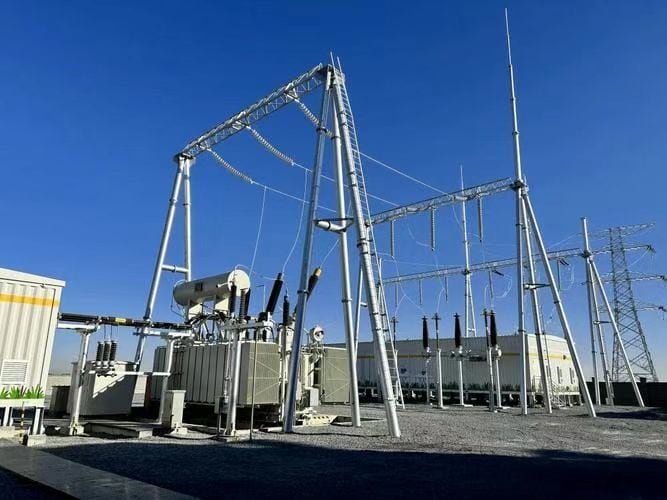
One of the greatest threats to transformer health is overvoltage stress caused by lightning strikes, switching operations, or grid disturbances. Such surges can exceed the insulation capacity of transformer windings, leading to dielectric breakdown, flashovers, and catastrophic failures. Repairing or replacing a damaged transformer is extremely costly and time-consuming. The solution lies in combining surge arresters with proper insulation coordination, ensuring that overvoltages are absorbed or diverted safely before they can damage the insulation system. This proactive design not only prevents equipment damage but also significantly improves transformer lifespan and system reliability.
Surge arresters and insulation coordination prevent transformer damage by limiting overvoltage stresses to safe levels. Surge arresters divert excessive transient voltages to ground, protecting windings and bushings, while insulation coordination ensures that insulation levels across the system are designed to withstand expected surges. Together, they prevent insulation breakdown, reduce failure risk, and enhance system reliability in both lightning-prone and switching-intensive networks.
This combined approach is a mandatory requirement under IEC 60071, IEEE C62, and ANSI C57 standards for transformer safety and reliability.
Surge arresters eliminate the need for insulation coordination.False
Surge arresters reduce transient voltages, but insulation levels must still be designed to withstand residual surges.
Proper insulation coordination ensures that the transformer insulation is neither under-designed nor excessively overdesigned.True
Balanced insulation levels optimize reliability, performance, and cost-effectiveness.
1. Role of Surge Arresters in Transformer Protection
Surge arresters are installed at transformer terminals to absorb and discharge high-energy surges into the ground, keeping residual voltage within safe limits.
Types of Surge Arresters:
- Gapless Metal-Oxide (ZnO) Arresters: Most common, highly reliable with nonlinear resistance.
- Silicon Carbide Arresters (with gaps): Older type, now mostly replaced.
Functions in Transformer Protection:
- Divert lightning surges away from windings.
- Absorb switching surges during capacitor bank operations or line energization.
- Minimize mechanical and thermal stress on insulation.
2. Insulation Coordination Principles
Insulation coordination ensures that the insulation withstands the residual voltage left after surge arrester operation. It involves selecting appropriate insulation levels based on:
- BIL (Basic Insulation Level): Ability of insulation to withstand lightning impulses.
- SIL (Switching Impulse Level): Withstand capability against switching surges.
- CFO (Critical Flashover Voltage): Maximum voltage before flashover occurs.
Proper coordination balances cost, reliability, and safety—overdesigning insulation increases cost, while underdesign risks failure.
3. Comparative Overview of Surge Protection
| Protection Measure | Function | Limitation if Used Alone |
|---|---|---|
| Surge Arresters | Clamp transient overvoltages and divert energy to ground. | Cannot guarantee safety if insulation is weak. |
| Insulation Coordination | Ensures insulation withstands expected residual voltages. | Cannot suppress surges without arresters. |
| Combined Approach | Arresters limit surge + insulation resists residual voltage. | Industry best practice under IEC/IEEE. |
4. Case Example: Lightning Strike on a Distribution Transformer
- A 33 kV overhead line feeding a transformer is struck by lightning.
- Without protection: Surge >400 kV enters transformer, exceeding winding insulation (BIL 170 kV). Catastrophic failure occurs.
- With surge arrester: Surge clamped to \~110 kV residual voltage.
- With insulation coordination: Transformer insulation (BIL 170 kV) withstands residual surge easily.
- Result: No damage, uninterrupted service.
5. Standards Governing Surge Protection
- IEC 60071: Insulation coordination for power systems.
- IEEE C62 Series: Surge arresters and surge protection standards.
- ANSI C57.12: Transformer dielectric test requirements.
6. Comparative Data Table – Surge Protection Effectiveness
| Scenario | Surge Voltage (kV) | Residual Voltage after Arresters (kV) | Transformer BIL (kV) | Result |
|---|---|---|---|---|
| No Protection | 400 | 400 | 170 | Failure |
| Surge Arrester Only | 400 | 110 | 170 | Safe (narrow margin) |
| Arrester + Insulation Coordination | 400 | 110 | 170 (well coordinated) | Safe & Reliable |
What Are the Industry Best Practices for Ensuring Reliable Grounding and Protection?
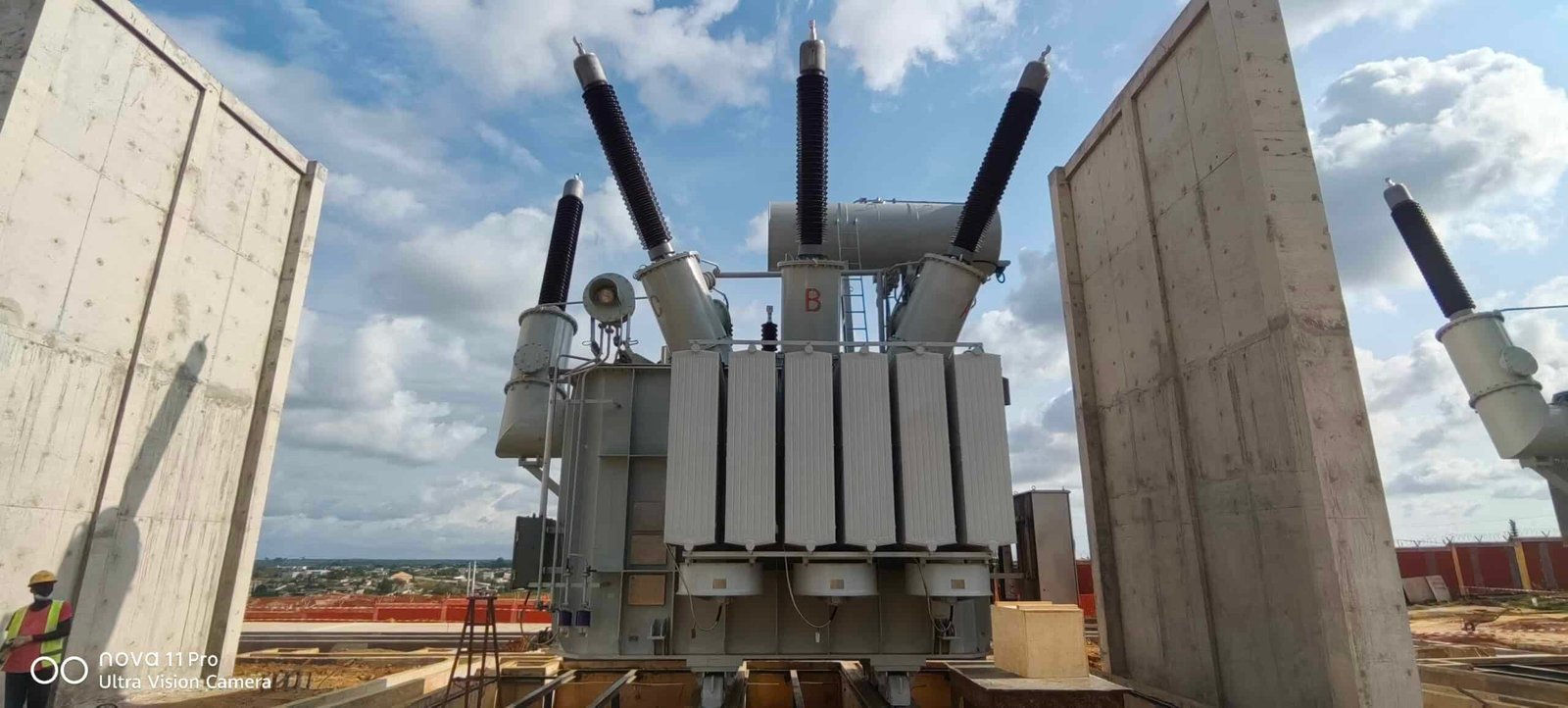
Transformers are among the most valuable and sensitive assets in an electrical network, and without proper grounding and protection, they are exposed to risks such as fault currents, lightning strikes, switching surges, overloading, and insulation failures. Inadequate protection not only results in unplanned outages and costly repairs but also compromises personnel safety and regulatory compliance. To avoid these issues, utilities and industries adopt best practices in grounding and protective coordination, ensuring that transformers operate safely, efficiently, and reliably throughout their service life.
Industry best practices for ensuring reliable grounding and protection include establishing a low-resistance grounding system (grid or rod-based), using protective relays and circuit breakers for fault detection and isolation, applying surge arresters with proper insulation coordination, installing Buchholz relays and temperature/pressure monitoring for early fault detection, and adhering to international standards (IEC, IEEE, ANSI) for design, testing, and safety compliance. Together, these measures protect transformers from electrical, thermal, and mechanical stresses while extending their lifespan.
Reliable grounding and protection are not optional—they are critical for long-term asset integrity, operational safety, and uninterrupted power delivery.
A transformer can operate safely without grounding if other protection devices are in place.False
Grounding is essential for fault current dissipation, system stability, and personnel safety. Protective devices cannot fully compensate for lack of grounding.
Best practices in transformer grounding and protection follow strict international standards like IEC 60076, IEEE C37, and ANSI C57.True
Compliance with international standards ensures reliability, safety, and interoperability across global markets.
1. Best Practices in Transformer Grounding
Grounding ensures that fault currents are safely directed into the earth, protecting equipment and personnel.
- Grounding Grid: Install a buried copper or galvanized steel grid around substations for low-resistance paths.
- Neutral Grounding: Choose grounding method (solid, resistance, or reactance) depending on system requirements.
- Equipotential Bonding: Bond metallic enclosures, tanks, and structures to avoid dangerous touch and step potentials.
- Soil Resistivity Testing: Regularly measure soil resistivity to ensure grounding effectiveness.
2. Protective Devices and Coordination
| Device | Function | Best Practice |
|---|---|---|
| Relays (Differential, Overcurrent, Thermal) | Detect abnormal currents/voltages. | Use microprocessor-based relays with programmable logic. |
| Circuit Breakers | Isolate faulted sections. | Select with appropriate interrupting capacity and reclosing schemes. |
| Fuses | Provide simple, fast fault isolation. | Use in small distribution transformers. |
| Buchholz Relay | Detects gas/oil movement in oil-immersed transformers. | Mandatory for units >500 kVA. |
| Surge Arresters | Clamp lightning/switching surges. | Install at transformer terminals and coordinate with insulation levels. |
| Temperature/Pressure Sensors | Monitor oil/winding conditions. | Integrate with SCADA for real-time monitoring. |
3. Insulation Coordination with Surge Protection
- Select Basic Insulation Level (BIL) according to IEC 60071.
- Match surge arrester protective level with transformer insulation withstand.
- Perform insulation coordination studies during transformer design.
4. Operational and Maintenance Practices
- Routine Testing: Insulation resistance, dissolved gas analysis (DGA), partial discharge tests.
- Online Monitoring: Temperature, moisture-in-oil, dissolved gases, and load monitoring.
- Periodic Grounding Audits: Ensure grounding resistance remains within safe limits (<1–5 Ω).
- Protection Relay Settings Review: Adjust relay coordination with system upgrades.
5. International Standards and Compliance
| Standard | Focus Area | Importance |
|---|---|---|
| IEC 60076 | Power transformer design and testing. | Ensures design reliability. |
| IEC 60071 | Insulation coordination. | Defines withstand levels. |
| IEEE C37 | Protection relays and circuit breakers. | Ensures reliable fault clearing. |
| ANSI C57 | Transformer protection/testing. | US compliance and safety. |
| NEC (NFPA 70) | Grounding and wiring rules. | Ensures installation safety. |
6. Data Comparison – Grounding Methods
| Grounding Type | Fault Current Control | Safety | Application |
|---|---|---|---|
| Solid Grounding | High | Excellent | LV/MV systems. |
| Resistance Grounding | Limited | Good | Industrial networks. |
| Reactance Grounding | Limited | Good | Large HV systems. |
| Isolated Neutral | None | Poor | Rarely used (risk of overvoltages). |
Conclusion
Best practices for grounding and protection of power transformers involve a combination of proper grounding methods, advanced protective devices, and coordinated insulation strategies. By ensuring safe fault current dissipation, accurate fault detection, and effective overvoltage protection, operators can achieve reliable transformer operation and extend equipment lifespan. Ultimately, grounding and protection systems are vital investments in both safety and long-term performance.
FAQ
Q1: Why is grounding important for power transformers?
Grounding provides a low-impedance path for fault currents, stabilizes system voltage, and improves personnel and equipment safety. Without proper grounding, transient overvoltages and insulation failures can cause catastrophic transformer damage.
Q2: What are the common grounding methods for transformers?
Solidly Grounded: Used in distribution systems for effective fault clearing.
Resistance Grounded: Limits fault current to protect equipment.
Reactance Grounded: Applied in high-voltage systems to control fault levels.
Ungrounded (Isolated Neutral): Rarely used, only in special cases where continuity is critical.
Q3: What protection systems are essential for power transformers?
Key protection schemes include:
Differential Protection (87T): Detects internal winding faults.
Buchholz Relay (for oil-filled transformers): Senses gas buildup due to internal faults.
Overcurrent Protection (50/51): Protects against external faults and overloads.
Overvoltage & Surge Arresters: Prevent damage from lightning or switching surges.
Temperature Protection: Monitors winding and oil temperature to prevent overheating.
Q4: How can grounding and protection improve transformer reliability?
Proper grounding minimizes insulation stress and fault damage, while protection systems detect and isolate abnormal conditions before they escalate. Together, they extend transformer life, reduce downtime, and enhance grid stability.
Q5: What are best practices for transformer grounding and protection?
Use dedicated earth electrodes with low resistance.
Ensure proper lightning arresters and surge protection devices are installed.
Regularly test protective relays and devices for accuracy.
Maintain oil testing and dissolved gas analysis (DGA) for early fault detection.
Follow IEEE C57 and IEC 60076 guidelines for grounding and protection standards.
References
IEEE Std C57 – Transformer Protection and Grounding: https://ieeexplore.ieee.org
IEC 60076 – Transformer Safety and Protection Guidelines: https://webstore.iec.ch
NEMA – Transformer Grounding Best Practices: https://www.nema.org
Electrical4U – Transformer Protection Systems Explained: https://www.electrical4u.com
EEP – Transformer Grounding and Earthing Methods: https://electrical-engineering-portal.com
All About Circuits – Transformer Protection Basics: https://www.allaboutcircuits.com
Energy.gov – Transformer Safety and Reliability Practices: https://www.energy.gov


