Power transformers are critical assets in electrical networks, and identifying faults at an early stage is vital to prevent failures, costly downtime, or safety hazards. Common transformer faults can often be detected through careful observation, routine testing, and monitoring of key indicators. This guide outlines how to recognize common malfunctions and the techniques used to diagnose them.
What Are the Typical Faults in Power Transformers?
![]()
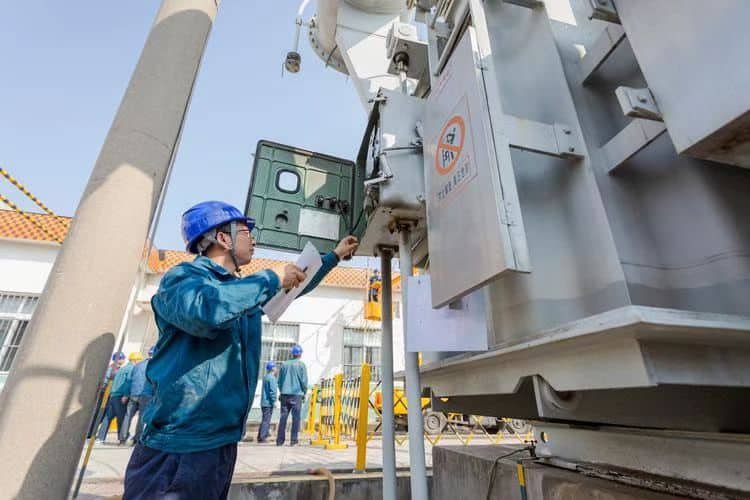
Power transformers are designed for long-term reliability, often serving for 30–40 years, but they are not immune to faults. Electrical, thermal, and mechanical stresses accumulate over time, leading to degradation or sudden failures. The consequences can be severe: extended outages, costly repairs, fire hazards, and even grid instability. Understanding the typical faults that occur inside transformers is essential for effective monitoring, maintenance, and preventive measures.
The most common faults in power transformers include winding insulation breakdown, short-circuits, overloading and overheating, core faults, oil leaks and degradation, bushing failures, and tap changer malfunctions. These faults are caused by electrical stresses, thermal aging, mechanical shocks, or contamination, and they can be detected through methods such as dissolved gas analysis (DGA), thermal imaging, and protective relay systems.
Recognizing these faults early ensures safe operation, reduced downtime, and extended transformer lifespan.
Transformer failures are mostly random and cannot be predicted or prevented.False
Most transformer faults develop gradually and can be detected early through advanced monitoring techniques like DGA and thermal sensors.
On-load tap changer (OLTC) failures are one of the leading causes of transformer outages.True
OLTCs are moving parts subject to wear, arcing, and contact degradation, making them common points of failure.
1. Typical Fault Categories in Power Transformers
| Fault Type | Description | Common Causes | Detection Methods |
|---|---|---|---|
| Insulation Breakdown | Loss of dielectric strength in windings | Aging, moisture, overvoltage | DGA, insulation resistance test |
| Winding Short-Circuit | Partial/complete short between turns | Electrical surge, thermal stress | FRA, protective relays |
| Core Faults | Hot spots or circulating currents in core | Lamination damage, grounding issues | Thermal imaging, acoustic methods |
| Oil Degradation/Leaks | Loss of cooling and insulation | Oxidation, poor seals | Oil testing, leak inspections |
| Bushing Failures | Breakdown of high-voltage bushings | Surface contamination, partial discharge | Infrared, capacitance & power factor tests |
| Tap Changer Faults | Contact wear, arcing, overheating | Frequent switching, poor lubrication | DGA, OLTC monitoring |
| Overheating/Overload | Excessive current or poor cooling | Load growth, blocked radiators | Temperature sensors, SCADA |
2. Key Examples of Transformer Faults
- Insulation Failure: One of the most severe, leading to flashover or complete transformer breakdown.
- Winding Deformation: Caused by mechanical forces during short-circuit faults, resulting in loss of impedance balance.
- Partial Discharge (PD): Small electrical sparks inside insulation that gradually degrade dielectric materials.
- Gas Generation in Oil: Overheating or arcing produces gases (H₂, CH₄, C₂H₂), detectable via DGA.
- Tap Changer Arcing: Produces carbon deposits and overheating, a major source of failures.
3. Case Study Example
A 400 MVA, 400 kV transformer in Europe failed after a winding short-circuit caused by insulation degradation. DGA prior to failure showed rising acetylene and hydrogen levels, but monitoring was irregular. The result was catastrophic failure, requiring full replacement at a cost of over \$10 million. A continuous online monitoring system could have prevented the incident.
4. Comparative Failure Contribution by Component
| Component | Contribution to Transformer Failures (%) |
|---|---|
| Winding/Insulation | 35% |
| Tap Changer (OLTC) | 30% |
| Bushings | 15% |
| Core & Tank | 10% |
| Cooling System | 5% |
| Others | 5% |
5. Preventive Measures
- Regular dissolved gas analysis (DGA) for early detection.
- Frequency Response Analysis (FRA) for winding deformation.
- Online thermal and load monitoring to prevent overheating.
- Preventive OLTC maintenance to reduce switching failures.
- Use of protective relays to trip faulty transformers before catastrophic failure.
How Can Visual Inspections Help Detect Early Issues?
Power transformers are high-value assets, and their failure can cause costly outages, equipment damage, and safety risks. While advanced monitoring tools such as dissolved gas analysis (DGA) and thermal sensors are essential, many early signs of transformer issues can be spotted through simple visual inspections. Neglecting regular physical checks can allow small problems—like oil leaks, corrosion, or overheating—to escalate into major failures. The solution is a structured visual inspection program as part of preventive maintenance.
Visual inspections help detect early transformer issues by identifying physical abnormalities such as oil leaks, corrosion, discoloration, bushing cracks, loose connections, or unusual noises. These visible warning signs often precede more severe internal faults and allow operators to take corrective action before equipment failure occurs. Regular inspections reduce risks, extend transformer lifespan, and lower maintenance costs.
A visual inspection is a low-cost yet highly effective tool that complements advanced diagnostic methods.
Transformer failures always occur suddenly without prior warning signs.False
Most transformer failures are preceded by physical symptoms such as leaks, overheating, or unusual noises, which can be observed during visual inspections.
Visual inspections are unnecessary if advanced monitoring systems are installed.False
Visual inspections are still essential because they detect external issues that sensors may not capture, such as physical damage or vandalism.
1. What Issues Can Visual Inspections Detect?
| Inspection Focus | Potential Issue Identified | Warning Sign |
|---|---|---|
| Bushings | Cracks, tracking, oil leakage | Surface cracks, discoloration |
| Cooling System | Blocked radiators, fan failure | Dust buildup, inactive fans |
| Oil Levels | Leaks or low oil level | Wet patches, oil on ground |
| Tank & Core | Corrosion, deformation | Rust, dents |
| Connections | Loose joints, overheating | Burn marks, discoloration |
| Grounding | Loose or broken ground | Visible wire damage |
| Noise & Vibration | Mechanical stress or loose parts | Humming, rattling |
2. Typical Visual Symptoms and Their Implications
- Oil Leaks: Signal gasket deterioration or tank damage; can reduce insulation and cooling capacity.
- Discolored Paint or Burn Marks: Indicate overheating or arcing inside the transformer.
- Cracked Bushings: Compromise insulation, increasing risk of flashover.
- Rust and Corrosion: Lead to tank weakening and possible oil contamination.
- Unusual Sounds: A louder-than-normal hum may point to winding displacement or core vibration.
- Moisture Accumulation: Suggests breather malfunction, leading to insulation degradation.
3. Case Example
At a utility substation, a minor oil stain was observed under a 220 kV transformer during a routine visual inspection. Upon further testing, it was revealed that the conservator tank gasket was degrading. Timely replacement prevented a catastrophic oil loss and saved the utility an estimated \$500,000 in potential downtime and repair costs.
4. Benefits of Routine Visual Inspections
| Benefit | Explanation |
|---|---|
| Early Fault Detection | Catches problems before they escalate |
| Low Cost | Requires minimal tools and training |
| Complements Digital Monitoring | Provides physical evidence alongside sensor data |
| Improves Safety | Identifies hazards like oil spills or exposed connections |
| Extends Lifespan | Prevents premature transformer failure |
5. Best Practices for Visual Inspections
- Perform inspections monthly or after severe weather events.
- Use a checklist covering bushings, tank, oil, cooling, and grounding.
- Record all findings with photos and reports for trend analysis.
- Train staff to distinguish between normal wear and warning signs.
- Combine inspections with infrared thermography for hotspots.
What Electrical and Thermal Signs Indicate Malfunctions?
Transformers rarely fail without warning. Long before a catastrophic fault occurs, they usually exhibit electrical and thermal warning signs that operators can detect through monitoring or routine checks. If ignored, these signs can escalate into insulation breakdown, winding deformation, or even fire. Early detection of anomalies in voltage, current, or temperature profiles helps operators take corrective action, extending transformer life and avoiding costly outages.
Typical electrical signs of transformer malfunctions include overvoltage, undervoltage, current imbalance, excessive harmonics, partial discharge, and abnormal insulation resistance. Thermal signs include overheating, hot spots in windings or core, uneven cooling, and abnormal oil temperature rise. These indicators are measurable through protective relays, thermal sensors, dissolved gas analysis (DGA), and infrared thermography, allowing early detection and intervention.
Monitoring these parameters ensures safe, efficient, and reliable transformer operation.
Transformer malfunctions always occur suddenly, with no measurable indicators.False
Most malfunctions show gradual changes in electrical or thermal behavior that can be monitored and detected in advance.
Thermal imaging can identify early overheating issues in transformers without invasive testing.True
Infrared thermography is widely used to detect hotspots on bushings, windings, and cooling components before failure.
1. Electrical Signs of Transformer Malfunction
| Electrical Indicator | Possible Cause | Monitoring Method |
|---|---|---|
| Overvoltage/Undervoltage | Tap changer failure, load fluctuation | Voltage sensors, SCADA |
| Current Imbalance | Winding fault, short-circuit, phase loss | Protective relays, CTs |
| Excessive Harmonics | Nonlinear loads stressing windings | Harmonic analyzers |
| Partial Discharge (PD) | Insulation deterioration, voids | PD detectors, acoustic sensors |
| Low Insulation Resistance | Moisture, aging insulation | Megger testing |
| Abnormal Differential Current | Internal fault, winding short | Differential relays |
2. Thermal Signs of Transformer Malfunction
| Thermal Indicator | Possible Cause | Detection Technique |
|---|---|---|
| Hot Spots in Windings | Overload, poor cooling, insulation failure | Fiber optic sensors, thermal models |
| Uneven Cooling | Blocked radiators, fan/pump failure | Infrared thermography |
| Oil Temperature Rise | Overload, oxidation, gassing | Oil temperature sensors, DGA |
| Localized Overheating | Core faults, circulating currents | Thermal imaging, hotspot sensors |
| Abnormal Ambient to Oil Gradient | Poor heat dissipation | Online thermal monitoring |
3. Case Example
In an Asian utility, operators noticed a gradual rise in transformer oil temperature despite normal load conditions. Infrared imaging confirmed a hotspot near one bushing. Subsequent inspection revealed carbonized deposits caused by partial discharge. By replacing the bushing in time, the utility prevented a major failure that could have led to a full transformer replacement costing over \$2 million.
4. Electrical vs. Thermal Indicators – Comparative View
| Aspect | Electrical Signs | Thermal Signs |
|---|---|---|
| Nature | Related to current, voltage, and insulation performance | Related to heat buildup and cooling efficiency |
| Early Detection | Relays, meters, insulation tests | Thermal sensors, infrared imaging |
| Common Causes | Short circuits, harmonics, poor insulation | Overloads, cooling failures, oil degradation |
| Failure Risk | High—may cause sudden trips | High—may cause gradual degradation |
5. Best Practices for Monitoring
- Install online DGA systems to detect thermal and electrical fault gases.
- Use infrared thermography during visual inspections for hotspots.
- Apply differential and overcurrent relays to capture abnormal electrical behavior.
- Monitor load cycles to correlate electrical stresses with thermal performance.
- Perform regular insulation resistance and tan delta tests to detect degradation.
How Do Diagnostic Tests Help Identify Faults?

Transformers are complex, long-life assets, and their failure can cause millions in repair and downtime costs. Many faults—such as insulation breakdown, winding deformation, and oil degradation—develop slowly, giving early warning signals before catastrophic failure. Relying only on visible symptoms is risky; that’s why diagnostic testing is essential. These tests allow operators to detect hidden issues, understand asset health, and take preventive action before problems escalate.
Diagnostic tests help identify transformer faults by measuring key electrical, chemical, and thermal parameters. Tests such as dissolved gas analysis (DGA), insulation resistance, frequency response analysis (FRA), power factor testing, and infrared thermography can reveal internal degradation, overheating, partial discharges, winding deformations, and oil contamination. Together, these tests provide a comprehensive picture of transformer condition, enabling predictive maintenance and preventing unexpected failures.
With proper diagnostic testing, operators gain early insight into transformer health, extending lifespan and reducing costly outages.
Transformers usually fail without any detectable warning signs.False
Most failures are preceded by measurable changes in electrical, chemical, or thermal properties, detectable with diagnostic testing.
Dissolved gas analysis (DGA) is the most widely used method to detect early-stage internal transformer faults.True
DGA identifies gases generated by overheating, arcing, and insulation breakdown, serving as a critical early warning tool.
1. Key Diagnostic Tests and Their Functions
| Test Name | Faults Detected | Principle |
|---|---|---|
| Dissolved Gas Analysis (DGA) | Overheating, arcing, insulation breakdown | Detects gases dissolved in transformer oil |
| Insulation Resistance Test (Megger) | Insulation aging, moisture ingress | Measures resistance of insulation materials |
| Frequency Response Analysis (FRA) | Winding deformation, core displacement | Compares frequency response curves |
| Power Factor / Tan Delta Test | Insulation deterioration, partial discharge | Measures dielectric losses |
| Infrared Thermography | Hot spots, cooling failures | Detects abnormal heat patterns |
| Sweep Frequency Response | Winding movement after faults | Identifies structural shifts |
| Oil Quality Testing | Acidity, moisture, breakdown strength | Assesses oil’s insulating and cooling ability |
2. Electrical vs. Chemical vs. Thermal Diagnostic Methods
| Category | Examples | Faults Detected | Frequency |
|---|---|---|---|
| Electrical | FRA, insulation resistance, power factor | Winding faults, insulation issues | Yearly / after major faults |
| Chemical | DGA, oil quality, furan analysis | Overheating, insulation paper aging | Quarterly to annually |
| Thermal | Infrared imaging, fiber-optic sensors | Hotspots, cooling inefficiency | Continuous or periodic |
3. Case Study Example
At a 500 MVA, 400 kV transformer in India, dissolved gas analysis showed rising levels of acetylene and hydrogen, which pointed to arcing. Operators carried out infrared thermography, confirming a localized hotspot. Further FRA testing revealed winding displacement. Thanks to layered diagnostic testing, the transformer was removed from service before catastrophic failure, saving the utility over \$8 million in replacement and outage costs.
4. Benefits of Transformer Diagnostic Testing
- Early fault detection before catastrophic failures
- Predictive maintenance planning instead of reactive repairs
- Extended asset lifespan by addressing minor issues early
- Lower lifecycle costs due to fewer emergency replacements
- Improved grid reliability and safety through proactive measures
5. Best Practices
- Implement a diagnostic testing schedule (monthly, quarterly, yearly depending on test type).
- Integrate online monitoring systems for continuous DGA and thermal data.
- Compare test results with historical trends for accurate fault prediction.
- Use third-party laboratories for independent oil and insulation analysis.
- Train maintenance staff in data interpretation to avoid misdiagnosis.
What Role Does Dissolved Gas Analysis (DGA) Play in Fault Detection?
Transformers operate under constant electrical, thermal, and mechanical stress, which gradually degrades insulation and oil. When overheating, arcing, or partial discharge occurs, the insulation and oil break down, releasing gases that dissolve into the transformer oil. If left unchecked, these processes lead to insulation failure, winding damage, or catastrophic breakdown. The challenge is that many of these internal faults cannot be seen from the outside—this is where Dissolved Gas Analysis (DGA) becomes invaluable.
Dissolved Gas Analysis (DGA) plays a critical role in transformer fault detection by measuring the types and concentrations of gases dissolved in insulating oil. Different gases correspond to different fault types—such as overheating, partial discharge, or arcing. By analyzing gas patterns and trends, operators can detect faults at an early stage, classify their severity, and take corrective actions before catastrophic failure occurs.
This makes DGA one of the most widely adopted predictive maintenance tools for power transformers worldwide.
DGA can detect early signs of insulation breakdown, overheating, and arcing inside transformers.True
Faults produce characteristic gases such as hydrogen, methane, acetylene, and ethylene, which dissolve into oil and can be detected through gas chromatography.
If a transformer passes a single DGA test, it will remain fault-free indefinitely.False
DGA must be performed regularly to track gas trends, as sudden increases can indicate emerging faults.
1. Key Gases and Their Diagnostic Significance
| Gas | Typical Source | Fault Indication |
|---|---|---|
| Hydrogen (H₂) | Partial discharges, corona | Low-energy electrical faults |
| Methane (CH₄) | Oil overheating at low temperatures | Thermal faults |
| Ethylene (C₂H₄) | High-temperature overheating of oil | Severe thermal faults |
| Acetylene (C₂H₂) | High-energy arcing | Electrical arcing faults |
| Carbon Monoxide (CO) | Paper insulation breakdown | Cellulose insulation degradation |
| Carbon Dioxide (CO₂) | Aging insulation, overheating | Insulation aging |
2. DGA Interpretation Methods
| Method | Approach | Advantage | Limitation |
|---|---|---|---|
| Key Gas Method | Identifies faults based on dominant gas type | Simple, widely used | Limited accuracy for complex faults |
| Rogers Ratio | Ratios of specific gases indicate fault type | More accurate fault classification | Requires stable gas levels |
| IEC Ratio Method | Uses defined gas ratios per IEC 60599 | Standardized and reliable | Needs periodic sampling |
| Duval Triangle | Graphical plotting of gas ratios | Highly reliable for complex faults | Requires expertise in interpretation |
3. Case Example
In a 220 kV transformer in South America, DGA detected a sharp rise in acetylene and hydrogen levels, pointing to arcing within the winding. No external signs were visible, and electrical tests appeared normal. However, operators took the unit offline, inspected it, and found a localized arcing fault due to deteriorated insulation. Because DGA caught the fault early, the repair cost was under \$200,000, compared to the \$3 million replacement cost had the unit failed in service.
4. Why DGA Is Critical in Fault Detection
- Early warning system before visible failure symptoms appear
- Non-invasive method—requires only an oil sample
- Identifies fault type (thermal, electrical, insulation-related)
- Tracks severity over time with trend analysis
- Supports predictive maintenance and optimized replacement planning
5. Best Practices for Effective DGA
- Conduct baseline DGA when the transformer is new.
- Sample oil quarterly for critical units and annually for standard units.
- Use online DGA monitors for real-time critical transformer protection.
- Always compare with historical data trends, not just single results.
- Combine with other tests (Furan, FRA, thermography) for full fault diagnosis.
How Can Predictive Maintenance Prevent Major Failures?
Power transformers are critical assets in electrical networks, often expected to operate reliably for 30–40 years. However, stresses from thermal cycling, electrical faults, and environmental conditions cause gradual deterioration of insulation, windings, oil, and mechanical components. If these issues remain undetected, they can escalate into catastrophic failures, leading to extended blackouts, multi-million-dollar losses, and safety hazards. Traditional time-based maintenance alone is no longer sufficient. The solution lies in predictive maintenance, which uses advanced diagnostics and real-time monitoring to anticipate problems before they occur.
Predictive maintenance prevents major transformer failures by continuously monitoring critical parameters such as dissolved gases, oil quality, temperature, and electrical signals to detect early signs of deterioration. By applying data analytics, trend analysis, and AI-based fault prediction, utilities can identify emerging problems, schedule timely interventions, avoid unexpected breakdowns, and extend asset lifespan.
This proactive approach ensures higher reliability, lower costs, and optimized maintenance cycles compared to corrective or time-based methods.
Predictive maintenance can detect transformer faults before they cause catastrophic failure.True
By analyzing data trends such as gas generation, insulation degradation, or hotspot temperatures, predictive maintenance identifies developing issues early.
Routine calendar-based maintenance is always more effective than predictive maintenance.False
Time-based maintenance may miss developing issues, while predictive approaches use real-time data for more precise interventions.
1. Key Elements of Predictive Maintenance in Transformers
| Monitoring Parameter | Faults Detected | Tools/Techniques |
|---|---|---|
| Dissolved Gas Analysis (DGA) | Overheating, arcing, insulation failure | Online DGA monitors |
| Oil Quality & Furan Analysis | Moisture, acidity, paper insulation aging | Oil sampling, lab analysis |
| Thermal Monitoring | Hot spots, cooling system inefficiency | Fiber-optic sensors, infrared thermography |
| Electrical Testing | Winding deformation, insulation breakdown | FRA, tan delta, partial discharge detection |
| Mechanical Monitoring | Tap changer wear, vibrations | Vibration sensors, acoustic monitoring |
2. How Predictive Maintenance Prevents Failures
- Early Fault Detection → Catches overheating, arcing, or insulation breakdown before catastrophic failure.
- Trend Analysis → Tracks gradual deterioration, allowing planned replacement of parts.
- Condition-Based Maintenance → Reduces unnecessary servicing while ensuring critical interventions are done on time.
- Improved Safety → Prevents oil fires, explosions, and bushing failures that pose safety risks.
- Optimized Asset Utilization → Extends transformer life by preventing accelerated degradation.
3. Case Study Example
A 400 MVA, 500 kV transformer in Europe showed rising ethylene and acetylene levels in online DGA readings. Predictive analytics flagged the trend as incipient arcing. Operators scheduled an inspection and discovered insulation degradation near a winding lead. Repairs were carried out during a planned outage, avoiding sudden failure. This proactive step saved over \$7 million in replacement and outage costs, proving predictive maintenance as a game-changer.
4. Benefits Compared to Other Maintenance Approaches
| Maintenance Type | Approach | Pros | Cons |
|---|---|---|---|
| Corrective | Repair after failure | Simple | High downtime, costly, unsafe |
| Preventive (Time-Based) | Scheduled at intervals | Predictable, planned | May over/under-service |
| Predictive (Condition-Based) | Uses data & monitoring | Early detection, cost-efficient, reliable | Requires sensors, analytics |
5. Best Practices for Implementing Predictive Maintenance
- Install online monitoring systems for critical transformers.
- Combine multiple tests (DGA, FRA, thermography) for holistic fault detection.
- Use AI and digital twin models to predict fault progression.
- Maintain historical performance databases for trend comparison.
- Train staff in data interpretation to avoid misdiagnosis.
Conclusion
Identifying common transformer faults requires a combination of inspection, monitoring, and testing. By recognizing warning signs—such as abnormal noises, overheating, gas generation, or insulation deterioration—operators can take corrective actions before minor issues escalate into major failures. Modern diagnostic tools and predictive maintenance strategies greatly enhance the ability to detect and address faults efficiently, ensuring transformer reliability and extended service life.
FAQ
Q1: What are the most common faults in power transformers?
The most frequent faults include:
Overheating due to overload or cooling failure.
Insulation breakdown caused by aging or moisture.
Oil leaks leading to reduced insulation and fire hazards.
Winding short circuits from mechanical stress.
Bushing failures due to contamination or cracking.
Protection relay malfunctions that fail to isolate faults.
Q2: How can overheating faults be identified?
Overheating is detected through:
Temperature gauges and thermal sensors in windings and oil.
Infrared thermography to identify hot spots.
Dissolved gas analysis (DGA) detecting gases like ethylene and methane, which indicate overheating.
Q3: How is insulation failure diagnosed?
Dielectric strength tests reveal reduced insulation performance.
Moisture analysis in oil indicates water contamination.
Partial discharge testing identifies insulation weak points before breakdown.
Q4: What are the signs of oil-related faults?
Oil leaks around gaskets, bushings, or tank seams.
Gas accumulation in Buchholz relay (in oil-filled transformers).
Darkened or acidic oil indicating oxidation and degradation.
Regular oil testing and DGA are essential to monitor oil health.
Q5: How can protection system faults be detected and prevented?
Protection faults occur when relays, circuit breakers, or sensors fail. Prevention includes:
Routine testing and calibration of protection relays.
Secondary injection testing to ensure relay accuracy.
SCADA monitoring for early detection of abnormal operations.
References
IEEE C57 – Transformer Fault Detection Standards: https://ieeexplore.ieee.org
IEC 60076 – Transformer Testing and Fault Guidelines: https://webstore.iec.ch
NEMA – Transformer Fault Diagnosis Practices: https://www.nema.org
Electrical4U – Common Transformer Faults Explained: https://www.electrical4u.com
EEP – Transformer Malfunction Diagnosis: https://electrical-engineering-portal.com
Energy.gov – Transformer Reliability and Maintenance: https://www.energy.gov