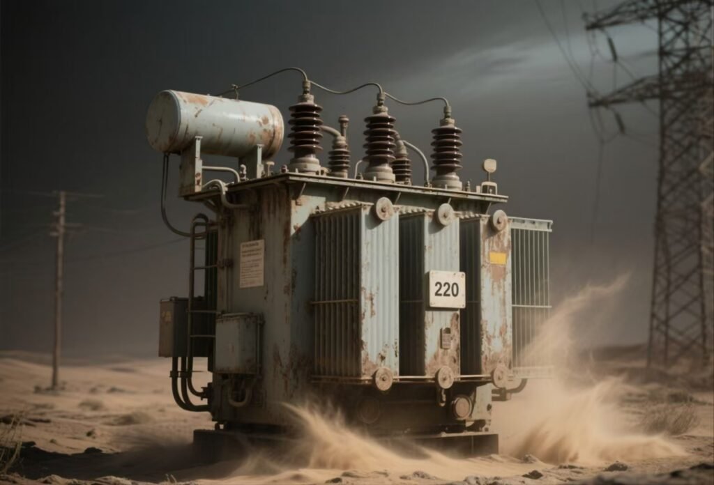
Transformers are critical assets in power systems, and their reliability is essential for uninterrupted electricity supply. In regions prone to seismic activity, transformer design must account for earthquake risks to ensure safety, structural integrity, and continuous operation. Earthquake-resistant designs involve specialized engineering measures that mitigate damage and enhance resilience.
Why Must Transformers Be Designed for Seismic Conditions?
Transformers are critical infrastructure assets that ensure stable power transmission and distribution. However, in earthquake-prone regions, they are also among the most vulnerable components of substations. Seismic events can cause structural damage, oil leaks, fire hazards, and complete transformer failure, leading to widespread blackouts and costly downtime. Beyond technical failures, transformer collapse can also endanger personnel safety and cause environmental contamination from spilled insulating oil. The solution lies in designing transformers specifically to withstand seismic stresses and vibrations, ensuring both operational continuity and public safety.
Transformers must be designed for seismic conditions because earthquakes generate horizontal and vertical forces that can compromise their structural integrity, insulation, and anchoring. Seismic-rated transformers use reinforced tanks, rigid core-and-coil assemblies, base anchoring systems, and flexible bushings to absorb shocks and vibrations. This ensures grid reliability, minimizes environmental risks from oil leakage, and complies with seismic safety standards.
This article explains why seismic considerations are essential in transformer design and what measures manufacturers take to ensure resilience.
Seismic Forces and Their Impact on Transformers
- Horizontal Vibrations
- Cause displacement of heavy transformer cores and windings.
- May lead to coil misalignment, insulation failure, and short circuits.
- Vertical Vibrations
- Stress bushings and connections, risking cracks and flashovers.
- Increase fatigue on support structures and foundations.
- Torsional (Twisting) Effects
- Can shift internal assemblies against the tank walls.
- May cause oil leaks from gaskets and welds.
- Foundation Stress
- Poor anchoring leads to tilting, sliding, or even overturning of large transformers.
Seismic Design Measures in Transformers
| Design Aspect | Seismic Solution |
|---|---|
| Core and Coil Assembly | Rigid clamping and bracing to prevent displacement under vibration |
| Tank and Frame | Reinforced steel with shock-resistant welds and stiffeners |
| Bushings and Connections | Flexible, vibration-absorbing designs to prevent cracking |
| Base Anchoring | Seismic-rated anchor bolts and foundation pads |
| Oil Preservation System | Reinforced conservators and flexible piping to prevent rupture |
Standards and Compliance Requirements
- IEEE 693: Specifies seismic qualification for substation equipment.
- IEC 60068-3-3: Covers seismic testing of electrical equipment.
- ASCE 7 & Building Codes: Require seismic-resistant foundations and anchoring.
Transformers installed in seismic zones can function safely without earthquake-resistant design.False
Seismic-rated design is critical because earthquakes impose dynamic loads that exceed normal mechanical stresses, risking transformer failure and safety hazards.
Why This Matters
Seismic-resistant transformer design ensures:
- Grid resilience during and after earthquakes.
- Safety of operating personnel by reducing collapse and fire hazards.
- Environmental protection by preventing oil spills.
- Compliance with international seismic safety regulations.
Would you like me to also explain how seismic testing is performed (shaking table simulations and finite element analysis) to prove transformer resilience before deployment?
How Do Earthquakes Physically Impact Transformer Structures?
Transformers are massive, rigid, and oil-filled machines—often weighing hundreds of tons—making them extremely vulnerable to earthquake forces. When an earthquake strikes, the violent ground accelerations, vibrations, and torsional stresses can displace, crack, or even topple transformers. This not only interrupts power supply but also creates fire hazards from ruptured tanks and oil leaks, while damaged bushings can trigger electrical faults or explosions. Without seismic-rated design, transformers risk catastrophic failure during strong tremors.
Earthquakes physically impact transformer structures by inducing horizontal, vertical, and torsional forces that stress the core-and-coil assemblies, tank walls, bushings, and foundations. Horizontal shaking can shift or misalign windings, vertical shocks may crack porcelain bushings, torsional forces twist tanks and internal bracing, and weak foundations risk sliding or overturning. These mechanical stresses lead to oil leaks, electrical faults, and permanent structural deformation.
To understand the severity, let’s break down the physical impacts in detail.
Key Earthquake-Induced Stresses on Transformers
| Impact Type | Effect on Transformer Structure | Risk Consequence |
|---|---|---|
| Horizontal Ground Motion | Shifts heavy core-and-coil assemblies; strains bracing clamps | Coil displacement → short circuits |
| Vertical Ground Motion | Applies sudden loads on bushings, radiators, and tank joints | Bushing cracks → flashover or failure |
| Torsional Twisting | Rotational forces deform tank welds and loosen fasteners | Oil leakage, tank rupture |
| Foundation Stress | Overturning or sliding if anchor bolts fail | Complete structural collapse |
| Vibration Fatigue | Repeated stress cycles on connections and welds | Accelerated aging, hidden cracks |
Real-World Example of Earthquake Impact
- 1995 Kobe Earthquake (Japan): Several large power transformers were destroyed due to inadequate anchoring, leading to fires and widespread outages.
- 2011 Tohoku Earthquake (Japan): Oil-filled transformers in substations suffered bushing breakages and oil spillage, causing localized blackouts.
Why Physical Impacts Matter
- Grid Reliability – Prevents sudden transformer failure during seismic events.
- Personnel Safety – Reduces risks of fire, oil explosions, or falling equipment.
- Environmental Protection – Avoids contamination from spilled insulating oil.
- Asset Longevity – Ensures transformers remain serviceable after earthquakes.
Earthquake forces mainly affect transformer electrical performance but not mechanical structures.False
Earthquakes primarily impose mechanical stresses—displacement, cracking, and vibration—that damage transformer tanks, windings, bushings, and foundations, leading secondarily to electrical failures.
Closing Thought
The physical impact of earthquakes on transformers is primarily mechanical, but its consequences extend to electrical reliability, environmental safety, and operational continuity. That’s why seismic design, reinforced anchoring, and compliance with IEEE 693 and IEC 60068 are essential for transformers deployed in seismic zones.
Would you like me to also detail the engineering reinforcements (anchoring, flexible bushings, tank stiffeners, etc.) that manufacturers add to reduce these earthquake impacts?
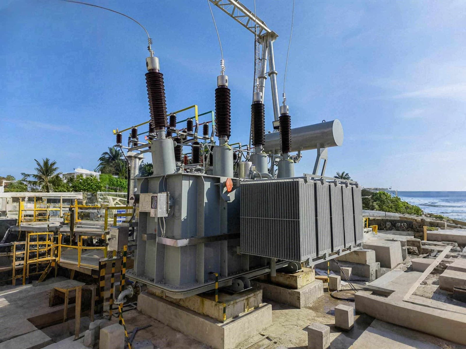
What Design Features Improve Seismic Resistance in Transformers?
![]()
Transformers installed in earthquake-prone regions face the dual challenge of carrying high electrical loads while resisting violent seismic forces. Without specialized design, earthquakes can displace coils, crack bushings, rupture tanks, and even overturn the transformer, leading to blackouts, fires, or environmental hazards. The solution is seismic-resistant transformer design, where structural reinforcements, damping mechanisms, and flexible components minimize earthquake-induced stresses.
Key design features that improve seismic resistance in transformers include reinforced tanks with stiffeners, rigid core-and-coil bracing, seismic anchoring bases, flexible bushings, vibration-absorbing supports, and oil preservation systems designed to withstand shocks. Together, these features ensure transformers remain stable, prevent oil leakage, and continue operating safely during and after seismic events.
Core and Coil Reinforcement
- Clamping Systems: Heavy-duty bracing clamps hold the winding and core securely to prevent displacement during horizontal and vertical shaking.
- Compression Frames: Provide uniform load distribution, reducing stress concentration on winding insulation.
Tank and Structural Strength
- Tank Stiffeners: Reinforced ribs and welded stiffeners on the tank wall resist buckling under torsional stress.
- Seismic-Grade Welds: Extra-strong welding joints prevent rupture at stress points.
Bushings and External Connections
- Flexible Bushings: Designed to absorb vibration and reduce cracking risk.
- Seismic Bracing: Prevents porcelain bushings from snapping under vertical loads.
Foundation and Anchoring Systems
- Seismic Base Plates: With oversized anchor bolts and anti-slip pads.
- Shock-Isolating Mounts: Optional base dampers absorb ground acceleration and vibration.
Oil and Cooling Systems
- Flexible Conservator Piping: Prevents rupture during displacement.
- Shock-Protected Radiators: Braced and secured to avoid detachment.
Example of Seismic Feature Benefits
| Design Feature | Seismic Problem Addressed | Resulting Benefit |
|---|---|---|
| Reinforced Tank Stiffeners | Torsional deformation | Prevents oil leaks and rupture |
| Rigid Core and Coil Clamping | Horizontal vibration | Maintains winding alignment |
| Flexible Bushings | Vertical shock loads | Reduces porcelain cracking |
| Heavy Anchoring Systems | Overturning/sliding | Ensures structural stability |
| Flexible Piping & Connections | Vibration fatigue | Prevents leakage and fire risk |
Compliance with Seismic Standards
- IEEE 693 – Defines seismic qualification levels for high-voltage equipment.
- IEC 60068-3-3 – Provides seismic testing methodology.
- Local Building Codes (ASCE 7, Eurocode 8, etc.) – Specify seismic foundation and anchoring requirements.
Seismic reinforcement in transformers is only needed in extremely high-risk earthquake zones.False
Even moderate seismic activity can damage transformers. Seismic features are essential in any region with significant seismic risk, not just in extreme earthquake-prone zones.
How Do Standards and Seismic Qualification Tests Ensure Reliability?
Transformers are lifeline equipment in the power grid, and their failure during an earthquake can result in widespread blackouts, fire hazards, and costly downtime. Unlike ordinary mechanical structures, transformers contain complex windings, bushings, and oil systems that must withstand severe ground accelerations. To guarantee resilience, manufacturers must not only design transformers with seismic-resistant features but also prove their reliability through compliance with international standards and rigorous seismic qualification tests.
Standards and seismic qualification tests ensure reliability by defining minimum performance requirements, specifying testing methods such as shaking table simulations and finite element analysis, and verifying that transformers can withstand expected seismic forces without structural or functional failure. Compliance with IEEE, IEC, and national codes provides confidence that transformers will remain safe, stable, and operational during and after earthquakes.
Key Standards Governing Seismic Qualification
IEEE 693 (USA)
- Widely adopted in North America for substation equipment.
- Defines performance levels: Low, Moderate, and High seismic qualification.
- Requires transformers to withstand acceleration levels matching local seismic risk.
IEC 60068-3-3 (International)
- Outlines seismic testing methods for electrical equipment.
- Focuses on reproducible testing for global applications.
ASCE 7 (USA) / Eurocode 8 (Europe)
- Provide building and foundation requirements for seismic anchoring.
- Ensure transformer foundations resist overturning and sliding.
Regional Standards (Japan, India, Chile, etc.)
- Adapt international guidelines to specific seismic zones and local infrastructure needs.
Seismic Qualification Test Methods
| Test Method | Purpose | Reliability Ensured |
|---|---|---|
| Shaking Table Tests | Simulate real earthquake ground motion | Confirms structural stability and anchoring |
| Finite Element Analysis (FEA) | Computer modeling of stress and vibration response | Identifies weak points before manufacturing |
| Resonant Frequency Tests | Measure natural vibration frequencies | Prevents resonance-induced failures |
| Prototype Qualification Tests | Full-scale testing of a sample unit | Validates design for production |
Why Testing Is Critical
- Validates Design Assumptions – Ensures bracing, bushings, and tanks perform as intended.
- Ensures Grid Reliability – Avoids transformer failure during seismic events.
- Protects Environment – Prevents oil leaks from tank rupture.
- Compliance & Insurance – Utility companies and regulators require certified seismic ratings before deployment.
Seismic standards are optional guidelines that utilities can ignore without affecting reliability.False
Seismic standards are mandatory in earthquake-prone regions, ensuring that transformers withstand seismic forces and remain reliable during critical operations.
What Role Do Foundations and Installations Play in Earthquake Safety?
![]()
Transformers are among the heaviest assets in a substation, often weighing several hundred tons. During an earthquake, their sheer mass can turn them into highly unstable structures if not properly installed. Even the most seismic-resistant transformer design becomes ineffective without a strong foundation and correct installation practices. Poor anchoring or inadequate base design can cause sliding, tilting, or overturning, resulting in oil leaks, fires, or catastrophic equipment failure. This makes foundations and installations a critical factor in transformer earthquake safety.
Foundations and installations ensure earthquake safety by providing structural stability, anchoring the transformer against sliding and overturning, and distributing seismic forces evenly into the ground. Properly designed reinforced concrete bases with seismic anchor bolts, vibration-isolating pads, and compliance with building codes prevent transformer collapse and oil spillage during seismic events.
Key Roles of Foundations and Installations
Anchoring Stability
- Heavy-duty anchor bolts fix the transformer base to the foundation.
- Prevents overturning and lateral movement under seismic forces.
Force Distribution
- Reinforced concrete pads spread ground acceleration loads across a wider area.
- Reduces localized stress on transformer tank and bushings.
Vibration Isolation
- Use of anti-seismic pads or damping mounts reduces resonance effects.
- Protects sensitive windings and core structures from micro-movements.
Tilt and Sliding Prevention
- Seismic barriers or anchoring frames resist lateral shifts.
- Ensures safe positioning of radiators, bushings, and conservators.
Best Practices for Seismic Transformer Installation
| Installation Feature | Earthquake Safety Function |
|---|---|
| Reinforced Concrete Foundation | Provides rigid base and structural strength |
| Seismic Anchor Bolts | Prevent sliding and overturning |
| Anti-Slip / Damping Pads | Absorb vibration and ground motion |
| Proper Load Alignment | Ensures weight is evenly distributed |
| Compliance with Codes (ASCE 7, Eurocode 8) | Guarantees tested and certified safety levels |
Real-World Failures from Poor Installation
- 1999 İzmit Earthquake (Turkey): Transformers toppled due to inadequate anchoring, causing fire hazards.
- 2011 Tohoku Earthquake (Japan): Oil-filled transformers suffered foundation cracks, leading to leakage and forced outages.
Why This Matters
- Grid Continuity – Prevents widespread blackouts.
- Personnel Safety – Avoids collapse risks to operators and maintenance staff.
- Environmental Protection – Prevents large-scale insulating oil spills.
- Asset Protection – Extends transformer service life in seismic zones.
Transformer seismic safety depends only on equipment design, not on foundations and installations.False
Even the strongest transformer design can fail if the foundation and anchoring system are inadequate. Foundations and installations are equally critical to earthquake safety.
How Can Post-Earthquake Inspection and Maintenance Protect Transformers?

When an earthquake strikes, transformers face extreme mechanical and electrical stresses. Even if a unit appears intact, hidden damage may compromise reliability and safety. Cracks in bushings, loosened windings, displaced cores, or small oil leaks can escalate into catastrophic failures if left unchecked. Post-earthquake inspections and preventive maintenance are therefore vital to detecting hidden faults early, preventing secondary breakdowns, and ensuring transformers continue to operate safely.
Post-earthquake inspection and maintenance protect transformers by identifying structural, electrical, and thermal damage caused by seismic forces. Through visual inspection, oil quality testing, bushing assessment, vibration monitoring, and electrical diagnostic tests such as winding resistance and dissolved gas analysis, operators can detect hidden weaknesses, repair damaged components, and restore full operational reliability.
Key Post-Earthquake Inspection Steps
Visual Examination
- Check tank walls, welds, and stiffeners for cracks or deformation.
- Inspect bushings for fractures, misalignment, or loosened terminals.
- Look for oil leaks around gaskets, radiators, and conservators.
Foundation and Anchoring Check
- Verify anchor bolts remain tight and undamaged.
- Inspect concrete pads for cracking or settlement.
Oil System Inspection
- Check oil levels and conservator expansion.
- Look for contamination or leakage.
Cooling Equipment Check
- Inspect radiators, fans, and pumps for damage or misalignment.
Diagnostic Testing After Earthquakes
| Test | Purpose | Damage Detected |
|---|---|---|
| Dissolved Gas Analysis (DGA) | Detects decomposition gases in oil | Insulation breakdown, overheating, partial discharge |
| Insulation Resistance Test | Measures winding insulation quality | Moisture ingress, insulation degradation |
| Winding Resistance Test | Identifies coil deformation | Turn-to-turn faults, short circuits |
| Frequency Response Analysis (FRA) | Assesses mechanical integrity of windings | Core or winding displacement |
| Thermal Scanning | Detects abnormal hot spots | Loose connections, uneven loading |
Maintenance Actions After Inspection
- Tightening and Realignment: Correct displaced windings, bushings, and connectors.
- Oil Treatment: Filter or replace oil if contaminated or degraded.
- Component Replacement: Change cracked bushings, damaged radiators, or leaking seals.
- Structural Reinforcement: Strengthen foundation and anchoring if weakened.
Benefits of Post-Earthquake Inspection
- Prevents Secondary Failures – Detects issues before they escalate.
- Ensures Grid Reliability – Keeps power supply stable in critical recovery times.
- Protects Environment – Prevents oil spills and contamination.
- Extends Asset Life – Maintains transformer integrity and performance.
If a transformer looks undamaged after an earthquake, no inspection is necessary.False
Hidden mechanical and electrical stresses can cause delayed failures even if no visible damage is seen. Inspections are mandatory after seismic events.
Conclusion
Earthquakes pose serious risks to transformers, including structural damage, oil leakage, and operational failure. Through seismic-resistant design features, adherence to international standards, robust installation practices, and effective post-event inspections, transformers can remain resilient against seismic hazards. Proper design and planning not only protect assets but also ensure power system stability during natural disasters.
FAQ
Q1: How do earthquakes affect transformer design?
Earthquakes impose dynamic forces and ground vibrations on transformers, which can lead to tank deformation, oil leaks, bushing cracks, and insulation failure. Therefore, transformers in seismic regions are designed to withstand mechanical shocks, horizontal accelerations, and base shear stresses without losing functionality or structural integrity.
Q2: What seismic standards are followed in transformer design?
The main international standards for seismic transformer design include:
IEEE Std 693 – Seismic Design of Substations and Equipment.
IEC 60068-3-3 – Environmental Testing for Seismic Conditions.
ASCE 7 – Earthquake Load and Structural Design Criteria.
IEEE Std 344 – Seismic Qualification of Equipment for Power Plants.
These standards define testing methods, acceptable vibration levels, and qualification requirements for transformers and substations.
Q3: What are the key seismic design features of transformers?
Reinforced tank and frame structure to resist lateral acceleration.
Seismic-qualified bushings and radiators to prevent cracking or detachment.
Flexible connectors between transformers and cables to absorb movement.
Damping and isolation systems such as shock pads and base isolators.
Anchoring and bracing systems to prevent sliding or overturning.
Q4: How does foundation design contribute to seismic resilience?
A transformer’s foundation and anchorage system are critical. Designers use reinforced concrete pads with anchor bolts that absorb horizontal forces. Proper soil-structure interaction analysis ensures stability and prevents resonance effects. This helps maintain alignment and minimizes vibration transfer during seismic events.
Q5: What are the differences between oil-filled and dry type transformers under seismic stress?
Oil-filled transformers may experience oil sloshing, tank rupture, or fire risk. Therefore, they require anti-vibration mounts and flexible bushings.
Dry type transformers, though safer due to lack of oil, still need mechanical support and damping systems to handle oscillations.
Both types must meet seismic qualification tests to ensure reliability during earthquakes.
References
IEEE Std 693 – Seismic Design of Substations: https://ieeexplore.ieee.org
IEC 60068-3-3 – Seismic Testing for Electrical Equipment: https://webstore.iec.ch
IEEE Std 344 – Seismic Qualification of Electrical Equipment: https://ieeexplore.ieee.org
ASCE 7 – Minimum Design Loads for Buildings and Structures: https://asce.org
Electrical4U – Earthquake Impact on Transformers: https://www.electrical4u.com
EEP – Seismic Design of Power Transformers: https://electrical-engineering-portal.com