Selecting the right power transformer requires a clear understanding of the key performance parameters that influence efficiency, reliability, safety, and long-term lifecycle cost. These parameters define how well a transformer can handle load demands, environmental conditions, voltage requirements, and operational constraints. By evaluating these critical metrics, engineers and buyers can choose a transformer that meets system needs while ensuring stable performance and optimal energy usage.
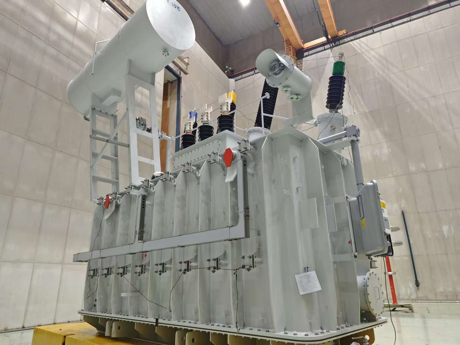
What Is the Required Voltage Rating and Voltage Regulation?
![]()
Selecting the correct voltage rating and understanding the transformer’s voltage regulation are fundamental to ensuring safe, efficient, and stable power delivery. These parameters directly influence the transformer’s compatibility with the system, its performance under varying load conditions, and its long-term operational reliability. Below is a clear, practical explanation tailored for power transformer applications.
Required Voltage Rating
The voltage rating defines the primary and secondary voltages a transformer is designed to handle. Choosing the correct rating ensures the transformer can interface seamlessly with both the upstream grid and downstream equipment.
1. Primary Voltage Rating
This depends on the source supply network.
Examples include:
- 6 kV / 10 kV (typical distribution levels)
- 33 kV / 35 kV (medium-voltage grids)
- 110 kV / 132 kV / 220 kV and higher (transmission-level)
The transformer must match the exact system voltage and any applicable tap changer adjustment range.
2. Secondary Voltage Rating
Determined by the load’s requirements.
Typical values include:
- 400/230 V for LV distribution
- 3.3 kV / 6.6 kV / 11 kV for industrial feeders
- Custom voltages for special machinery or renewable applications
The secondary voltage must be stable and appropriate for safe operation of downstream electrical equipment.
3. Insulation Level and BIL
Along with voltage class, insulation requirements such as BIL (Basic Insulation Level) must match system fault levels and switching surges to ensure safety.
Choosing incorrect voltage ratings can result in overheating, insulation failure, low efficiency, and unsafe operating conditions.
Voltage Regulation
Voltage regulation describes how much the output voltage changes between no-load and full-load conditions. It reflects both the transformer’s internal impedance and its ability to maintain stable output under varying load.
Definition
Voltage Regulation = ((V_no-load – V_full-load) / V_full-load) × 100%
A lower percentage indicates better voltage stability.
Typical Voltage Regulation Values
- Dry-type transformers: ~2%–6%
- Oil-immersed distribution transformers: ~1.5%–5%
- Power transformers (higher MVA): ~0.5%–2%
Values depend on winding design, core structure, and impedance.
Why Voltage Regulation Matters
- Ensures stable voltage for sensitive loads
- Prevents equipment malfunction during load fluctuations
- Improves power quality
- Reduces losses and enhances efficiency
- Supports renewables, EV chargers, and variable industrial loads
Influencing Factors
- Load type (linear vs non-linear)
- Transformer impedance
- Winding resistance and leakage reactance
- Load power factor
- Temperature and material characteristics
Summary
| Parameter | What It Determines | Why It’s Important |
|---|---|---|
| Voltage Rating | Compatibility with grid and load | Safe operation, correct insulation, system matching |
| Voltage Regulation | Output stability under load | Power quality, efficiency, protection of connected devices |
How Does the Transformer’s kVA/MVA Capacity Match the Load Demand?

Selecting the correct kVA/MVA capacity is one of the most critical steps in transformer specification. The transformer must handle all expected loads safely, efficiently, and without excessive heating. Undersizing leads to overload, accelerated aging, and premature failure; oversizing increases cost and reduces efficiency at light loads. Here is a clear, professional explanation tailored for power transformer applications.
1. Understanding Load Demand
The load connected to the transformer determines the minimum capacity. Load demand typically includes:
- Continuous load (base load)
- Peak load (short-duration maximum)
- Future expansion margin
- Starting currents (motors, compressors, pumps)
- Non-linear loads (VFDs, rectifiers, EV chargers)
A transformer must be able to withstand the maximum expected load plus a safe margin, without exceeding its temperature rise limits.
2. Basic Capacity Matching Formula
To determine required transformer size:
Required kVA = (Load Voltage × Load Current × √3) / 1000
For MVA:
Required MVA = (kVA / 1000)
However, this is only the starting point. Real-world selection requires additional factors.
3. Considering Load Profile
A transformer must match not just peak load but the entire operating profile:
A. Continuous Load
Transformers operate best when the load is around 40–70% of rated capacity.
B. Peak Load
Peak loads lasting seconds or minutes may be acceptable, depending on overload capability.
C. Daily and Seasonal Variations
Utilities, factories, and renewable sites require capacity tailored to patterns:
- Factories: High daytime peaks
- Hospitals: Stable, critical loads
- EV charging stations: Evening and night peaks
- Solar plants: Daytime peaks; zero nighttime load
Load diversity and simultaneity factor also adjust required kVA.
4. Overload Capability and Standards
Manufacturers design transformers according to standards such as:
- IEC 60076-7 (Loading Guide)
- IEEE C57.91
These define how long a transformer can overload without exceeding thermal limits. Properly sized units remain within safe operating temperatures.
5. Allowance for Future Growth
Most engineering designs include a 20–30% growth margin, especially in:
- Industrial expansions
- Commercial facilities
- Data centers
- Utility substations
- Renewable energy projects
This prevents expensive upgrades or early replacement.
6. Matching Capacity to Load Type
Different loads require different considerations:
A. Motor Loads
Motors draw 6–8× rated current during start-up. Transformers must have:
- Sufficient kVA
- Adequate impedance
- Thermal capability
B. Non-Linear Loads
Loads such as VFDs, UPS, and chargers cause:
- Harmonics
- Higher losses
- Heating in windings and core
Transformers for these loads may require K-factor ratings or derating.
C. Renewable Energy Loads
Wind and solar generators require:
- Precise MVA sizing
- Reverse power flow capability
- Harmonic tolerances
- Variable load support
D. Utility and Grid Transformers
These are often sized by:
- Load duration curves
- Short-circuit duty
- Regional load growth
- Power quality requirements
7. Impact of Temperature and Cooling
Transformer capacity depends on cooling class:
- AN/AF (Dry-type): Lower overload capability
- ONAN/ONAF/ODAF (Oil-immersed): Higher thermal margin
A hot environment reduces effective kVA rating unless designed with derating or enhanced cooling.
8. Summary Table
| Factor | Influence on Required kVA/MVA Capacity |
|---|---|
| Base load | Determines minimum transformer size |
| Peak load | Ensures short-term stability |
| Future expansion | Avoids early replacement |
| Load type (motor, EV, VFD) | May require oversizing or derating |
| Harmonics | Requires K-factor or derating |
| Temperature rise limits | Affects thermal capacity |
| Cooling method | Alters overload capacity |
| Standards (IEC/IEEE) | Defines safe loading capabilities |
What Efficiency and Loss Parameters Must Be Evaluated?
Evaluating efficiency and loss parameters is essential when selecting a power transformer because these factors directly influence energy consumption, operating costs, temperature rise, and long-term reliability. A transformer with lower losses not only saves money over its service life but also operates more safely and supports system stability. Below is a clear and expert explanation of the key loss components and efficiency metrics that must be assessed.
1. Core (No-Load) Losses
Core losses occur whenever the transformer is energized, regardless of load. They are primarily caused by the alternating magnetic field in the core.
A. Hysteresis Loss
- Depends on magnetic core material
- Reduced by using high-grade silicon steel or amorphous alloy
- Stable regardless of load level
B. Eddy Current Loss
- Caused by circulating currents in laminations
- Minimized through thin laminations and high-quality insulation coating
Importance:
Core losses dominate during low-load operation and influence the transformer’s efficiency in standby or lightly-loaded usage (common in utilities, renewables, commercial systems).
2. Copper (Load) Losses
Load losses occur due to current flowing in the windings. They increase with load and must be evaluated carefully.
A. I²R Losses
- Increases with square of load current
- Highly dependent on conductor size and material (copper vs aluminum)
B. Stray Losses
Caused by leakage flux inducing currents in:
- Structural parts
- Windings
- Tank walls
C. Additional Load Losses
From non-uniform current distribution, especially under harmonics.
Importance:
Load losses dominate at medium to high load, affecting efficiency during peak operation and determining heat generation.
3. Total Losses and Efficiency
Transformer efficiency is calculated based on both core and copper losses:
Efficiency = Output Power / (Output Power + Total Losses)
Typical efficiency ranges:
| Transformer Type | Rated Efficiency |
|---|---|
| Dry-Type (medium-voltage) | 97.0%–98.3% |
| Oil-Immersed (distribution) | 98.5%–99.2% |
| Large Power Transformers | 99.3%–99.75% |
Efficiency standards such as DOE, EU EcoDesign, and IEC 60076 define minimum acceptable limits.
4. Impedance and Voltage Regulation Loss Impacts
Transformer impedance affects:
- Voltage drop
- Fault current capability
- Load losses
Higher impedance reduces fault current but increases voltage drop and copper losses.
5. Harmonic Loss Evaluation
In systems with:
- VFDs
- UPS
- EV chargers
- Solar/wind inverters
- Data center loads
Harmonics cause additional heating and increase:
- Eddy current losses
- Stray losses
- Winding hot-spot temperature
A transformer may need:
- K-factor rating
- Derating
- Special winding design
6. Temperature Rise and Thermal Class
Losses directly influence internal temperature. Key evaluations:
- Winding hot-spot temperature
- Average temperature rise
- Insulation class (A, B, F, H)
- Cooling method (AN, AF, ONAN, ONAF)
Lower temperature rise means:
- Longer insulation life
- Higher reliability
- Better efficiency
7. Load Loss vs. No-Load Loss Optimization
Depending on application, optimization shifts:
Utility or Renewable Systems
- High no-load loss sensitivity
- Often oversized or lightly loaded
- Amorphous cores preferred
Industrial Facilities
- High load-loss sensitivity due to continuous operation
- Heavy-current copper optimization important
Summary Table
| Parameter | Why It Matters | Influenced By |
|---|---|---|
| Core Losses | Key for low-load efficiency | Core material, lamination thickness |
| Copper Losses | Defines high-load performance | Conductor size, temperature, harmonics |
| Stray Losses | Impacts heating & efficiency | Winding design, tank geometry |
| Efficiency | Determines lifetime cost | Total losses, voltage, load profile |
| Impedance | Affects VR & fault current | Winding geometry |
| Thermal Performance | Direct link to insulation life | Cooling class, load losses |
How Do Impedance and Short-Circuit Strength Affect System Reliability?
Impedance and short-circuit strength are two of the most important parameters in transformer design, and both directly determine how well the electrical system withstands faults, maintains stability, and protects downstream equipment. Choosing improper values can lead to dangerous fault currents, voltage instability, accelerated aging, or catastrophic failure. Below is a clear, expert-level breakdown of how these two factors influence overall system reliability.
1. Transformer Impedance and Its Impact on System Performance
Transformer impedance (Z%) determines the internal voltage drop and how much current will flow during a short-circuit event. It affects reliability in several key ways:
A. Fault Current Limitation
Lower impedance → higher fault current
Higher impedance → lower fault current
Example:
- A 6% impedance transformer produces ~16.7× rated current during a fault.
- An 8% impedance unit reduces fault current significantly, protecting cables, switchgear, and breakers.
Selecting the wrong impedance can overload protective devices or cause delayed tripping.
B. Voltage Regulation Under Load
Impedance influences how much voltage drops at full load:
- Low impedance → better voltage regulation
- High impedance → more voltage sag under load
A balance is required: good voltage stability without excessive fault current.
C. System Stability and Coordination
Proper impedance ensures:
- Smooth parallel operation
- Balanced load sharing
- Protection device coordination
- Reduced inrush and transient disturbances
Transformers with mismatched impedance cannot run in parallel safely.
2. Short-Circuit Strength and Mechanical Reliability
Short-circuit strength refers to the transformer’s ability to withstand the enormous mechanical forces generated by fault currents. These forces can reach tens of thousands of newtons, enough to deform or damage windings if not properly designed.
A. Axial and Radial Forces
During a fault:
- Radial forces try to compress or expand the windings
- Axial forces attempt to separate or collapse the coil structure
Only high-quality mechanical design prevents deformation, displacement, or insulation damage.
B. Thermal Stress During Fault Conditions
High fault currents cause rapid heating:
- Windings must resist thermal shock
- Insulation must withstand instant temperature rise
- Structural bracing must prevent vibration damage
Failing short-circuit strength → winding deformation → partial discharge → failure.
C. Compliance with IEC and IEEE Standards
Short-circuit withstand capability is verified under:
- IEC 60076-5
- IEEE C57.12.00 / C57.12.90
Transformers that do not pass these tests are unsafe for high-fault-level networks.
3. Combined Effect on System Reliability
| Parameter | Impact on Reliability | Risk if Incorrect |
|---|---|---|
| Impedance (%) | Controls fault current and voltage regulation | Overcurrent damage, unstable voltage, miscoordination |
| Short-Circuit Strength | Ensures windings survive mechanical forces | Deformation, insulation failure, total transformer failure |
| Thermal Stability | Maintains insulation life under stress | Rapid aging, higher failure rate |
| Protection Coordination | Ensures breakers/fuses operate timely | Equipment burnout, widespread outages |
Both parameters must be evaluated together—high fault levels require both proper impedance selection and certified short-circuit withstand capability.
4. Practical Engineering Guidelines
A. High-Fault Networks
- Choose higher impedance (e.g., 8%–10%).
- Ensure strong mechanical bracing for short-circuit strength.
B. Voltage-Sensitive Applications
- Lower impedance for better voltage regulation (5%–6%).
C. Parallel Operation
- Impedance must match within ±10%
- Ensure identical vector group and capacity ratios
D. Industrial Plants with Heavy Motor Loads
- Low impedance for motor starting voltage support
- High SC strength to survive high inrush currents
What Insulation Class and Thermal Performance Are Needed?
Selecting the correct insulation class and thermal performance level is essential to ensure that a transformer can operate safely under expected temperature conditions, withstand overloads, and maintain long service life. Insulation is one of the most critical components in both dry-type and oil-immersed transformers because thermal aging is the number-one cause of transformer failure. Here is a clear, expert explanation of how to determine the right insulation class and thermal requirements for your application.
1. Understanding Insulation Classes
Transformer insulation systems are classified by their maximum allowable temperature limits. The most common insulation classes include:
| Insulation Class | Max Winding Temperature (°C) | Typical Use |
|---|---|---|
| Class A | 105°C | Small dry-type, older equipment |
| Class B | 130°C | General-purpose dry-type |
| Class F | 155°C | Industrial dry-type, higher load environments |
| Class H | 180°C | Harsh environments, traction, marine |
| Oil-immersed (IEC 60076) | 98°C (hot spot) | Distribution & power transformers |
Dry-type transformers use Class B, F, or H insulation, while oil-immersed transformers follow a different thermal system governed by oil temperature rise and hot-spot limits.
2. How Thermal Limits Affect Transformer Lifespan
The life of a transformer’s insulation halves for every 6–8°C increase in hot-spot temperature. This means choosing the right class is essential for long-term reliability.
- A transformer running too hot ages rapidly, leading to insulation cracking, coil deformation, and partial discharge.
- A transformer with proper thermal design maintains dielectric strength and survives for 20–30+ years.
3. Temperature Rise Requirements
Temperature rise defines how much the transformer heats up above ambient temperature under rated load.
Typical values:
Dry-Type Transformers
- 80°C rise → High efficiency
- 115°C rise → Standard efficiency
- 150°C rise → Higher capacity in smaller footprint
Oil-Immersed Transformers
- 55°C rise → Premium efficiency
- 65°C rise → Standard efficiency
A lower temperature rise means lower losses, higher reliability, and longer insulation life.
4. Factors That Determine Needed Insulation Class
A. Operating Environment
The harsher the environment, the higher the insulation class typically required:
- High temperature areas → Class F or H
- Marine/offshore → High moisture resistance
- Mining, tunnels, metro → Fire resistance and Class H insulation
- Outdoor renewables → UV, dust, and humidity protection
B. Load Characteristics
- Heavy motor loads → Higher thermal stress
- EV chargers → High harmonic content → Increased heating
- Data centers → Continuous high load → Lower temperature rise preferred
C. Overload Requirements
Some applications require the transformer to withstand temporary overloads without insulation damage. Higher insulation classes provide more thermal headroom.
D. Installation Type
- Enclosed spaces → Reduced ventilation → Higher thermal class needed
- Forced-air cooling room → Lower insulation class acceptable
5. Matching Thermal Performance to Application
| Application | Recommended Insulation Class | Rationale |
|---|---|---|
| Commercial buildings | Class B or F | Moderate load, safe temperatures |
| Industrial plants | Class F | High duty cycle, heat tolerance |
| Metro, tunnels, marine | Class H | Harsh, hot, and safety-critical |
| Renewable energy substations | Class F or H | Outdoor, variable load |
| Data centers | Low temperature rise + high efficiency | Continuous heavy load |
| Oil-immersed grid transformers | Standard oil insulation system | High thermal stability |
6. Special Considerations for Dry-Type Transformers
Dry-type units require:
- High thermal class insulation
- Adequate ventilation or forced-air cooling
- Materials resistant to humidity and contamination
- Coil design optimized for hotspot reduction
- Epoxy or resin systems that withstand thermal cycling
Resin-rich and cast-resin systems differ in thermal behavior, so the manufacturer’s design quality is crucial.
7. Why Choosing the Right Insulation Class Matters
Proper insulation and thermal design ensure:
- Long equipment lifespan
- Lower energy losses
- Stable operation under peak load
- Resistance to thermal shock
- Reduced maintenance and failures
Underspecifying insulation leads to premature aging, overheating, failure, or safety risks—especially in dry-type installations exposed to harsh conditions.
Below is an original, in-depth explanation written in the same style and depth as your previous requests, with clear section headings but without using H3/H2 tags.
How Do Noise Level, Cooling Method, and Environmental Conditions Influence Transformer Selection?
Choosing the right transformer involves more than just voltage and capacity. Noise emissions, cooling method, and the surrounding environment directly affect long-term performance, regulatory compliance, installation costs, and overall safety. Understanding how these three factors interact allows buyers to specify a transformer that is not only technically correct but also optimized for real-world conditions.
1. Noise Level: A Critical Factor in Sensitive Installations
Transformers generate mechanical and electromagnetic noise from core magnetostriction, coil vibration, and cooling fans or pumps. In many applications, noise limits are strictly regulated or sensitive to human comfort.
Why Noise Level Matters
- Urban and residential areas require low-noise operation to comply with municipal regulations and avoid disturbance.
- Commercial buildings, hospitals, data centers, and schools demand quiet environments to maintain comfort and productivity.
- Underground facilities amplify noise, requiring even stricter limits.
How Noise Affects Transformer Choice
- Dry-type transformers are often quieter at small to medium ratings but may become noisy at higher capacities if not properly designed.
- Oil-immersed transformers with sealed tanks often offer lower noise levels for large power ratings.
- Low-noise designs (step-lap cores, vibration-damping supports, precision winding) may be required in premium installations.
- Fan-cooled units increase noise; if quiet operation is required, higher-efficiency natural-cooled transformers may be preferred.
In sensitive environments, buyers may need to select a transformer with certified low-noise ratings and consider extra acoustic insulation or enclosure design.
2. Cooling Method: Directly Connected to Efficiency, Lifespan, and Safety
Cooling defines how heat is removed from the transformer windings. Excess heat shortens insulation life and reduces efficiency, so choosing the right cooling system is essential.
Common Cooling Methods
Dry-Type Transformers:
- AN (Air Natural) – quiet, simple, ideal for indoor use
- AF (Air Forced) – increased capacity and cooling but adds noise and moving parts
Oil-Immersed Transformers:
- ONAN – natural convection, high reliability
- ONAF / ODAF / OFAF – forced cooling for higher power ratings
- K-class oil – for fire-sensitive environments
How Cooling Method Influences Selection
- Indoor applications (malls, high-rises, hospitals) often prefer dry-type AN cooling for safety and simplicity.
- High-power outdoor substations typically use oil-immersed ONAN/ONAF due to superior heat dissipation.
- Hot climates require more robust cooling—air-cooled units may be derated.
- Overload-prone systems may need forced-air or forced-oil cooling to maintain safe temperatures.
- Fire safety requirements (tunnels, offshore platforms) may necessitate dry-type or natural-ester-filled transformers.
Cooling strategy is not just a technical choice; it directly affects total cost of ownership, efficiency, and operational reliability.
3. Environmental Conditions: Shapes Material Choices and Design Requirements
Environmental conditions determine the transformer’s resilience, lifespan, and maintenance needs. Temperature, humidity, pollution, altitude, and risk of corrosion all must be considered.
Key Environmental Factors
- Ambient temperature affects the transformer's temperature rise and may require derating or higher-class insulation.
- Humidity and moisture can degrade insulation, especially in dry-type transformers without proper resin encapsulation.
- Pollution levels and corrosive atmospheres (chemical plants, coastal areas) accelerate corrosion and partial discharge risk.
- Altitude reduces air density and cooling effectiveness—units above 1,000 m often require derating.
- Dust and particulates can block ventilation paths in dry-type units, requiring filters or sealed enclosures.
- Seismic activity may require reinforced frames and bushings.
How Environmental Conditions Guide Transformer Selection
- Coastal and marine environments → corrosion-resistant coatings, sealed oil tanks, or cast resin dry-type transformers.
- High-dust or mining environments → totally enclosed dry-type designs to prevent contamination.
- High-altitude installations → derated units or enhanced cooling.
- Cold regions → oil with low pour point or heaters to prevent viscosity issues.
- Industrial sites with chemicals → epoxy-resin systems or special enclosures.
Environmental conditions are not optional factors—they determine the transformer’s survival and reliability over decades.
4. Bringing It All Together: Optimizing the Selection
A transformer that meets electrical specifications may still fail or perform poorly if noise, cooling, or environmental conditions are not matched to the real installation scenario.
Balanced Selection Approach
- Match noise level to regulatory and human requirements.
- Choose cooling method based on load profile, power rating, and heat management needs.
- Adapt design and insulation to environmental stress factors.
- Evaluate the long-term cost implications of cooling efficiency, fan operation, enclosure design, and derating.
- Ensure standards compliance (IEC 60076, IEEE C57) for safety and reliability.
The best transformer is one that delivers performance with minimal maintenance, long lifespan, and compatibility with its operating environment—not just the lowest initial price.
Conclusion
Critical transformer performance parameters—such as voltage ratings, capacity, efficiency, impedance, insulation class, cooling method, and environmental suitability—play a decisive role in ensuring safe and efficient operation. Evaluating these criteria helps ensure that the transformer can withstand expected loads, operate safely under varying conditions, and deliver long-term reliability. A transformer chosen with careful attention to these performance metrics not only improves system stability but also reduces energy loss and maintenance costs throughout its service life.
FAQ
Q1: What are the most important electrical performance parameters to evaluate in a power transformer?
When selecting a power transformer, the most fundamental electrical performance parameters include rated power (kVA/MVA), rated voltage, impedance, frequency, and vector group. Rated power determines how much load the transformer can reliably handle. Voltage rating and turns ratio must match the system requirements on both primary and secondary sides to ensure safe and efficient operation.
Impedance is critical because it affects short-circuit strength, voltage regulation, and transformer protection coordination. Lower impedance improves regulation but increases fault current, while higher impedance reduces fault current but may impact voltage stability. Frequency (typically 50/60 Hz) must match the grid standard. The vector group defines phase shift and connection type—important for parallel operation, harmonics mitigation, and system grounding. These parameters collectively determine how well the transformer integrates into the grid.
Q2: Why are efficiency and losses essential when choosing a transformer?
Efficiency is one of the biggest contributors to long-term operating cost. Power transformers have two types of losses:
No-load losses (core losses) – constant and influenced by the steel material, core design, and flux density
Load losses (winding losses) – vary with load and influenced by conductor size, winding design, and temperature rise
Selecting a transformer with lower losses significantly reduces energy consumption over its lifespan, which can exceed 30–40 years. High-efficiency units use premium silicon steel or amorphous metal cores, optimized magnetic flux patterns, and low-resistance windings. With energy regulations becoming stricter (IEC, DOE, EU Ecodesign), choosing a transformer with certified low losses is essential for economic and environmental performance.
Q3: How do cooling method and temperature rise impact performance?
Cooling methods like ONAN, ONAF, OFAF, OFWF, AN, AF directly affect power handling, reliability, and lifespan. Efficient cooling allows the transformer to operate without overheating, increases overload capability, and reduces thermal stress.
Temperature rise is a key parameter—lower temperature rise (e.g., 55°C vs. 65°C) generally equals longer insulation life. High-temperature insulation classes (A, B, F, H) determine how well a transformer can handle thermal loading. Cooling and thermal design dictate how the transformer performs under peak load, harmonics, and ambient temperature variations.
Q4: Why is insulation level and BIL (Basic Insulation Level) important?
Insulation strength is critical for withstanding electrical stress during lightning strikes, switching surges, and grid disturbances. BIL defines the ability of the transformer to handle overvoltage impulses without breakdown. A transformer with inadequate BIL risks insulation failure, leading to catastrophic outages.
Insulation materials (mineral oil, ester oil, epoxy resin, cellulose, NOMEX) also influence fire safety, thermal endurance, and environmental compliance. Selecting the correct insulation class and BIL ensures long-term safety and grid reliability.
Q5: What mechanical and structural parameters should be considered?
Mechanical strength is crucial because transformers endure short-circuit forces, vibration, and transportation stress. Important mechanical parameters include:
Short-circuit withstand capability
Core clamping and structural rigidity
Winding mechanical strength
Vibration resistance
Seismic design requirements (for earthquake-prone regions)
Transformers built with strong structural features show better long-term reliability and are less prone to deformation or internal faults during high-stress events.
References
IEC 60076 – Power Transformer Standards — https://www.iec.ch
IEEE C57 Transformer Performance Guidelines — https://ieeexplore.ieee.org
Schneider Electric Transformer Engineering Guide — https://www.se.com
NEMA TR1 Transformer Efficiency Standards — https://www.nema.org
Doble Engineering – Transformer Testing and Performance — https://www.doble.com
EPRI Transformer Reliability Studies — https://www.epri.com

