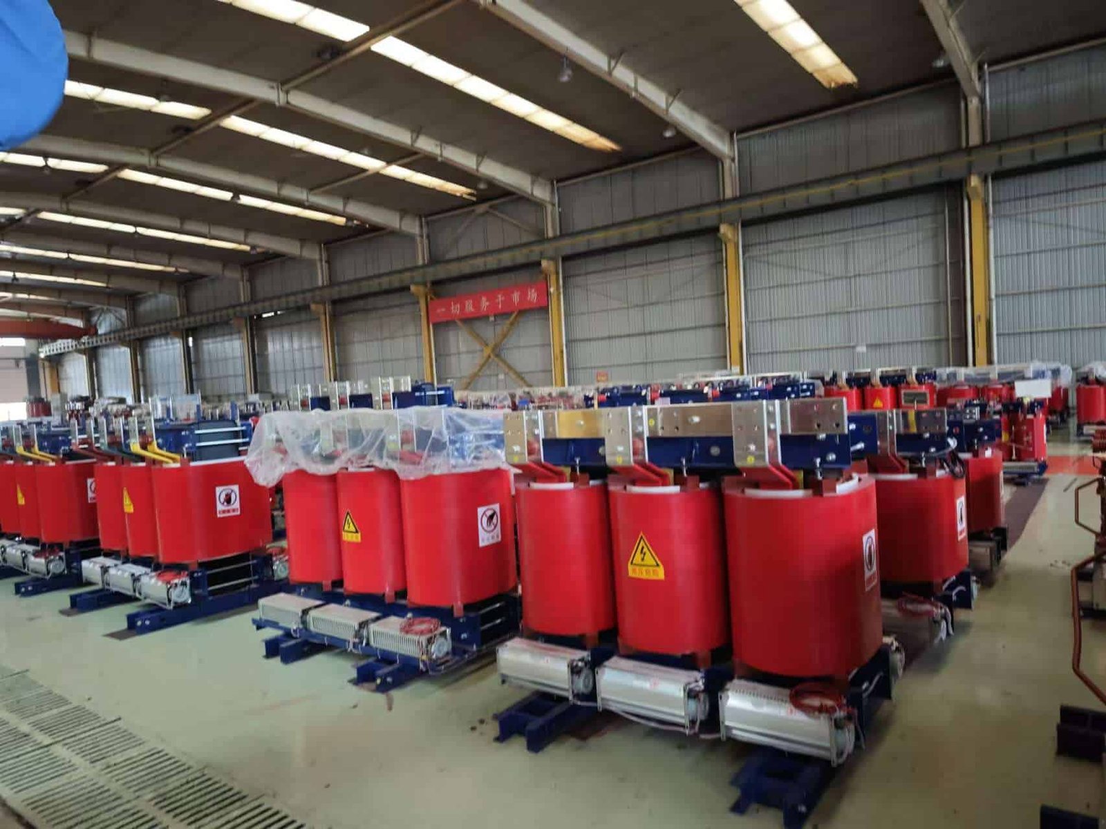
Dry-type transformers rely on air and solid insulation systems rather than liquid cooling media, making thermal management a critical aspect of their design. Effective cooling ensures safe operating temperatures, prevents insulation degradation, and maintains efficiency under varying load conditions. Understanding the cooling methods used in dry-type transformers helps engineers and users select the right configuration for reliability, performance, and installation environment.
What Is the Purpose of Cooling in Dry-Type Transformers?
Dry-type transformers, like all transformers, generate heat during operation due to electrical losses in their windings and magnetic core. Unlike oil-immersed transformers, they do not use liquid insulation for heat removal. Instead, they rely on air and solid insulation systems (such as cast resin or VPI insulation).
The purpose of cooling in dry-type transformers is to remove internally generated heat, control operating temperature, prevent insulation aging, maintain electrical performance, and ensure safe and reliable long-term operation.
Without proper cooling, temperature rise would quickly reduce transformer life and potentially cause failure.
1. Removal of Copper (Load) Loss Heat
When current flows through windings, resistive losses (I²R losses) generate heat.
Cooling ensures:
- Heat is transferred away from conductors
- Winding temperature stays within insulation limits
- Overheating is prevented under rated load
Load losses increase with current, so effective cooling is critical during high-demand periods.
2. Dissipation of Core (No-Load) Loss Heat
Even when no load is connected, the magnetic core produces:
- Hysteresis losses
- Eddy current losses
These generate continuous heat. Cooling maintains safe core temperature during both no-load and load conditions.
3. Protection of Insulation System
Insulation life is highly temperature-dependent.
As a general rule:
- Insulation aging rate roughly doubles for every 6–8°C increase in temperature
Cooling:
- Keeps winding temperature within its thermal class (e.g., Class F or Class H)
- Prevents premature insulation degradation
- Extends transformer service life
Temperature control directly impacts lifespan.
4. Prevention of Hot Spots
Hot spots are localized areas of elevated temperature within windings.
If not controlled, they can:
- Accelerate insulation breakdown
- Cause partial discharge
- Lead to thermal runaway
Proper airflow design and heat dissipation reduce temperature gradients and limit hot spot formation.
5. Maintenance of Electrical Performance
Electrical characteristics depend on temperature.
High temperature can:
- Increase winding resistance
- Reduce efficiency
- Affect voltage regulation
Cooling helps maintain stable electrical parameters under varying load conditions.
6. Support for Rated Power Output
Transformer power rating is limited by allowable temperature rise.
Effective cooling allows:
- Operation at full rated capacity
- Controlled overload capability (for short durations)
- Compliance with temperature rise standards
Without adequate cooling, rated output would need to be reduced.
7. Prevention of Thermal Stress and Mechanical Damage
Repeated heating and cooling cycles cause:
- Expansion and contraction of conductors
- Mechanical stress in insulation
- Potential cracking or fatigue
Cooling systems help maintain controlled temperature variation, reducing mechanical stress over time.
8. Fire Safety Considerations
Although dry-type transformers eliminate oil fire risk, excessive overheating can still:
- Damage insulation
- Produce smoke
- Create safety hazards
Cooling reduces the risk of temperature-related safety issues.
9. Cooling Methods in Dry-Type Transformers
Dry-type transformers typically use:
Air Natural (AN)
- Natural air circulation
- No fans
- Simpler design
Air Forced (AF)
- Fans increase airflow
- Improves heat removal
- Allows higher load capacity
The cooling method directly determines allowable temperature rise and power rating.
10. Ensuring Compliance with Standards
Transformer standards specify:
- Maximum temperature rise
- Thermal class limits
- Overload capability
Cooling systems ensure compliance with these performance requirements.
How Does Natural Air Cooling (AN) Work in Dry-Type Transformers?
Natural Air cooling (AN), sometimes called self-cooled, is the simplest cooling method used in dry-type transformers. It relies entirely on natural air circulation—without fans or pumps—to remove heat generated inside the transformer.
In AN cooling, heat produced in the windings and core is transferred to surrounding air through natural convection and radiation, with warm air rising and cooler air entering to maintain continuous airflow.
1. Heat Generation Inside the Transformer
Dry-type transformers generate heat from:
- Copper (I²R) losses in windings
- Core (iron) losses due to magnetization
This heat raises the temperature of the windings and magnetic core.
2. Heat Transfer from Windings to Surface
In cast resin or VPI transformers:
- Heat moves by conduction from copper conductors
- It passes through insulation materials
- It reaches the outer surface of the winding
The outer surface becomes warmer than the surrounding air.
3. Natural Convection Process
Natural air cooling works based on basic physics:
- Air near the hot surface heats up
- Heated air becomes less dense
- Warm air rises upward
- Cooler ambient air flows in from below
- The cycle repeats continuously
This vertical airflow is called natural convection.
No mechanical assistance is required.
4. Role of Transformer Design
Dry-type transformers designed for AN cooling include:
- Vertical ventilation ducts between windings
- Open air passages
- Adequate spacing for airflow
- Elevated mounting to allow bottom air entry
These structural features encourage upward air movement.
5. Heat Dissipation to the Environment
Heat is removed through two mechanisms:
Convection
- Moving air carries heat away
Radiation
- Heat radiates from hot surfaces to the surroundings
Although radiation contributes, convection is the dominant mechanism.
6. Temperature Rise Limitation
The transformer’s rated capacity under AN cooling is determined by:
- Allowable insulation temperature class (e.g., Class F, Class H)
- Ambient temperature (commonly 40°C standard reference)
- Designed temperature rise limits
If heat cannot be removed quickly enough, temperature rise increases and limits load capacity.
7. No Moving Parts
Because AN cooling uses no fans:
- There are no mechanical components
- Maintenance requirements are low
- Noise is minimal
- Reliability is high
This makes AN systems simple and robust.
8. Advantages of AN Cooling
- Simple design
- High reliability
- Low maintenance
- No auxiliary power consumption
- Quiet operation
It is ideal for:
- Indoor installations
- Commercial buildings
- Hospitals
- Light industrial facilities
9. Limitations of AN Cooling
Natural convection has limited heat removal capacity.
Compared to forced air cooling:
- Lower maximum power rating
- Reduced overload capability
- Larger transformer size for same kVA
When higher capacity is required, fans may be added (AF cooling).
10. AN vs AF Comparison
| Aspect | AN (Air Natural) | AF (Air Forced) |
|---|---|---|
| Air movement | Natural convection | Fan-assisted |
| Moving parts | None | Fans |
| Maintenance | Minimal | Moderate |
| Cooling capacity | Lower | Higher |
| Noise level | Low | Higher |
| Overload capability | Limited | Improved |
What Is Forced Air Cooling (AF) and When Is It Used?
As electrical loads grow and power density increases, dry-type transformers operating under natural air (AN) cooling may reach their thermal limits. When temperature rise approaches insulation class limits, continued operation under higher loads can accelerate insulation aging, reduce efficiency, and compromise reliability. This becomes especially critical in commercial buildings, industrial plants, data centers, and renewable energy systems where load variability is high and downtime is unacceptable. The solution is not always a larger transformer—it is often smarter thermal management. This is where Forced Air cooling (AF) plays a decisive role.
Forced Air cooling (AF) is a transformer cooling method that uses electrically powered fans to actively increase airflow across windings and core surfaces, enhancing heat dissipation and allowing the transformer to operate at higher load levels or improved thermal margins compared to natural air (AN) cooling. It is typically used when higher capacity, temporary overload capability, or enhanced temperature control is required.
Understanding how AF cooling works and when to apply it can significantly improve transformer utilization, lifecycle performance, and overall system economics. Let us examine the technical details from a practical manufacturing and application perspective.
1. How Forced Air Cooling (AF) Works
In dry-type transformers, heat is generated primarily by:
- Copper (load) losses in the windings
- Core (no-load) losses in the magnetic circuit
Under AN cooling, heat removal depends solely on natural convection. In AF cooling, fans are installed—usually at the bottom or sides of the transformer enclosure—to force ambient air through ventilation ducts.
The process works as follows:
- Fans draw cooler ambient air into the transformer
- Air is directed through vertical and radial cooling channels
- Accelerated airflow absorbs heat from winding and core surfaces
- Heated air is expelled through top vents
The key improvement lies in increasing the air velocity. Since convective heat transfer is proportional to airflow rate, forced convection dramatically improves heat dissipation.
The heat transfer relationship can be simplified as:
Q = h × A × ΔT
Where:
Q = heat dissipated
h = heat transfer coefficient
A = surface area
ΔT = temperature difference
AF cooling increases the heat transfer coefficient (h), allowing more heat removal at the same temperature rise.
2. When Is AF Cooling Used?
Forced Air cooling is typically used in the following scenarios:
- When higher rated capacity is required without increasing transformer size
- When load demand fluctuates and periodic overload capability is needed
- In installations where ambient temperature is high
- In compact indoor spaces with limited natural ventilation
- When optimizing lifecycle cost per kVA
In practice, many dry-type transformers are designed with dual ratings:
Example:
1000 kVA (AN) / 1300 kVA (AF)
This means the transformer operates at 1000 kVA under natural cooling and can safely deliver 1300 kVA when fans are activated.
3. AN vs AF Cooling Performance Comparison
| Parameter | AN (Air Natural) | AF (Air Forced) |
|---|---|---|
| Air Movement | Natural convection | Fan-assisted |
| Cooling Capacity | Standard | 20–40% higher |
| Power Density | Lower | Higher |
| Overload Capability | Limited | Improved |
| Auxiliary Power | None | Required for fans |
| Noise Level | Low | Moderate |
| Maintenance | Minimal | Periodic fan checks |
In most dry-type designs, AF cooling increases capacity by 20% to 40% without enlarging core or winding size.
4. Technical Impact on Transformer Performance
AF cooling provides several operational advantages:
Reduced operating temperature
Lower average winding temperature improves insulation life.Extended overload capability
Temporary peak loads can be handled safely.Improved thermal distribution
Reduced hot spots within windings.Better voltage regulation under load
Lower temperature means lower resistance rise.
However, AF cooling does not reduce internal losses—it enhances heat removal. Losses remain proportional to load and core design.
5. Thermal Class and Insulation Considerations
Dry-type transformers commonly use:
- Class F insulation (155°C limit)
- Class H insulation (180°C limit)
AF cooling helps maintain temperature well below these limits during peak operation.
For example:
| Condition | Winding Temp (AN) | Winding Temp (AF) |
|---|---|---|
| 100% Load | 120°C | 100°C |
| 120% Load | Exceeds limit | 125°C (acceptable short-term) |
Maintaining lower temperature significantly extends insulation life, as thermal aging approximately doubles for every 6–8°C rise.
6. Control Systems for AF Cooling
Modern AF systems include:
- Temperature sensors (PT100 or thermal sensors)
- Automatic fan control panels
- Multi-stage fan activation
- Alarm and trip protection
Fans typically activate when winding temperature reaches a preset threshold (for example 110°C) and shut off when temperature drops.
This ensures:
- Energy-efficient operation
- Reduced fan wear
- Optimized thermal control
7. Applications Where AF Cooling Is Common
AF cooling is widely used in:
- Data centers
- Hospitals
- Airports
- High-rise buildings
- Industrial manufacturing plants
- Renewable energy plants (solar/wind substations)
In these environments, load variability and reliability demands justify the enhanced cooling capability.
8. Economic Considerations
From a project perspective, AF cooling allows:
- Smaller transformer footprint
- Reduced capital cost compared to larger AN-only unit
- Improved kVA per square meter
- Higher asset utilization
Instead of purchasing a 1500 kVA AN transformer, a 1000/1300 kVA AN/AF transformer may be sufficient.
This improves return on investment while maintaining safety margins.
9. Limitations of AF Cooling
Despite its benefits, AF cooling has considerations:
- Fans require auxiliary power
- Moving parts increase maintenance
- Additional noise is generated
- Failure of fans reduces available capacity
Therefore, AF systems should always include redundancy or alarm protection.
10. Reliability and Lifecycle Impact
When properly designed:
- AF cooling reduces average thermal stress
- Extends insulation lifespan
- Improves load flexibility
- Supports smart energy management
However, fan inspection and cleaning must be part of preventive maintenance schedules.
How Do Ventilation Design and Enclosures Influence Cooling Performance?
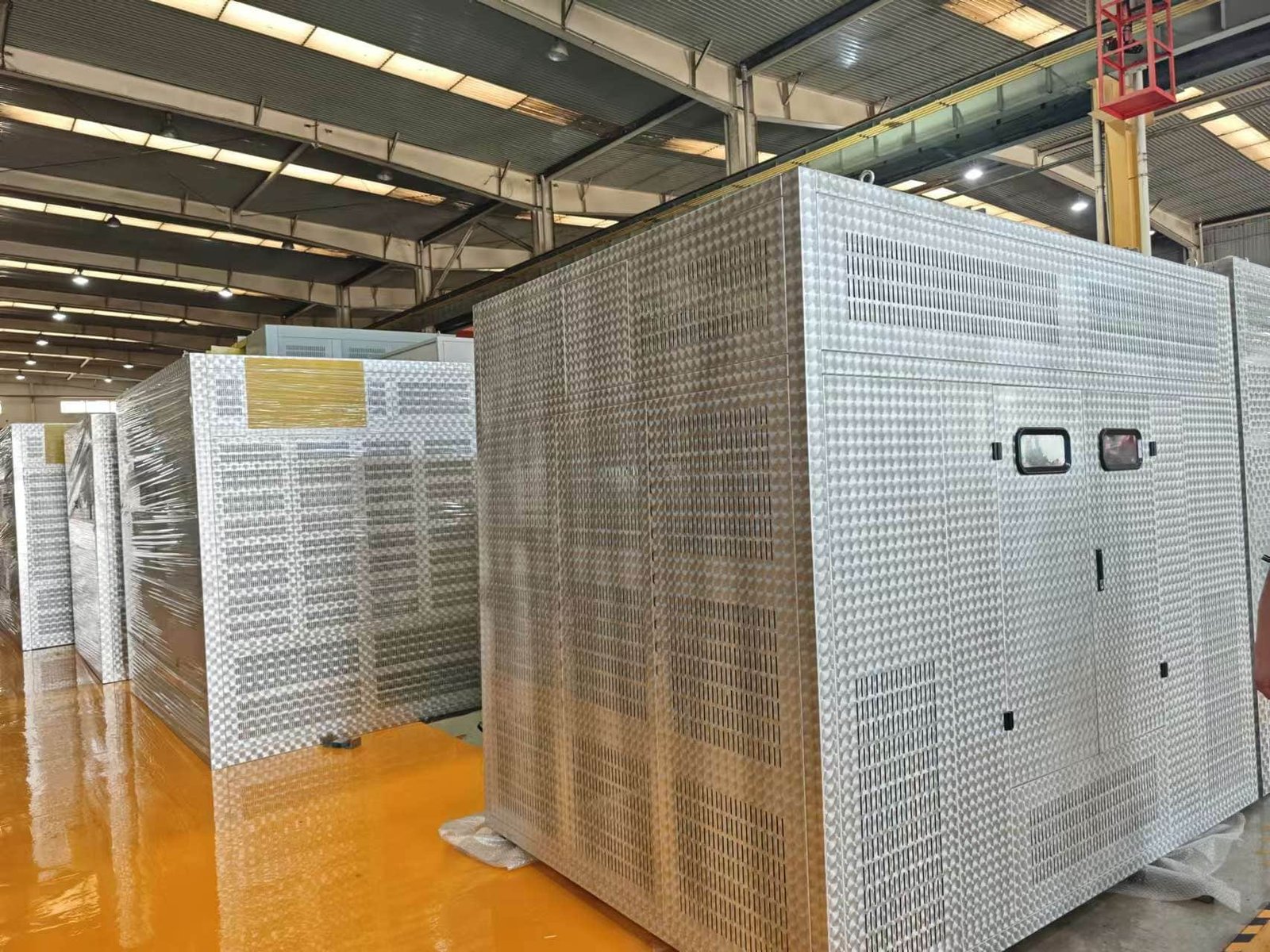
In real-world transformer installations, many cooling failures are not caused by poor core or winding design—they are caused by inadequate ventilation and poorly engineered enclosures. Even a high-efficiency dry-type transformer can overheat if airflow is restricted, recirculated, or trapped inside a confined space. The consequences include elevated winding temperatures, accelerated insulation aging, reduced load capacity, nuisance tripping, and shortened equipment lifespan. As a manufacturer and system designer, I have seen numerous cases where improper enclosure configuration increased operating temperature by 10–20°C, cutting insulation life in half. The solution is not simply adding fans—it is optimizing ventilation pathways and enclosure architecture from the beginning.
Ventilation design and enclosure configuration directly determine how effectively heat is removed from a transformer by controlling airflow direction, air exchange rate, heat dissipation area, and ambient temperature interaction. Properly engineered ventilation systems prevent heat recirculation, reduce hot spots, maintain insulation temperature limits, and ensure the transformer operates at its rated capacity safely and efficiently.
Understanding how airflow behaves inside transformer rooms and enclosures is essential to achieving reliable cooling performance. Let us analyze this systematically.
Proper cooling performance depends on the balance between heat generation and heat removal. In dry-type transformers, cooling is achieved primarily through air convection. Whether using Natural Air (AN) or Forced Air (AF), the surrounding enclosure must allow sufficient intake of cool air and discharge of hot air without obstruction. If airflow paths are blocked or poorly designed, the transformer essentially operates in a heat trap.
1. Fundamentals of Ventilation in Transformer Cooling
The cooling mechanism depends on three factors:
- Air volume (CFM or m³/h)
- Air velocity through winding ducts
- Temperature difference between intake and exhaust air
If the enclosure restricts airflow, the heat transfer coefficient decreases, leading to higher winding temperature rise.
The simplified heat removal equation:
Q = m × Cp × ΔT
Where:
Q = heat removed (W)
m = mass flow rate of air
Cp = specific heat capacity of air
ΔT = temperature rise of air
Ventilation design directly influences the mass flow rate (m). Poor ventilation reduces m, limiting heat removal.
2. Types of Transformer Enclosures and Their Impact
Transformer enclosures are typically classified as:
- Open type (IP00)
- Ventilated enclosure (IP20–IP23)
- Weatherproof enclosure (IP33–IP54)
- Soundproof or acoustic enclosure
Each has different airflow behavior.
| Enclosure Type | Airflow Freedom | Cooling Efficiency | Application |
|---|---|---|---|
| Open Type | Maximum | Highest | Indoor electrical rooms |
| Ventilated | Controlled natural flow | High | Commercial buildings |
| Weatherproof | Limited, filtered | Moderate | Outdoor installations |
| Acoustic | Restricted by insulation panels | Reduced | Noise-sensitive areas |
Acoustic enclosures, for example, often include sound-absorbing materials that partially block airflow. Without engineered air channels, cooling performance can drop significantly.
3. Air Inlet and Outlet Positioning
Correct positioning is critical.
Best practice:
- Air inlets at lower front or side panels
- Air outlets at upper rear or top
- Vertical airflow alignment with winding ducts
Improper positioning causes:
- Short-circuit airflow (air enters and exits without cooling windings)
- Recirculation of hot air
- Uneven temperature distribution
In many field retrofits, simply relocating louvers improved temperature performance by 8–12°C.
4. Avoiding Heat Recirculation
One of the most common cooling failures is hot air recirculation.
If exhaust air re-enters the intake area:
- Ambient temperature around transformer rises
- Cooling efficiency drops
- AF fans operate continuously
- Overtemperature alarms occur
To prevent this:
- Maintain physical separation between intake and exhaust
- Use directional baffles
- Provide adequate room ventilation
Recommended minimum clearance distances:
| Location | Minimum Clearance |
|---|---|
| Side walls | 300–800 mm |
| Front access | 1000 mm |
| Top clearance | 500–1000 mm |
5. Role of Room Ventilation in Indoor Installations
Transformer rooms must support enclosure ventilation.
Key considerations:
- Total heat load calculation (kW of losses)
- Required air exchange rate
- Ambient temperature control
- Mechanical exhaust systems if needed
Example:
A 2000 kVA dry-type transformer with total losses of 20 kW requires sufficient airflow to remove 20,000 W of heat continuously.
If room ventilation is insufficient, internal ambient temperature may rise from 35°C to 50°C, reducing available load capacity.
6. Influence of IP Rating on Cooling
Higher IP ratings provide better protection against dust and water but restrict airflow.
| IP Rating | Protection Level | Cooling Impact |
|---|---|---|
| IP00 | No protection | Maximum cooling |
| IP23 | Protected from solid objects | Slight reduction |
| IP44 | Splash resistant | Moderate restriction |
| IP54 | Dust protected | Reduced airflow |
There is always a trade-off between environmental protection and cooling performance. For dusty environments, filtered ventilation panels are used, but filters require maintenance to avoid airflow blockage.
7. Forced Air Systems and Enclosure Design
In AF cooling systems:
- Fans must be sized correctly
- Airflow must be evenly distributed
- Duct geometry must prevent dead zones
Poor enclosure geometry can cause:
- Uneven airflow
- Local hot spots
- Inefficient fan operation
Modern designs use airflow simulations (CFD analysis) to optimize enclosure performance before manufacturing.
8. Thermal Gradients and Hot Spots
Ventilation influences temperature uniformity.
Without proper airflow:
- Upper winding layers may exceed thermal class
- Core top sections overheat
- Insulation aging accelerates locally
A 10°C increase can reduce insulation life by nearly 50% based on Arrhenius thermal aging principles.
9. Outdoor Enclosure Considerations
Outdoor installations introduce additional factors:
- Solar radiation
- Wind direction
- Ambient temperature extremes
- Rain protection
Light-colored coatings and double-roof structures reduce solar heat absorption.
Ventilation louvers must be angled to prevent water ingress while maintaining airflow.
10. Best Practices for Optimal Cooling Performance
From engineering and field experience, I recommend:
- Perform detailed heat load calculation during design
- Ensure proper intake and exhaust positioning
- Avoid recirculation pathways
- Provide adequate room ventilation
- Use CFD analysis for large transformers
- Schedule filter cleaning maintenance
- Maintain clearance around enclosure
11. Practical Case Example
In a data center project, a 2500 kVA transformer experienced frequent temperature alarms. Investigation revealed:
- Exhaust louvers too close to intake
- Room exhaust fan undersized
- Top clearance only 200 mm
After redesigning ventilation layout:
- Winding temperature dropped by 14°C
- AF fans operated 40% less time
- Load capacity stabilized at rated level
No transformer replacement was needed—only ventilation correction.
What Role Do Insulation Materials Play in Heat Dissipation?
In transformers, insulation is primarily designed to withstand electrical stress, but it also plays a critical and often overlooked role in thermal performance. Since windings generate heat continuously due to copper (I²R) losses, that heat must pass through layers of insulation before reaching the cooling medium (air or oil). If insulation materials trap heat or restrict thermal flow, winding temperatures rise—accelerating aging and reducing service life.
Insulation materials influence heat dissipation by controlling thermal conductivity, facilitating or restricting heat transfer paths, maintaining dielectric strength at elevated temperatures, and preserving structural stability under thermal cycling.
Understanding this dual electrical-thermal function is essential for optimizing transformer reliability and efficiency.
1. Insulation as a Thermal Barrier and Thermal Conductor
All insulation materials have a property called thermal conductivity (k), which determines how easily heat passes through them.
- High thermal conductivity → better heat transfer
- Low thermal conductivity → heat retention
Heat transfer through insulation follows Fourier’s Law:
Q = k × A × (ΔT / d)
Where:
Q = heat flow
k = thermal conductivity
A = area
ΔT = temperature difference
d = insulation thickness
Thicker insulation (higher d) reduces heat flow unless compensated by higher thermal conductivity.
2. Balancing Electrical Strength and Thermal Conductivity
There is always a trade-off:
- Excellent electrical insulation materials often have low thermal conductivity.
- Good thermal conductors are often electrically conductive (which cannot be used directly in windings).
Therefore, transformer insulation systems are engineered to balance:
- Dielectric strength
- Thermal conductivity
- Mechanical strength
- Aging resistance
For example:
| Material | Electrical Strength | Thermal Conductivity | Application |
|---|---|---|---|
| Kraft paper | High | Moderate | Oil-immersed windings |
| Epoxy resin | Very high | Low–moderate | Cast resin transformers |
| Nomex (aramid paper) | Very high | Moderate | High-temperature insulation |
| Pressboard | High | Moderate | Spacers and barriers |
3. Role in Dry-Type Transformers
In dry-type transformers, heat must move from copper conductors → through insulation → into surrounding air.
Common insulation systems:
- Cast resin (epoxy encapsulation)
- VPI (Vacuum Pressure Impregnation) with varnish
Cast resin:
- Completely encapsulates windings
- Provides strong dielectric and mechanical protection
- Slightly reduces natural heat dissipation due to lower thermal conductivity
VPI systems:
- Thin resin coating
- Better airflow exposure
- Improved convective heat transfer
Thus, insulation selection directly affects cooling efficiency.
4. Role in Oil-Immersed Transformers
In oil-filled transformers, insulation materials work together with oil to transfer heat.
Heat path:
Copper → paper insulation → transformer oil → tank wall → ambient air
Oil has good thermal conductivity and circulates naturally (or forcibly), helping remove heat from windings.
Paper insulation must:
- Withstand hot oil exposure
- Maintain dielectric integrity
- Allow oil penetration for cooling
Proper oil impregnation improves thermal contact and reduces hot spots.
5. Impact on Hot Spot Temperature
The hottest point in a transformer is typically inside the winding.
Insulation affects:
- Thermal gradient between conductor and oil/air
- Localized heat buildup
- Temperature distribution uniformity
Poor thermal conduction leads to:
- Higher hot spot temperature
- Accelerated insulation aging
- Reduced transformer lifespan
A 6–8°C increase in hot spot temperature can halve insulation life.
6. Thermal Class and Heat Tolerance
Insulation materials are classified by thermal endurance:
| Thermal Class | Maximum Temperature |
|---|---|
| Class A | 105°C |
| Class F | 155°C |
| Class H | 180°C |
Higher-class materials allow:
- Higher operating temperature
- Greater overload capacity
- Improved lifespan under high stress
However, operating continuously near maximum class limit still accelerates aging.
7. Mechanical Stability Under Thermal Cycling
Transformers heat and cool daily due to load variations.
Insulation materials must:
- Expand and contract without cracking
- Maintain adhesion to conductors
- Resist vibration stress
Cracked insulation reduces both electrical reliability and heat transfer efficiency.
Resin systems, for example, must be formulated to avoid microcracking under thermal expansion mismatch between copper and insulation.
8. Influence on Cooling Method Selection
Insulation design impacts cooling configuration:
- Thick resin layers may require forced air cooling
- High-temperature insulation may reduce need for active cooling
- Oil-compatible insulation allows natural oil convection
Therefore, insulation choice is not independent—it affects overall cooling strategy.
9. Aging and Thermal Degradation
Over time, insulation degrades due to:
- Thermal oxidation
- Moisture
- Electrical stress
- Mechanical stress
Degraded insulation:
- Loses dielectric strength
- Develops cracks
- Impairs heat transfer
In oil transformers, insulation aging is monitored by dissolved gas analysis (DGA) and furan content testing.
10. Modern Innovations in Thermal Performance
Recent advancements include:
- Nano-filled epoxy resins with improved thermal conductivity
- High-temperature aramid insulation systems
- Improved oil-paper compatibility materials
- Enhanced resin formulations with reduced thermal resistance
These innovations improve heat transfer while maintaining dielectric strength.
How Is the Appropriate Cooling Method Selected for Different Applications?
Selecting the correct transformer cooling method is not simply a technical preference—it directly affects performance, lifespan, reliability, footprint, noise level, safety, and total lifecycle cost. An undersized cooling system leads to overheating and accelerated insulation aging. An oversized or overly complex cooling system increases capital cost and maintenance requirements.
The appropriate cooling method is selected by evaluating load profile, transformer rating, installation environment, ambient temperature, space constraints, safety requirements, reliability targets, and economic considerations.
Below is a structured engineering approach to selecting the optimal cooling configuration.
1. Determine Transformer Type (Dry vs. Oil-Immersed)
Cooling options depend first on transformer construction.
Dry-Type Transformers
Common cooling methods:
- AN – Air Natural
- AF – Air Forced (fan-assisted)
Typical applications:
- Commercial buildings
- Hospitals
- Data centers
- Indoor industrial facilities
Oil-Immersed Transformers
Common cooling methods:
- ONAN – Oil Natural Air Natural
- ONAF – Oil Natural Air Forced
- OFAF – Oil Forced Air Forced
- OFWF – Oil Forced Water Forced
Typical applications:
- Utility substations
- Heavy industrial plants
- Renewable energy farms
- Transmission systems
Transformer type narrows the cooling options.
2. Evaluate Transformer Rating and Load Profile
Cooling selection depends heavily on:
- Rated capacity (kVA or MVA)
- Continuous vs. intermittent loading
- Expected overload conditions
General guideline:
| Rating Range | Typical Cooling |
|---|---|
| Up to ~2.5 MVA (dry) | AN or AN/AF |
| Up to ~10–30 MVA | ONAN or ONAF |
| Above ~30 MVA | OFAF or OFWF |
If load is steady and predictable → Natural cooling may be sufficient.
If load fluctuates or peaks occur → Forced cooling provides flexibility.
3. Consider Ambient Temperature Conditions
Ambient temperature directly affects cooling efficiency.
Key considerations:
- Maximum ambient temperature
- Seasonal variations
- Indoor vs. outdoor installation
High ambient temperature environments (e.g., >40°C) may require:
- Larger radiators
- Fan-assisted cooling
- Oil forced systems
- Derating if cooling is limited
Cooling systems must maintain winding temperature within insulation class limits under worst-case ambient conditions.
4. Analyze Installation Environment
The physical installation location strongly influences cooling method.
Indoor Installations
- Space constraints
- Limited ventilation
- Noise sensitivity
Dry-type AN or AF is common.
Oil-immersed units may require ventilation ducts.
Outdoor Installations
- Sun exposure
- Wind
- Dust and moisture
ONAN is often sufficient for medium ratings.
High-power units may require ONAF or OFAF.
Confined Spaces
- Underground vaults
- Compact substations
Forced cooling may be necessary to compensate for limited airflow.
5. Assess Space and Footprint Constraints
Cooling systems influence transformer size.
Natural cooling requires:
- Larger radiator surface area
- Larger tank dimensions
Forced cooling allows:
- Smaller footprint
- Higher power density
Urban or industrial sites with limited space often use forced cooling to maximize kVA per square meter.
6. Evaluate Noise Requirements
Cooling fans and oil pumps increase noise levels.
Noise-sensitive applications:
- Hospitals
- Residential areas
- Commercial buildings
May prefer:
- AN (no fans)
- ONAN (no forced airflow)
If forced cooling is necessary, low-noise fan design and acoustic enclosures may be required.
7. Consider Reliability and Maintenance Expectations
Natural cooling:
- No moving parts
- Minimal maintenance
- High reliability
Forced cooling:
- Fans and pumps require inspection
- Auxiliary power needed
- Control systems required
Critical infrastructure may include redundant fans or dual oil pumps to maintain reliability.
8. Evaluate Efficiency and Lifecycle Cost
Natural cooling:
- Lower auxiliary power consumption
- Higher initial capital cost (larger radiator area)
Forced cooling:
- Slight auxiliary energy consumption
- Smaller equipment size
- Improved overload flexibility
Lifecycle cost analysis should include:
- Initial capital cost
- Operating losses
- Auxiliary energy
- Maintenance
- Expected lifespan
9. Safety and Environmental Requirements
Fire safety regulations may limit oil-filled transformers indoors.
Dry-type transformers:
- Preferred for indoor public spaces
- Lower fire risk
Oil-filled transformers:
- Require containment systems
- May need fire barriers
Cooling choice must align with safety codes.
10. Application-Based Cooling Selection Examples
Commercial Building (1500 kVA)
- Dry-type AN/AF
- Indoor installation
- Occasional load peaks
- Noise control required
Utility Distribution Substation (10 MVA)
- ONAN or ONAF
- Outdoor installation
- Continuous operation
- Moderate ambient temperature
Renewable Energy Plant (40 MVA)
- ONAF or OFAF
- High load variability
- Grid integration demands
- Remote monitoring
Large Power Plant Transformer (200 MVA)
- OFAF or OFWF
- High efficiency required
- Continuous high loading
- Water cooling available
11. Engineering Selection Process
Professional selection typically follows:
- Load analysis
- Thermal design calculations
- Ambient condition review
- Space and layout planning
- Regulatory compliance check
- Economic evaluation
- Reliability assessment
Simulation tools such as thermal modeling and CFD analysis are often used for large units.
Conclusion
Dry-type transformers use air-based cooling methods to manage heat and ensure reliable operation. Natural air cooling relies on convection to dissipate heat under normal loads, while forced air cooling uses fans to increase heat removal for higher-capacity or variable-load conditions. Combined with proper enclosure design and thermal-resistant insulation materials, these cooling methods allow dry-type transformers to operate safely in indoor, industrial, and environmentally sensitive installations.
FAQ
Q1: What cooling methods are used in dry-type transformers?
Dry-type transformers primarily use air-based cooling systems since they do not contain insulating oil. The most common cooling methods are:
AN (Air Natural)
AF (Air Forced)
Both methods rely on air circulation to remove heat generated in the transformer windings and core, ensuring safe operating temperatures and long insulation life.
Q2: How does Air Natural (AN) cooling function?
Air Natural (AN) cooling uses natural convection. As the transformer operates, heat generated in the windings rises and warms the surrounding air. The warm air becomes lighter and rises, while cooler air flows in from below to replace it.
This continuous circulation dissipates heat without fans or moving parts. AN cooling is:
Simple and reliable
Low maintenance
Energy efficient
Ideal for moderate load conditions
However, cooling capacity is limited compared to forced-air systems.
Q3: How does Air Forced (AF) cooling work?
Air Forced (AF) cooling uses electrically driven fans to increase airflow over the windings and core. When load increases and temperature rises, temperature sensors activate the fans automatically.
AF cooling:
Enhances heat dissipation
Increases transformer load capacity (often 25–40% higher than AN rating)
Allows temporary overload capability
Because airflow is controlled, AF systems provide better thermal management under heavy or fluctuating loads.
Q4: What components are involved in dry-type transformer cooling?
Typical cooling system components include:
Ventilation ducts within windings
Air channels in the core structure
Temperature sensors (PT100 or thermal relays)
Cooling fans (for AF systems)
Protective relays and monitoring units
These components work together to maintain operating temperatures within insulation class limits.
Q5: How does cooling impact transformer efficiency and lifespan?
Transformer insulation life is strongly influenced by temperature. Excessive heat accelerates insulation aging and reduces service life.
Effective cooling:
Maintains thermal stability
Reduces hotspot formation
Improves reliability
Extends operational lifespan
A well-designed cooling system ensures the transformer operates within its thermal rating even under peak demand.
Q6: Are dry-type transformers suitable for high-load applications?
Yes, especially when equipped with AF cooling. While AN cooling is sufficient for standard applications, AF systems allow dry-type transformers to:
Handle higher continuous loads
Manage short-term overloads
Perform reliably in confined or warm environments
Proper ventilation of the installation space is also critical for optimal performance.
Q7: How is ventilation managed in indoor installations?
For indoor installations such as data centers or commercial buildings, room ventilation is essential. Key considerations include:
Adequate air inlet and outlet paths
Clearance around the transformer
Avoidance of airflow obstructions
Temperature-controlled environments
Poor room ventilation can reduce cooling efficiency and lead to overheating.
Q8: What are the advantages of air cooling compared to oil cooling?
Air cooling offers several benefits over oil-based systems:
No risk of oil leakage
Lower fire hazard
Reduced environmental impact
Minimal maintenance requirements
While oil-immersed transformers may provide superior cooling efficiency at very high power ratings, dry-type air-cooled systems are preferred for indoor, safety-critical, and environmentally sensitive applications.
References
IEC 60076-11 – Dry-Type Transformers
https://webstore.iec.ch
IEEE C57.12.01 – Dry-Type Distribution Transformers
https://standards.ieee.org
Electrical Engineering Portal – Dry-Type Transformer Cooling Explained
https://electrical-engineering-portal.com
CIGRE – Transformer Thermal Performance Studies
https://www.cigre.org
NEMA – Dry-Type Transformer Standards and Guidelines
https://www.nema.org
IEEE Power & Energy Society – Transformer Thermal Modeling Resources
https://ieeexplore.ieee.org