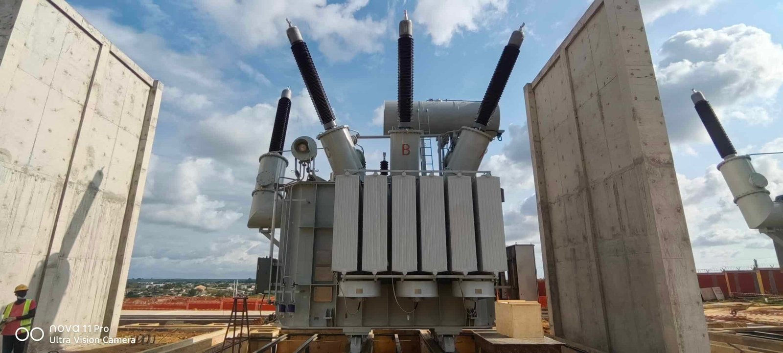
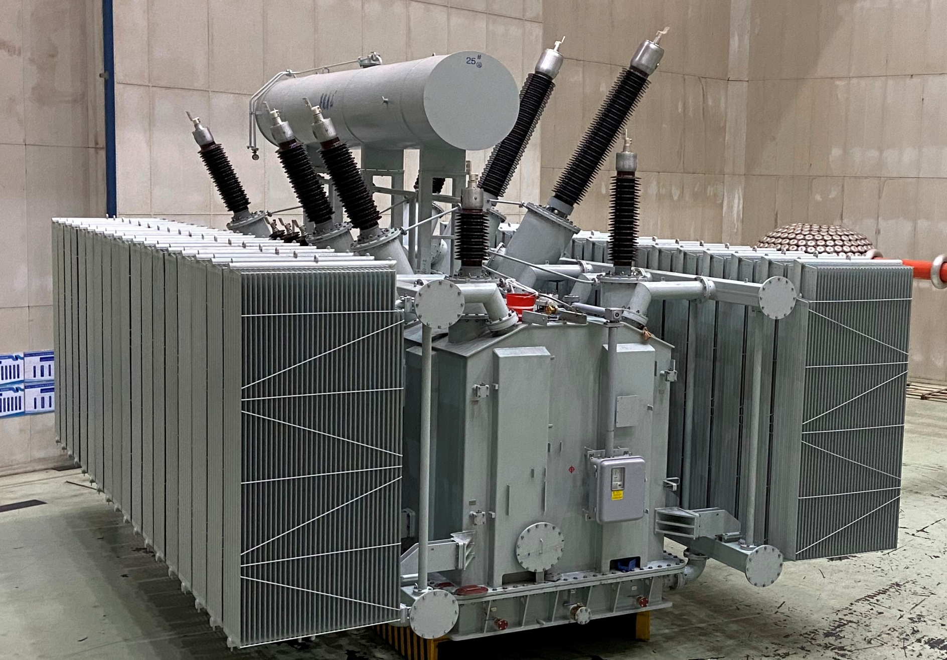
Radiators are essential cooling components in oil-immersed transformers, designed to dissipate heat generated during operation. As transformers carry electrical load, both core and winding losses produce heat that must be effectively removed to prevent insulation aging and performance degradation. Radiators increase the surface area available for heat exchange, helping maintain safe operating temperatures and extending transformer lifespan.
What Is the Primary Function of Radiators in Transformers?
![]()
Radiators are critical components in oil-immersed transformers, serving as the main external heat dissipation system. Without them, heat generated inside the transformer would accumulate, causing excessive oil temperature, insulation degradation, reduced efficiency, and shortened service life.
The primary function of transformer radiators is to transfer heat from the hot insulating oil inside the transformer to the surrounding ambient air, thereby maintaining safe operating temperatures.
1. Why Heat Removal Is Necessary
Inside a transformer, heat is continuously generated due to:
- Copper (load) losses in windings
- Core (no-load) losses in the magnetic core
This heat raises the temperature of the insulating oil. If not removed effectively:
- Oil viscosity decreases
- Insulation ages faster
- Winding hot spots increase
- Overload capacity decreases
- Risk of failure rises
Radiators prevent these problems by enabling continuous heat exchange.
2. How Radiators Work
Radiators operate based on natural or forced convection.
Step-by-step process:
- Windings heat the transformer oil.
- Hot oil rises naturally due to lower density.
- Oil flows into radiator panels or tubes.
- Heat transfers through radiator walls to ambient air.
- Cooled oil becomes denser and flows back into the tank.
This circulation cycle continues automatically in natural cooling systems.
3. Heat Transfer Mechanism
Heat transfer occurs in three stages:
- Conduction – Heat moves from oil to radiator metal surface.
- Convection – Heat transfers from radiator surface to surrounding air.
- Radiation – A small portion of heat radiates outward.
The efficiency of this process depends on:
- Radiator surface area
- Airflow conditions
- Ambient temperature
- Oil circulation rate
Larger surface area = greater heat dissipation capacity.
4. Types of Radiator Cooling Modes
Radiators are used in different cooling configurations:
ONAN (Oil Natural Air Natural)
- Natural oil circulation
- Natural air convection
- No moving parts
ONAF (Oil Natural Air Forced)
- Natural oil flow
- Fans improve air cooling
OFAF (Oil Forced Air Forced)
- Oil pumps circulate oil
- Fans increase air cooling
As transformer rating increases, forced cooling is typically added.
5. Why Radiators Are More Effective Than Tank Cooling Alone
A transformer tank alone cannot provide sufficient surface area for large heat loads.
Radiators:
- Increase effective cooling surface
- Improve oil circulation paths
- Allow modular expansion for higher ratings
For large transformers, radiator banks significantly extend cooling capability without enlarging the main tank excessively.
6. Impact on Transformer Performance
Effective radiator design ensures:
- Controlled oil temperature rise
- Lower winding hot spot temperature
- Extended insulation life
- Improved overload capability
- Stable efficiency under varying loads
A 10°C reduction in operating temperature can nearly double insulation life.
7. Design Considerations
Radiator performance depends on:
- Number and size of panels
- Fin spacing
- Material (usually steel)
- Airflow exposure
- Cleanliness of surfaces
Blocked airflow or dirt accumulation reduces cooling efficiency.
8. Practical Example
Consider a 25 MVA oil-immersed transformer:
- Total losses: ~200 kW
- Radiator system must dissipate 200,000 watts continuously
- Without adequate radiator area, oil temperature would exceed design limits
Proper radiator sizing ensures safe temperature rise even during peak load conditions.
How Do Radiators Transfer Heat from Transformer Oil to the Surrounding Air?
Transformer overheating is one of the most common causes of insulation failure and premature aging in oil-immersed units. When internal copper and core losses generate heat, that energy must be removed continuously to maintain safe operating temperatures. If heat remains trapped inside the tank, oil temperature rises, winding hot spots intensify, and insulation life shortens dramatically.
Radiators transfer heat from transformer oil to surrounding air through a three-stage heat transfer process involving internal oil convection, metal wall conduction, and external air convection and radiation. Hot oil circulates into the radiator panels, releases heat through the steel walls, and cooled oil returns to the transformer tank, maintaining thermal balance.
Understanding this process helps engineers optimize cooling performance and extend transformer service life.
Heat transfer in transformer radiators may appear simple from the outside, but it is a carefully engineered thermodynamic process involving fluid dynamics, thermal gradients, and surface geometry optimization. Let us examine each stage in detail.
Transformer radiators only cool by radiation.False
Transformer radiators dissipate heat primarily through convection (oil and air movement), while radiation contributes only a smaller portion of total heat transfer.
1. Stage One: Heat Absorption and Oil Convection Inside the Transformer
Inside an oil-immersed transformer, heat originates from:
- Copper (I²R) losses in windings
- Core (hysteresis and eddy current) losses
These losses heat the surrounding insulating oil. As oil temperature increases, its density decreases. This density difference initiates natural convection circulation.
Process inside the tank:
- Hot oil rises toward the top of the transformer tank.
- Cooler oil sinks to the bottom.
- Oil flows through connecting pipes into the radiator bank.
This movement occurs continuously in natural cooling systems such as ONAN.
In forced cooling systems (OFAF):
- Oil pumps actively circulate oil
- Flow rate increases
- Heat transfer efficiency improves
Oil convection is the first critical step in moving heat away from windings.
2. Stage Two: Conduction Through Radiator Walls
Once hot oil enters the radiator panels or tubes, heat must pass through the metal walls.
Radiators are typically made of:
- Welded steel panels
- Tubular steel elements
Heat transfer here follows Fourier’s Law of Conduction:
Q = k × A × (ΔT / d)
Where:
- Q = heat transfer rate
- k = thermal conductivity of steel
- A = surface area
- ΔT = temperature difference
- d = wall thickness
Key design factors:
- Large surface area increases heat flow
- Thin walls improve conduction
- High thermal conductivity materials enhance efficiency
Steel provides a good balance between mechanical strength and adequate thermal conductivity.
3. Stage Three: Heat Dissipation to Ambient Air
Once heat reaches the outer surface of the radiator, it transfers to surrounding air through:
- Natural air convection
- Forced air convection (if fans are used)
- Thermal radiation
Natural convection works as follows:
- Air in contact with hot radiator surface warms
- Warm air becomes less dense and rises
- Cooler air replaces it
- Continuous airflow removes heat
Forced air cooling enhances this process by using fans to increase airflow velocity.
The convective heat transfer rate depends on:
- Air velocity
- Temperature difference
- Surface geometry
- Ambient conditions
Radiation contributes a smaller percentage but becomes more significant at higher surface temperatures.
4. Complete Heat Transfer Path
The full thermal path can be summarized:
Windings → Oil → Radiator Inner Wall → Radiator Outer Wall → Air
Each stage introduces thermal resistance.
Total heat transfer depends on:
- Oil flow rate
- Radiator surface area
- Airflow rate
- Ambient temperature
- Cleanliness of surfaces
Designers aim to minimize overall thermal resistance.
5. Influence of Cooling Modes
Different cooling classifications improve heat transfer efficiency:
ONAN (Oil Natural Air Natural)
- Relies entirely on natural convection
ONAF (Oil Natural Air Forced)
- Fans increase air convection
OFAF (Oil Forced Air Forced)
- Pumps increase oil flow
- Fans increase air movement
As transformer ratings increase, forced cooling systems are often required to manage higher thermal loads.
6. Radiator Surface Geometry and Heat Transfer Enhancement
Radiator efficiency depends heavily on surface design.
Common design features:
- Corrugated panels to increase surface area
- Vertical channels to support oil flow
- Fin spacing optimized for airflow
- Modular radiator banks for scalability
More surface area equals greater heat exchange capacity.
7. Environmental Factors Affecting Heat Transfer
External conditions significantly influence radiator performance.
- High ambient temperature reduces temperature gradient
- Low wind speed reduces natural convection
- Dust accumulation reduces heat transfer
- Solar radiation may increase tank temperature
Proper installation orientation and maintenance are critical.
8. Practical Engineering Example
Consider a 20 MVA transformer with total losses of 150 kW.
The radiator system must dissipate:
150,000 watts continuously.
If ambient temperature rises:
- ΔT decreases
- Cooling efficiency drops
- Oil temperature increases
Adding forced air cooling increases convective coefficient and restores heat balance.
9. Why Radiator Maintenance Matters
Heat transfer efficiency declines when:
- Radiator fins become clogged
- Oil flow passages are obstructed
- Fans fail
- Oil viscosity changes
Regular inspection ensures maximum cooling capacity.
What Is the Difference Between Natural and Forced Oil Cooling with Radiators?

Overheating remains one of the most critical risks in oil-immersed transformers. As load increases, copper and core losses generate significant heat inside the tank. If this heat is not efficiently removed, oil temperature rises, insulation ages faster, and transformer lifespan is drastically reduced. Many users assume that all radiator systems perform similarly, but the choice between natural and forced oil cooling fundamentally changes thermal performance, overload capability, operating cost, and reliability.
The difference between natural and forced oil cooling with radiators lies in how the insulating oil circulates: natural oil cooling relies on density-driven convection without pumps, while forced oil cooling uses mechanical pumps to actively circulate oil through radiators, significantly increasing heat transfer efficiency and cooling capacity.
Understanding this distinction is essential when selecting cooling systems for different transformer ratings and applications.
Forced oil cooling always requires water cooling.False
Forced oil cooling may use air-cooled radiators (OFAF) or water-cooled heat exchangers (OFWF); water cooling is not mandatory.
1. Fundamental Operating Principle
1.1 Natural Oil Cooling (ON)
Natural oil cooling operates entirely through thermodynamic principles.
Process:
- Windings generate heat.
- Surrounding oil warms and expands.
- Hot oil rises due to lower density.
- Cooler oil sinks.
- Circulation continues without mechanical assistance.
Oil flows through radiators passively, driven by temperature gradients.
There are no pumps involved.
This method is used in:
- ONAN (Oil Natural Air Natural)
- ONAF (Oil Natural Air Forced, oil still natural)
1.2 Forced Oil Cooling (OF)
Forced oil cooling introduces oil pumps to increase circulation rate.
Process:
- Oil pumps push hot oil into radiator banks.
- Oil flow velocity increases.
- Thermal boundary layer thickness decreases.
- Heat transfer rate improves.
Used in:
- OFAF (Oil Forced Air Forced)
- OFWF (Oil Forced Water Forced)
Mechanical circulation dramatically increases cooling efficiency.
2. Heat Transfer Performance Comparison
Heat removal depends on:
- Oil flow rate
- Temperature difference
- Surface area
- Airflow
Increasing oil velocity improves convective heat transfer coefficient.
Comparative Performance Table
| Parameter | Natural Oil Cooling | Forced Oil Cooling |
|---|---|---|
| Oil Circulation | Density-driven | Pump-driven |
| Flow Rate | Low to moderate | High |
| Cooling Efficiency | Moderate | High |
| Suitable Rating | Small–medium | Medium–very large |
| Overload Capability | Limited | Enhanced |
| Auxiliary Power | None (oil side) | Required |
| System Complexity | Simple | Complex |
Forced oil cooling can increase heat removal capacity by 20–50% compared to natural oil systems of similar radiator size.
3. Impact on Transformer Rating
Natural oil cooling is typically used for:
- Distribution transformers
- Medium power transformers up to ~20–30 MVA
Forced oil cooling becomes necessary for:
- Large power transformers
- Units above ~30–40 MVA
- High-loss applications
Higher ratings generate higher losses, requiring greater thermal management.
4. Influence on Radiator Design
With natural oil cooling:
- Larger radiator surface area is required
- Vertical orientation supports convection
- Flow channels must minimize resistance
With forced oil cooling:
- Smaller radiators can handle same heat load
- Oil velocity improves heat extraction
- More compact transformer design possible
Forced systems allow higher power density.
5. Overload Performance Differences
Natural Oil Cooling:
- Limited overload duration
- Oil temperature rises gradually
- Risk of localized hot spots
Forced Oil Cooling:
- Faster heat removal
- Better hot spot control
- Higher short-term overload capability
This is especially important in renewable energy and grid fluctuation environments.
6. Reliability and Maintenance Considerations
Natural Oil Cooling Advantages:
- No oil pumps
- Fewer mechanical parts
- Lower failure probability
- Minimal maintenance
Forced Oil Cooling Considerations:
- Pumps require maintenance
- Auxiliary power supply needed
- Control systems required
- Redundancy often installed
Utilities often include dual pumps for critical transformers.
7. Energy Consumption Differences
Natural oil systems:
- No oil pump power consumption
- Only fans (if ONAF)
Forced oil systems:
- Oil pump energy consumption
- Fan energy consumption
- Slightly higher operational cost
However, improved thermal performance may reduce long-term aging costs.
8. Cost Comparison
| Cost Aspect | Natural Oil Cooling | Forced Oil Cooling |
|---|---|---|
| Initial Cost | Lower | Higher |
| Installation Complexity | Low | Moderate–High |
| Operating Cost | Low | Moderate |
| Maintenance Cost | Low | Moderate |
| Lifecycle Flexibility | Moderate | High |
For large transformers, forced oil cooling becomes economically justified.
9. Application Examples
Example 1: 10 MVA Substation Transformer
- ONAN sufficient
- Moderate load
- Outdoor installation
Example 2: 60 MVA Industrial Transformer
- OFAF required
- High continuous load
- Limited footprint
Example 3: 200 MVA Transmission Transformer
- OFWF common
- High loss density
- Water cooling available
Application scale determines cooling choice.
10. Thermal Stability and Hot Spot Control
The most critical temperature is winding hot spot temperature.
Natural oil systems:
- Slower oil turnover
- Larger thermal gradients
Forced oil systems:
- Uniform temperature distribution
- Reduced hot spot rise
- Improved insulation lifespan
A reduction of even 5–8°C in hot spot temperature can significantly extend transformer life.
How Does Radiator Design Affect Cooling Efficiency?
Transformer overheating is rarely caused by oil quality alone—it is most often a cooling design issue. When radiator design is inadequate, even a correctly sized transformer can suffer from elevated oil temperature, higher winding hot spots, accelerated insulation aging, and reduced overload capability. Poor surface geometry, insufficient oil flow channels, or improper airflow spacing can quietly reduce heat dissipation performance for decades.
Radiator design directly affects cooling efficiency by determining the available heat transfer surface area, oil flow distribution, airflow exposure, thermal resistance, and overall heat dissipation capacity. Optimized geometry, proper material thickness, effective oil channel design, and enhanced airflow management significantly improve transformer thermal performance and lifespan.
Understanding how radiator engineering influences heat transfer allows utilities and industrial users to make better equipment decisions.
Increasing radiator surface area always guarantees proportional cooling improvement.False
While larger surface area improves heat dissipation, airflow limitations, oil circulation constraints, and thermal resistance can reduce proportional gains. Effective design requires balanced optimization.
1. Core Heat Transfer Principles in Radiator Design
Radiator efficiency is governed by three primary heat transfer mechanisms:
- Oil-side convection (inside the radiator)
- Conduction through metal walls
- Air-side convection and radiation (outside surface)
The overall heat transfer rate can be simplified as:
Q = U × A × ΔT
Where:
- Q = heat dissipated
- U = overall heat transfer coefficient
- A = effective surface area
- ΔT = temperature difference between oil and ambient air
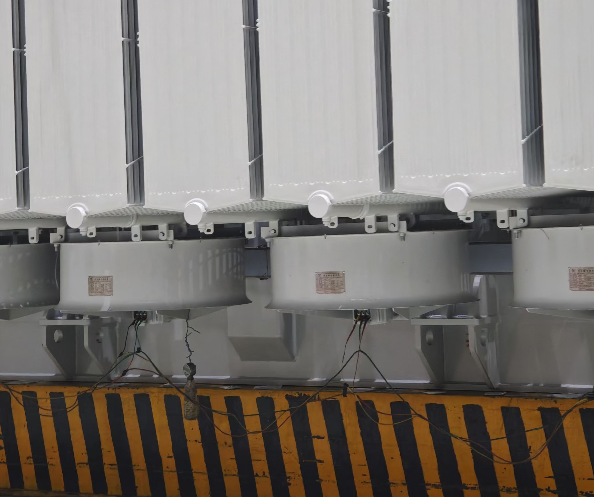
Radiator design directly influences both A (surface area) and U (heat transfer coefficient).
2. Surface Area and Geometry Optimization
2.1 Why Surface Area Matters
The greater the external surface area exposed to air, the more heat can be transferred.
Radiator surface area depends on:
- Panel height
- Number of panels
- Corrugation depth
- Fin spacing
However, increasing surface area alone is not sufficient if airflow is restricted.
2.2 Corrugated Panel Design
Modern radiators use corrugated or folded steel panels because:
- Corrugations increase surface area
- Vertical channels support oil circulation
- Structural strength improves
Poorly designed corrugations can create stagnant oil zones, reducing cooling efficiency.
3. Oil Flow Channel Design
Efficient oil circulation inside radiator panels is critical.
Key factors:
- Vertical channel width
- Flow resistance
- Pressure drop
- Uniform distribution across panels
In natural oil systems (ONAN):
- Flow depends on density difference
- Channels must minimize resistance
In forced oil systems (OFAF):
- Pumps increase flow velocity
- Channel design must avoid turbulence losses
Oil Flow Comparison
| Feature | Poor Design | Optimized Design |
|---|---|---|
| Flow Distribution | Uneven | Uniform |
| Thermal Gradient | High | Balanced |
| Dead Zones | Present | Minimized |
| Heat Transfer | Reduced | Enhanced |
Uniform oil distribution prevents hot spots.
4. Wall Thickness and Material Selection
Radiator walls are typically made of steel.
Design balance is required:
- Thinner walls improve conduction
- Thicker walls improve durability
If walls are too thick:
- Thermal resistance increases
- Heat transfer slows
If walls are too thin:
- Structural integrity compromised
- Risk of leakage increases
Optimized thickness ensures safe and efficient conduction.
5. Airflow Exposure and Spacing
Air-side convection is often the limiting factor.
Key design considerations:
- Panel spacing for natural airflow
- Fan placement in forced systems
- Avoiding airflow blockage
- Orientation relative to prevailing wind
Insufficient spacing reduces airflow velocity and cooling efficiency.
Natural vs. Forced Air Cooling
| Parameter | Natural Air | Forced Air |
|---|---|---|
| Air Velocity | Low | High |
| Heat Transfer Coefficient | Moderate | High |
| Noise Level | Low | Higher |
| Cooling Capacity | Moderate | Increased |
Fan-assisted systems significantly increase convective heat transfer coefficient.
6. Radiator Height and Vertical Flow Dynamics
Height influences oil convection efficiency.
Taller radiators:
- Increase gravitational pressure head
- Improve natural circulation
- Enhance oil turnover rate
However, excessive height may:
- Increase structural stress
- Complicate installation
Engineering design optimizes height for maximum convection efficiency.
7. Number of Radiator Banks
Multiple radiator banks improve:
- Heat distribution
- Redundancy
- Cooling scalability
For large transformers:
- Radiator banks may be divided into stages
- Fans activate progressively under high load
This staged cooling improves efficiency and energy savings.
8. Environmental Influences on Radiator Efficiency
Radiator performance is influenced by:
- Ambient temperature
- Solar radiation exposure
- Dust accumulation
- Wind patterns
High ambient temperature reduces ΔT, lowering heat transfer rate.
Dust accumulation increases surface thermal resistance.
Routine maintenance preserves cooling efficiency.
9. Power Density and Radiator Design
Higher power density transformers generate more losses per unit volume.
To compensate:
- Radiator surface area must increase
- Oil flow rate must increase
- Forced cooling often required
Modern compact transformer designs depend heavily on optimized radiator systems.
10. Practical Engineering Example
Consider a 40 MVA transformer generating 300 kW of losses.
Scenario A: Standard radiator design
- Moderate surface area
- Natural oil flow
- Oil temperature rise: 55°C
Scenario B: Optimized radiator with forced cooling
- Increased surface area
- Pump-assisted circulation
- Oil temperature rise: 45°C
A 10°C reduction significantly extends insulation life.
Transformer insulation life approximately halves for every 6–8°C increase in temperature.
11. Impact on Transformer Lifespan and Efficiency
Improved radiator design:
- Reduces oil temperature
- Reduces winding hot spot
- Extends insulation life
- Increases overload capability
- Maintains stable efficiency
Poor radiator design results in:
- Chronic overheating
- Accelerated aging
- Reduced reliability
- Increased maintenance costs
Cooling efficiency directly determines long-term transformer performance.
12. Design Innovations in Modern Radiators
Advanced manufacturing techniques now include:
- Laser-welded panels for leak prevention
- Finite element thermal simulation
- CFD airflow modeling
- Anti-corrosion coatings
- Modular bolt-on radiator systems
These improvements enhance heat transfer consistency and durability.
When Are Fans or Pumps Used with Radiator Systems?
Transformer cooling systems are designed to maintain safe operating temperatures under varying load conditions. However, natural cooling through radiators alone is not always sufficient—especially when transformers operate near rated capacity, experience overloads, or are installed in high ambient temperature environments. If auxiliary cooling devices are not properly applied when required, excessive oil and winding temperatures can accelerate insulation aging, reduce efficiency, and significantly shorten transformer service life.
Fans and pumps are used with radiator systems when natural oil and air convection cannot dissipate the total heat generated by transformer losses. Fans increase air-side heat transfer (ONAF/OFAF), while pumps actively circulate oil to enhance internal convection (OFAF/OFWF), allowing higher load capacity, improved thermal control, and increased overload capability.
Understanding when and why auxiliary cooling is required is essential for reliable transformer operation and optimal lifecycle performance.
Cooling fans are always running in oil-immersed transformers.False
Cooling fans operate automatically based on oil temperature or load conditions and are typically activated in stages when additional cooling is required.
1. Basic Cooling Modes Overview
Transformer radiator systems are categorized according to oil and air circulation methods:
- ONAN – Oil Natural Air Natural
- ONAF – Oil Natural Air Forced
- OFAF – Oil Forced Air Forced
- OFWF – Oil Forced Water Forced
Fans affect the air side, while pumps affect the oil side.
2. When Are Cooling Fans Used?
Cooling fans are added when:
- Transformer rating increases beyond natural air cooling capacity
- Load profile includes frequent peak demands
- Ambient temperature is high
- Space limitations restrict radiator surface area
- Overload capability is required
2.1 Transition from ONAN to ONAF
In ONAF systems:
- Oil circulates naturally
- Fans increase airflow across radiators
This increases the air-side convective heat transfer coefficient.
Typical improvement:
- Cooling capacity increases by 20–40%
- Transformer can operate at higher load without excessive temperature rise
2.2 Staged Fan Operation
Fans typically operate in stages:
| Stage | Oil Temperature | Cooling Mode |
|---|---|---|
| Stage 1 | Normal load | Natural cooling |
| Stage 2 | Moderate temperature rise | First fan group activated |
| Stage 3 | High load | Additional fans activated |
This staged approach:
- Reduces energy consumption
- Minimizes wear
- Extends fan lifespan
3. When Are Oil Pumps Used?
Oil pumps are used when natural oil circulation becomes insufficient.
This typically occurs in:
- Large power transformers (>30–40 MVA)
- High-loss density designs
- Compact transformers with limited radiator area
- Applications requiring rapid heat removal
In OFAF systems:
- Pumps force oil through radiators
- Oil velocity increases
- Thermal boundary layer thickness decreases
- Internal heat transfer improves significantly
4. Technical Difference Between Fans and Pumps
| Parameter | Cooling Fans | Oil Pumps |
|---|---|---|
| Act On | Air side | Oil side |
| Improve | External convection | Internal convection |
| Complexity | Moderate | Higher |
| Maintenance | Low–Moderate | Moderate–High |
| Power Consumption | Low | Moderate |
| Typical Application | Medium transformers | Large power transformers |
Pumps provide greater thermal enhancement than fans but introduce additional system complexity.
5. When Natural Cooling Is Sufficient
Fans and pumps are not always necessary.
Natural cooling (ONAN) is sufficient when:
- Transformer rating is relatively small
- Continuous load is below design threshold
- Ambient temperature is moderate
- Overload operation is limited
Natural cooling advantages:
- No moving parts
- Lower maintenance
- Higher mechanical reliability
- Lower operating cost
However, its cooling capacity is inherently limited.
6. Influence of Load Profile
Load behavior strongly determines auxiliary cooling needs.
6.1 Stable Base Load
If load remains steady and below rated capacity:
- Natural cooling often adequate
6.2 Cyclic or Peak Load
In industrial facilities or renewable integration:
- Load fluctuates
- Thermal stress increases
- Fans or pumps may activate during peak hours
Auxiliary cooling enables safe short-term overloading.
7. Ambient Temperature Considerations
High ambient temperature reduces temperature difference (ΔT) between oil and air.
As ΔT decreases:
- Heat transfer efficiency declines
- Oil temperature rises faster
In hot climates:
- Fans are often standard
- Pumps may be required for larger units
For example:
At 40°C ambient temperature, natural cooling may not maintain acceptable oil temperature rise.
8. Compact Design and Space Constraints
Modern substations often require compact footprints.
If radiator area is restricted:
- Forced air cooling compensates for reduced surface area
- Forced oil cooling increases thermal density
This enables:
- Smaller transformer tanks
- Higher power density
- Improved urban deployment
9. Overload Capability Requirements
Utilities often require transformers to handle emergency overloads.
Auxiliary cooling allows:
- Temporary load increase
- Controlled hot spot temperature
- Extended emergency operation
Without fans or pumps:
- Overload duration must be shorter
- Insulation aging accelerates
10. Reliability and Redundancy
Because pumps and fans are mechanical devices:
- Redundant systems are often installed
- Dual pumps or multiple fan banks used
This ensures cooling remains available even if one component fails.
Proper monitoring systems detect:
- Pump failure
- Fan malfunction
- Temperature abnormality
11. Energy and Lifecycle Cost Considerations
While auxiliary cooling increases operational energy consumption:
- Improved thermal control reduces insulation aging
- Transformer lifespan increases
- Long-term cost savings achieved
Lifecycle economic analysis often justifies auxiliary cooling for medium and large transformers.
12. Practical Application Examples
Example 1: 10 MVA distribution transformer
- ONAN sufficient
- No fans or pumps required
Example 2: 40 MVA industrial transformer
- ONAF used
- Fans activated during peak load
Example 3: 150 MVA transmission transformer
- OFAF system
- Pumps and fans continuously staged
Cooling strategy scales with transformer size and load demand.
How Do Radiators Contribute to Transformer Reliability and Longevity?
Transformer failures rarely occur suddenly without warning; in most cases, they are the result of chronic thermal stress accumulated over years of operation. Excessive oil temperature, uneven heat distribution, and persistent winding hot spots gradually weaken insulation systems, accelerate paper degradation, and reduce dielectric strength. Without an effective cooling mechanism, even a well-designed transformer will experience shortened service life and increased failure risk. Radiators are not merely external attachments—they are critical thermal management components that directly determine transformer durability.
Radiators contribute to transformer reliability and longevity by continuously dissipating internal heat, stabilizing oil temperature, reducing winding hot spots, slowing insulation aging, improving overload capacity, and maintaining consistent thermal balance throughout the transformer’s operational life.
Understanding how radiator performance influences long-term reliability is essential for utilities, industrial operators, and infrastructure planners.
Transformer lifespan is mainly determined by mechanical strength rather than temperature.False
Transformer lifespan is primarily determined by insulation aging, which is highly dependent on operating temperature and thermal management efficiency.
1. The Direct Relationship Between Temperature and Transformer Life
Transformer aging is largely governed by insulation degradation. The insulation system consists of:
- Cellulose-based paper insulation
- Pressboard components
- Mineral or ester insulating oil
Cellulose aging follows the Arrhenius reaction principle, meaning temperature rise accelerates chemical degradation exponentially.
Industry rule of thumb:
For every 6–8°C increase in winding hot spot temperature, insulation life is approximately halved.
This makes temperature control the single most important factor in transformer longevity.
Radiators serve as the primary mechanism for controlling that temperature.
2. Stabilizing Oil Temperature
Radiators remove heat generated from:
- Copper (I²R) losses
- Core losses
Without effective heat removal:
- Oil viscosity decreases
- Dielectric strength weakens
- Oxidation accelerates
Radiators maintain oil temperature within design limits, typically:
- Top oil rise: 50–60°C above ambient
- Hot spot temperature: within insulation class limits
Stable oil temperature ensures consistent dielectric performance.
3. Reduction of Winding Hot Spots
Hot spots occur at localized regions in the windings where:
- Current density is high
- Oil circulation is limited
Radiator efficiency improves oil turnover rate and thermal gradient distribution.
Better cooling:
- Reduces peak hot spot temperature
- Minimizes thermal stress
- Balances internal temperature distribution
Uniform temperature distribution significantly extends insulation integrity.
4. Impact on Insulation Aging Rate
Thermal Aging Comparison
| Hot Spot Temperature | Relative Aging Rate | Estimated Insulation Life |
|---|---|---|
| 95°C | 1x | 100% design life |
| 101°C | 2x | ~50% life |
| 110°C | 4x | ~25% life |
| 120°C | 8x | Rapid failure risk |
Even small improvements in radiator efficiency can lower operating temperature by several degrees, dramatically extending transformer lifespan.
5. Supporting Overload Capability
In practical grid operations, transformers rarely operate at constant load.
Load variations include:
- Daily peak demand
- Seasonal changes
- Emergency overloads
Efficient radiators:
- Allow safe temporary overload
- Prevent excessive oil temperature rise
- Provide thermal buffer capacity
Without sufficient radiator performance:
- Overload duration must be shortened
- Risk of accelerated aging increases
Radiator capacity directly influences operational flexibility.
6. Prevention of Thermal Runaway
Thermal runaway occurs when:
- Heat generation exceeds heat dissipation
- Oil temperature rises uncontrollably
- Insulation degradation accelerates
Radiators prevent this scenario by ensuring continuous heat removal under all rated conditions.
Reliable heat transfer prevents cascading thermal failure.
7. Maintaining Oil Quality
Oil oxidation increases with temperature.
High temperatures accelerate:
- Sludge formation
- Acid generation
- Moisture absorption
- Dielectric breakdown
Radiators indirectly preserve oil quality by keeping temperatures lower, slowing oxidation reactions, and reducing maintenance frequency.
Lower oil degradation = fewer oil filtration interventions.
8. Mechanical Reliability of the Transformer Tank
Excessive internal temperature causes:
- Thermal expansion stress
- Gasket aging
- Seal deterioration
- Weld fatigue
Effective radiators reduce internal pressure fluctuations and thermal cycling stress.
Reduced thermal stress improves:
- Tank integrity
- Leak prevention
- Structural stability
This contributes significantly to long-term mechanical reliability.
9. Cooling System Design and Redundancy
Modern radiator systems are often designed with:
- Multiple radiator banks
- Staged fan operation
- Redundant oil pumps
This redundancy ensures continued cooling even if one component fails.
Higher reliability cooling systems:
- Reduce forced outages
- Improve service continuity
- Protect critical infrastructure
10. Comparison of Cooling Performance Impact
| Cooling Condition | Oil Temperature Stability | Aging Rate | Reliability Impact |
|---|---|---|---|
| Inadequate Radiator Design | Poor | High | Increased failure risk |
| Standard Radiator Design | Moderate | Normal | Acceptable |
| Optimized Radiator with Forced Cooling | Excellent | Reduced | High reliability |
Transformer reliability is directly linked to cooling system effectiveness.
11. Long-Term Economic Benefits
Radiator efficiency impacts total lifecycle cost.
Improved cooling results in:
- Extended service life (30–40+ years)
- Reduced maintenance frequency
- Fewer forced outages
- Lower replacement cost risk
- Improved asset utilization
Investing in proper radiator design often provides greater return than marginal improvements in core efficiency alone.
12. Practical Engineering Example
Consider two 50 MVA transformers:
Transformer A:
- Standard radiator
- Top oil rise: 60°C
Transformer B:
- Enhanced radiator design
- Top oil rise: 52°C
A 8°C difference may double insulation life expectancy.
Over 30 years, this difference can determine whether a transformer requires early replacement or continues operating reliably.
13. Environmental and Grid Stability Benefits
Reliable transformers:
- Reduce outage risk
- Prevent catastrophic failures
- Support stable power supply
- Enhance grid resilience
Cooling reliability contributes to system-level stability.
Radiators therefore play a role not only in equipment longevity but also in overall power infrastructure reliability.
Conclusion
Radiators play a vital role in maintaining thermal balance in oil-immersed transformers by transferring heat from the internal insulating oil to the surrounding air. Whether operating through natural convection or assisted by fans and oil pumps, radiator systems ensure that transformers remain within safe temperature limits. Proper radiator design and maintenance significantly enhance cooling efficiency, improve reliability, and extend the overall service life of the transformer.
FAQ
Q1: What is the role of radiators in transformers?
Radiators in transformers are used to dissipate heat generated during operation. As electrical energy flows through the transformer windings and core, losses occur in the form of heat. Radiators increase the external surface area of the transformer, allowing heat to be transferred from the insulating oil to the surrounding air.
By removing excess heat, radiators help maintain safe operating temperatures and prevent overheating, which could otherwise damage insulation and shorten transformer lifespan.
Q2: How do transformer radiators work?
In oil-immersed transformers, insulating oil circulates between the main tank and the radiator panels. The process works as follows:
Heat from the windings warms the transformer oil.
The hot oil rises and flows into the radiator tubes or panels.
Heat transfers through the radiator walls to the surrounding air.
As the oil cools, it becomes denser and flows back into the transformer tank.
This natural convection cycle continuously removes heat from the transformer.
Q3: Why are radiators necessary in large transformers?
Large power transformers generate significant heat due to higher load currents and core losses. Without sufficient cooling surface area, the internal temperature would rise quickly.
Radiators provide the additional cooling area needed to:
Maintain acceptable oil and winding temperatures
Support higher power ratings
Ensure long insulation life
Prevent thermal degradation of components
As transformer capacity increases, the number and size of radiators typically increase as well.
Q4: What types of radiator cooling systems are used?
Radiator cooling can operate under different cooling modes, including:
ONAN (Oil Natural Air Natural): Natural oil circulation and natural air cooling
ONAF (Oil Natural Air Forced): Fans assist air flow across radiators
OFAF (Oil Forced Air Forced): Oil pumps and fans enhance heat removal
OFWF (Oil Forced Water Forced): Heat exchangers use water cooling for very large units
These systems allow transformers to operate efficiently under various load conditions.
Q5: What are transformer radiators typically made of?
Radiators are usually made of steel panels or tubes designed for durability and efficient heat transfer. They are welded or bolted to the transformer tank and coated with protective paint to resist corrosion.
The design must withstand:
Thermal expansion and contraction
Environmental exposure
Mechanical stress during transport and operation
Proper material selection ensures long-term reliability.
Q6: How do radiators affect transformer efficiency and reliability?
Effective radiator cooling helps maintain lower operating temperatures, which:
Reduces insulation aging
Maintains electrical performance
Improves transformer reliability
Extends service life
Since insulation life is strongly temperature-dependent, efficient heat dissipation plays a major role in long-term transformer health.
Q7: Can radiator performance be improved or upgraded?
Yes. Radiator cooling performance can be enhanced by:
Adding forced-air cooling fans
Installing oil circulation pumps
Increasing radiator surface area
Cleaning and maintaining radiator surfaces
Regular inspection ensures that radiators remain free of dirt, corrosion, or oil flow restrictions that could reduce cooling efficiency.
Q8: Are radiators used in dry-type transformers?
No. Dry-type transformers do not use radiators because they do not contain insulating oil. Instead, they rely on air natural (AN) or air forced (AF) cooling systems to dissipate heat directly through the windings and core.
Radiators are therefore specific to oil-immersed transformer cooling systems.
References
IEC 60076 – Power Transformers
https://webstore.iec.ch/publication/602
IEEE C57 Series – Transformer Cooling and Thermal Performance
https://standards.ieee.org
Electrical Engineering Portal – Transformer Cooling Methods Explained
https://electrical-engineering-portal.com
CIGRE – Transformer Thermal Design Studies
https://www.cigre.org
NEMA – Transformer Design and Cooling Guidelines
https://www.nema.org
IEEE Power & Energy Society – Transformer Cooling Research
https://ieeexplore.ieee.org
