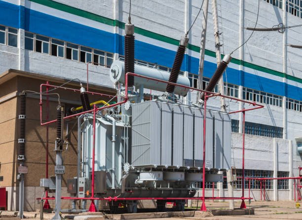
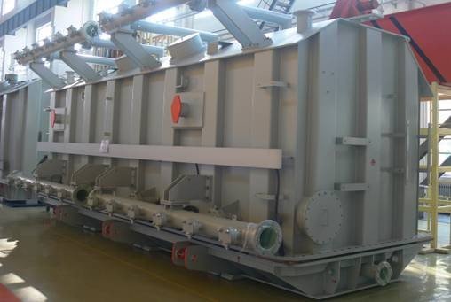
Oil-immersed transformers are key assets in power systems, designed to handle high voltage and large-capacity energy transfer with strong insulation and effective cooling. Their internal structure integrates multiple components that work together to ensure safe, efficient, and stable operation. Understanding both the internal structure and working principle is essential for proper operation, maintenance, and performance optimization.
What Are the Main Internal Components of an Oil-Immersed Transformer?
In high-voltage power systems, oil-immersed transformers are critical assets responsible for efficient energy transmission and distribution. However, their performance and reliability depend entirely on the integrity and coordination of their internal components. If any internal part—such as the core, windings, or insulation system—fails or degrades, it can lead to overheating, energy losses, or catastrophic breakdown. Understanding these internal components is essential not only for design and manufacturing but also for maintenance, diagnostics, and long-term optimization.
The main internal components of an oil-immersed transformer include the magnetic core, primary and secondary windings, insulating oil, solid insulation system, tap changer, internal leads and connections, and structural support components, all working together to transfer electrical energy efficiently while ensuring insulation, cooling, and mechanical stability.
To fully understand how these components interact, each must be examined in detail from an engineering perspective.
The oil inside a transformer is only used for cooling and has no insulating function.False
Transformer oil serves both as a cooling medium and as a critical electrical insulation material.
1. Magnetic Core
The magnetic core is the central component responsible for transferring magnetic flux between the primary and secondary windings. It is typically made of laminated silicon steel sheets to reduce energy losses caused by eddy currents and hysteresis.
The laminations are insulated from each other to prevent circulating currents, improving efficiency and reducing heat generation.
| Core Feature | Function | Benefit |
|---|---|---|
| Laminated structure | Reduce eddy currents | Lower losses |
| Silicon steel material | High magnetic permeability | Efficient energy transfer |
| Core clamping system | Maintain structural integrity | Reduced vibration |
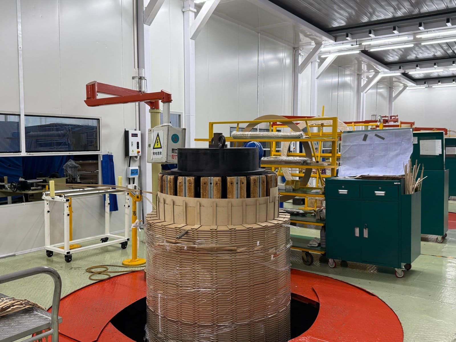
2. Windings (Primary and Secondary)
Windings are responsible for carrying electrical current and enabling voltage transformation. The primary winding receives input voltage, while the secondary winding delivers output voltage.
They are typically made of copper or aluminum conductors and are carefully insulated to prevent short circuits.
| Winding Type | Function | Design Consideration |
|---|---|---|
| Primary winding | Receives input power | High voltage insulation |
| Secondary winding | Delivers output power | Current capacity optimization |
| Winding configuration | Controls voltage ratio | Efficiency and stability |
3. Insulating Oil
Insulating oil fills the transformer tank and surrounds all internal components. It performs two critical functions: electrical insulation and heat dissipation.
The oil removes heat generated by the core and windings and transfers it to external cooling surfaces.
| Oil Function | Role | Benefit |
|---|---|---|
| Electrical insulation | Prevents arcing | High dielectric strength |
| Cooling medium | Transfers heat | Temperature control |
| Protective medium | Reduces oxidation | Extended lifespan |
4. Solid Insulation System
In addition to oil, solid insulation materials such as paper, pressboard, and insulating barriers are used to separate windings and maintain electrical integrity.
These materials ensure proper spacing and prevent electrical discharge between components.
| Material | Function | Benefit |
|---|---|---|
| Insulation paper | Wrap conductors | Electrical isolation |
| Pressboard barriers | Separate winding layers | Prevent short circuits |
| Spacers | Maintain distance | Uniform electric field |
5. Tap Changer
The tap changer allows adjustment of the transformer’s voltage ratio by changing the number of active winding turns. This helps maintain stable output voltage under varying load conditions.
There are two main types:
- Off-load tap changers (operated when de-energized)
- On-load tap changers (operated during operation)
| Tap Changer Type | Function | Application |
|---|---|---|
| Off-load | Manual adjustment | Simple systems |
| On-load | Real-time voltage regulation | Power grids |
6. Internal Leads and Connections
Internal conductors connect windings to external terminals. These leads must be properly insulated and mechanically secured to handle electrical and thermal stress.
Poor connections can lead to localized heating and failure.
7. Structural Support Components
Mechanical components such as clamping frames, spacers, and supports ensure that all internal parts remain in position under mechanical and electrical forces.
These components are essential for maintaining alignment and preventing damage during operation or fault conditions.
| Component | Function |
|---|---|
| Clamping structure | Secure core and windings |
| Support frames | Maintain mechanical stability |
| Spacers | Ensure proper insulation gaps |
8. Cooling Ducts and Oil Flow Channels
Inside the transformer, channels are designed to guide oil flow around windings and core. This ensures efficient heat removal and prevents hot spots.
| Feature | Purpose |
|---|---|
| Oil ducts | Direct oil circulation |
| Cooling channels | Improve heat transfer |
| Flow design | Prevent localized overheating |
9. Real-World Engineering Example
In a high-capacity power transformer, improper design of internal oil flow channels led to localized overheating in the windings. After redesigning the internal cooling ducts, temperature distribution improved significantly, extending insulation life and improving overall efficiency.
10. Component Interaction Summary
| Component | Primary Role | Secondary Role |
|---|---|---|
| Core | Magnetic flux transfer | Structural support |
| Windings | Energy conversion | Heat generation |
| Oil | Cooling | Insulation |
| Insulation system | Electrical separation | Mechanical spacing |
| Tap changer | Voltage control | System stability |
Understood — no horizontal separators between paragraphs, fully English only, and I’ll keep the formatting clean going forward.
Here is the corrected version:
How Do the Core and Windings Enable Energy Transfer in a Transformer?
In electrical power systems, transformers play a critical role in transferring electrical energy between circuits at different voltage levels. However, this transfer does not rely on direct electrical contact between windings. Instead, it is based entirely on electromagnetic principles. Without understanding how the core and windings work together, it becomes difficult to fully grasp transformer operation, efficiency, and performance behavior in real-world applications.
The core and windings enable energy transfer in a transformer through electromagnetic induction, where alternating current in the primary winding creates a changing magnetic field in the core, which then induces voltage in the secondary winding, allowing electrical energy to be transferred without direct electrical connection.
To understand this clearly, we need to examine the electromagnetic process and the function of each component in detail.
Energy in a transformer is transferred through direct electrical contact between primary and secondary windings.False
Transformer energy transfer occurs through electromagnetic induction, not direct electrical connection between windings.
Electromagnetic Induction Principle
The working principle of a transformer is electromagnetic induction. When alternating current flows through the primary winding, it produces a time-varying magnetic field. This magnetic field is then guided through the transformer core and induces a voltage in the secondary winding.
V_s = V_p \times \frac{N_s}{N_p}
This equation shows that the output voltage depends on the ratio of turns between the secondary and primary windings, which directly controls voltage transformation.
Function of the Magnetic Core
The magnetic core provides a controlled path for magnetic flux. Without it, most of the magnetic field would disperse into the surrounding air, reducing efficiency significantly.
The core is usually made of laminated silicon steel to reduce energy losses caused by eddy currents and hysteresis.
| Core Function | Description | Engineering Benefit |
|---|---|---|
| Magnetic flux path | Guides magnetic field efficiently | High energy transfer efficiency |
| Laminated structure | Reduces circulating currents | Lower heat losses |
| Mechanical support | Holds windings in position | Structural stability |
Function of the Primary Winding
The primary winding is connected to the input power source. When alternating current flows through it, it generates a continuously changing magnetic field in the core.
This magnetic field is the starting point of energy transfer in the transformer.
| Primary Winding Role | Function |
|---|---|
| Current input | Generates magnetic flux |
| Energy source | Supplies electrical power |
| Magnetic excitation | Initiates induction process |
Function of the Secondary Winding
The secondary winding receives energy through electromagnetic induction. The changing magnetic flux in the core induces a voltage in this winding, which is then supplied to the load.
| Secondary Winding Role | Function |
|---|---|
| Voltage output | Supplies electrical load |
| Energy conversion | Converts magnetic energy |
| Load interface | Delivers usable power |
Role of Magnetic Flux
Magnetic flux is the medium through which energy is transferred inside a transformer. The stronger and more efficiently the flux is contained within the core, the higher the efficiency of energy transfer.
| Flux Characteristic | Effect on Performance |
|---|---|
| Strong coupling | High efficiency |
| Flux leakage | Energy loss |
| Uniform distribution | Stable operation |
Voltage Transformation and Turns Ratio
The transformation of voltage depends on the ratio of turns between the primary and secondary windings. This determines whether the transformer increases or decreases voltage.
| Condition | Result |
|---|---|
| Secondary > Primary turns | Step-up voltage |
| Secondary < Primary turns | Step-down voltage |
| Equal turns | No voltage change |
Step-by-Step Energy Transfer Process
| Step | Process Description |
|---|---|
| 1 | Alternating current enters primary winding |
| 2 | Magnetic field is generated in the core |
| 3 | Magnetic flux travels through the core |
| 4 | Voltage is induced in secondary winding |
| 5 | Electrical energy is delivered to the load |
Efficiency Factors
The efficiency of energy transfer depends on several design and material factors.
| Factor | Impact on Performance |
|---|---|
| Core material | Affects magnetic losses |
| Winding resistance | Causes copper losses |
| Flux leakage | Reduces energy efficiency |
Real-World Engineering Example
In a power distribution transformer, optimized core design and precise winding ratios allowed efficiency levels above 98 percent. By minimizing magnetic leakage and reducing core losses, the system achieved stable voltage transformation with minimal heat generation.
Interaction Between Core and Windings
The core and windings function as a single integrated system. The windings generate and receive electrical energy, while the core directs and concentrates the magnetic field between them.
| Interaction | Result |
|---|---|
| Primary + Core | Magnetic field generation |
| Core + Secondary | Voltage induction |
| Core + Windings | Efficient energy transfer |
What Is the Function of Transformer Oil Inside the Tank?
Transformer oil is one of the most critical functional materials inside an oil-immersed transformer. Although the solid components such as the core and windings perform the electrical energy conversion, they cannot operate safely or efficiently without the surrounding oil medium. Many failures in power systems are not caused by the windings themselves but by issues related to oil degradation, contamination, or loss of insulating performance. Understanding the role of transformer oil is essential for proper operation, maintenance, and reliability assessment.
The function of transformer oil inside the tank is to provide electrical insulation, dissipate heat generated by the core and windings, suppress partial discharge, protect internal components from oxidation and moisture, and maintain overall dielectric stability of the transformer system.
In essence, transformer oil is both a cooling medium and an electrical insulation system working together.
Transformer oil is used only as a cooling liquid and has no role in electrical insulation.False
Transformer oil performs both cooling and high-voltage electrical insulation functions inside the transformer.
Electrical Insulation Function
One of the most important roles of transformer oil is to act as a dielectric medium between energized components. It fills all internal voids inside the tank, eliminating air gaps that could lead to electrical breakdown.
Because oil has a much higher dielectric strength than air, it significantly improves the ability of the transformer to withstand high voltage stress.
| Insulation Role | Function | Benefit |
|---|---|---|
| Dielectric medium | Prevents electrical breakdown | High voltage stability |
| Gap elimination | Removes air pockets | Reduced partial discharge risk |
| Field uniformity | Stabilizes electric field | Improved reliability |
Cooling and Heat Dissipation
Transformer oil continuously absorbs heat generated by the core and windings during operation. This heat is then transferred to the tank walls and cooling systems such as radiators or fins.
This process prevents overheating and ensures stable operation under load.
Q = mc\Delta T
| Cooling Function | Description | Effect |
|---|---|---|
| Heat absorption | Oil absorbs thermal energy | Prevents overheating |
| Heat transfer | Moves heat to tank surface | Stable temperature control |
| Circulation support | Enables convection flow | Efficient cooling cycle |
Suppression of Partial Discharge
Partial discharge occurs when localized electrical stress causes small discharges inside insulation voids. Transformer oil helps suppress this by filling microscopic gaps and reducing electrical stress concentration.
| Condition | Oil Effect |
|---|---|
| Air voids present | High discharge risk |
| Oil-filled space | Discharge suppression |
| High voltage stress | Stabilized electric field |
Protection Against Moisture and Oxidation
Transformer oil acts as a protective barrier that prevents moisture and oxygen from reaching solid insulation materials. This significantly slows down aging and degradation processes.
| Protection Factor | Function |
|---|---|
| Moisture barrier | Prevents water ingress |
| Oxygen isolation | Reduces oxidation of materials |
| Insulation preservation | Extends service life |
Arc Quenching and Fault Protection
In case of internal electrical faults, transformer oil helps suppress and cool electrical arcs. This reduces the severity of damage during fault conditions.
| Fault Condition | Oil Response |
|---|---|
| Internal arc | Cooling and arc suppression |
| High energy discharge | Energy dissipation |
| Insulation breakdown | Slows fault propagation |
Heat Transfer Mechanism Inside the Tank
Transformer oil circulates naturally due to temperature differences. Hot oil rises and cooler oil descends, creating a continuous convection cycle that enhances cooling efficiency.
| Oil Movement Stage | Function |
|---|---|
| Heating zone | Oil absorbs heat from windings |
| Rising flow | Hot oil moves upward |
| Cooling zone | Heat released to tank walls |
| Descending flow | Cooler oil returns to base |
Real-World Engineering Example
In a high-voltage substation transformer, rising temperature issues were traced to degraded oil quality. After oil filtration and replacement, thermal performance improved significantly, and operating temperatures stabilized under full load conditions. This demonstrated how directly transformer oil condition affects system reliability and efficiency.
Key Functional Summary
| Function Area | Role of Transformer Oil |
|---|---|
| Electrical insulation | Prevents breakdown |
| Thermal management | Removes heat |
| Partial discharge control | Stabilizes electric field |
| Moisture protection | Prevents insulation aging |
| Fault suppression | Reduces arc damage |
How Do Insulation Systems Ensure Electrical Safety in Transformers?
![]()
Electrical safety in transformers is not achieved by a single component but by a carefully engineered insulation system that prevents unintended current flow, controls electric fields, and protects both equipment and operators. Without a reliable insulation system, even a properly designed transformer can experience partial discharge, short circuits, overheating, or catastrophic failure. In high-voltage environments, insulation is the primary barrier between normal operation and electrical hazard, making its design and maintenance absolutely critical.
Insulation systems ensure electrical safety in transformers by providing dielectric separation between energized parts, controlling electric field distribution, preventing leakage currents and partial discharge, maintaining mechanical spacing, and protecting against environmental factors such as moisture and contamination.
Understanding how these systems work requires analyzing their structure, materials, and operational behavior.
Electrical insulation in transformers only serves as a physical barrier and does not affect electrical performance.False
Transformer insulation not only separates components physically but also controls electric fields and directly affects electrical performance and safety.
Dielectric Separation Between Conductors
The most fundamental role of insulation is to electrically separate conductive components such as windings, core, and structural parts. Without this separation, current would flow uncontrollably, causing short circuits.
Insulation materials such as oil, paper, epoxy, and pressboard are used to create high-resistance paths that block unintended current flow.
| Insulation Function | Description | Safety Benefit |
|---|---|---|
| Conductor separation | Prevents direct contact | Eliminates short circuits |
| High dielectric strength | Withstands high voltage stress | Ensures stable operation |
| Gap filling | Removes air spaces | Reduces breakdown risk |
Electric Field Control
In high-voltage transformers, uneven electric field distribution can lead to localized stress and insulation failure. Insulation systems are designed to control and evenly distribute electric fields.
This is achieved through layered insulation structures and carefully designed spacing.
| Field Condition | Effect Without Control | Effect With Insulation |
|---|---|---|
| Concentrated field | Local breakdown | Uniform stress distribution |
| Sharp edges | High discharge risk | Field smoothing |
| Voltage gradients | Insulation failure | Controlled voltage distribution |
Prevention of Leakage Current
Leakage current occurs when small amounts of current flow through unintended paths. Insulation systems minimize this by providing high resistance and maintaining dry, clean surfaces.
| Leakage Source | Insulation Role |
|---|---|
| Surface contamination | Prevent conduction paths |
| Moisture presence | Maintain dielectric strength |
| Poor spacing | Ensure proper separation |
Suppression of Partial Discharge
Partial discharge is one of the most dangerous phenomena in transformer operation. It occurs when electrical stress exceeds the local dielectric strength of insulation.
Insulation systems prevent this by eliminating voids and maintaining uniform material density.
| Condition | Risk Level |
|---|---|
| Air gaps present | High discharge probability |
| Solid insulation intact | Minimal discharge risk |
| Moisture contamination | Increased discharge activity |
Mechanical Support and Spacing
Insulation materials also serve a mechanical role. They maintain proper spacing between windings and structural components, ensuring that electrical distances are preserved under all operating conditions.
| Mechanical Role | Function |
|---|---|
| Spacers | Maintain distance between parts |
| Barriers | Separate high-voltage zones |
| Structural insulation | Support winding stability |
Thermal Stability and Heat Resistance
Insulation must withstand high temperatures generated during transformer operation. High thermal stability ensures that materials do not degrade quickly under heat stress.
| Thermal Factor | Insulation Requirement |
|---|---|
| High temperature | Heat-resistant materials |
| Thermal cycling | Resistance to expansion stress |
| Overload conditions | Maintain dielectric strength |
Environmental Protection
Environmental factors such as moisture, dust, and chemicals can degrade insulation performance. Insulation systems are designed to resist these influences.
| Environmental Factor | Protection Mechanism |
|---|---|
| Moisture | Oil sealing or encapsulation |
| Dust | Protective coatings |
| Chemical exposure | مقاومة material selection |
Real-World Engineering Example
In a high-humidity industrial environment, a transformer experienced repeated insulation failures due to moisture ingress. After upgrading to a sealed insulation system with improved barriers and environmental protection, failure rates dropped significantly, and system reliability improved.
Key Safety Functions Summary
| Safety Function | Insulation Contribution |
|---|---|
| Electrical separation | Prevents short circuits |
| Field control | Avoids localized stress |
| Leakage prevention | Maintains efficiency |
| Discharge suppression | Prevents insulation failure |
| Mechanical stability | Maintains structure |
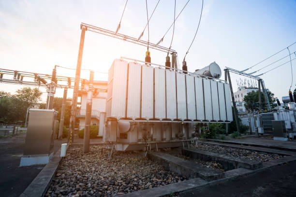
How Does the Internal Cooling System Operate in an Oil-Immersed Transformer?

In oil-immersed transformers, heat generation is unavoidable due to core losses and winding resistance during operation. If this heat is not effectively removed, it leads to insulation degradation, reduced efficiency, and potential failure. Unlike dry-type transformers that rely on air, oil-immersed transformers use a highly efficient internal cooling system based on liquid circulation. Understanding how this system operates is essential for ensuring thermal stability, long service life, and safe performance under varying load conditions.
The internal cooling system of an oil-immersed transformer operates by circulating insulating oil through natural or forced convection, where heat generated in the core and windings is absorbed by the oil, transported to cooling surfaces such as radiators, and dissipated into the surrounding environment.
This process forms a continuous thermal cycle that maintains stable operating temperatures.
Transformer oil remains stationary during operation and does not contribute to heat transfer.False
Transformer oil continuously circulates due to temperature differences, enabling efficient heat transfer and cooling.
Heat Generation Inside the Transformer
The cooling process begins with heat generation. Electrical losses in the windings and magnetic losses in the core produce thermal energy during operation.
| Heat Source | Description | Impact |
|---|---|---|
| Copper losses | Resistance in windings | Direct heat generation |
| Core losses | Eddy currents and hysteresis | Continuous heating |
| Load variation | Increased current flow | Higher temperature rise |
This heat must be removed efficiently to prevent damage.
Heat Absorption by Transformer Oil
Transformer oil surrounds all internal components and acts as a heat transfer medium. As the core and windings heat up, the oil in contact with them absorbs this thermal energy.
Q = mc\Delta T
| Oil Function | Role |
|---|---|
| Heat absorption | Removes heat from components |
| Thermal buffering | Stabilizes temperature changes |
| Energy transport | Carries heat to cooling surfaces |
Natural Convection Circulation
In most oil-immersed transformers, oil circulation occurs naturally due to temperature differences. Hot oil becomes less dense and rises, while cooler oil descends.
This creates a continuous convection loop.
| Circulation Stage | Process Description |
|---|---|
| Heating zone | Oil absorbs heat near windings |
| Rising flow | Hot oil moves upward |
| Cooling zone | Oil releases heat at radiators |
| Descending flow | Cooler oil returns downward |
This natural movement ensures continuous cooling without mechanical assistance.
Forced Oil Circulation Systems
For high-capacity transformers, natural convection may not be sufficient. In such cases, pumps are used to circulate oil more rapidly.
| Cooling Method | Description | Application |
|---|---|---|
| ONAN (Oil Natural Air Natural) | Natural oil and air cooling | Small to medium transformers |
| ONAF (Oil Natural Air Forced) | Fans enhance air cooling | Medium to high capacity |
| OFAF (Oil Forced Air Forced) | Pumps and fans used | Large power transformers |
Forced circulation improves heat transfer efficiency and supports higher load operation.
Heat Dissipation Through Radiators
After absorbing heat, the oil flows to external cooling surfaces such as radiators or fins. These components increase the surface area for heat exchange with the surrounding air.
| Cooling Component | Function |
|---|---|
| Radiators | Dissipate heat to air |
| Cooling fins | Increase surface area |
| Fans | Enhance airflow |
This step completes the heat transfer process.
Temperature Control and Monitoring
Modern transformers include temperature sensors and monitoring systems to ensure safe operation.
| Monitoring Device | Function |
|---|---|
| Winding temperature sensor | Detect internal heat |
| Oil temperature indicator | Monitor oil condition |
| Alarm system | Trigger warnings |
These systems help prevent overheating and ensure reliability.
Internal Cooling Channels and Design
Inside the transformer, special ducts and channels are designed to guide oil flow around critical components. This ensures uniform cooling and prevents hot spots.
| Design Feature | Purpose |
|---|---|
| Oil ducts | Direct oil movement |
| Cooling channels | Improve heat distribution |
| Flow optimization | Prevent localized overheating |
Real-World Engineering Example
In a high-capacity transformer operating under heavy load, insufficient oil circulation caused localized overheating in the windings. After upgrading to a forced oil circulation system with pumps and enhanced radiators, temperature distribution became uniform, and the transformer operated reliably under full load conditions.
Cooling System Performance Summary
| Cooling Aspect | Function | Benefit |
|---|---|---|
| Oil circulation | Transfers heat | Prevents overheating |
| Radiator cooling | Releases heat to environment | Maintains stable temperature |
| Monitoring system | Tracks temperature | Ensures safety |
How Does an Oil-Immersed Transformer Work Step by Step?

In modern power systems, oil-immersed transformers are essential for stepping voltage levels up or down efficiently. However, many users only understand their function at a surface level and not the internal working process. Without a clear step-by-step understanding, it becomes difficult to optimize performance, diagnose faults, or ensure safe operation. The actual process involves electromagnetic induction, magnetic flux transfer, insulation, and continuous cooling—all happening simultaneously inside a sealed tank.
An oil-immersed transformer works step by step by converting electrical energy into magnetic energy in the primary winding, transferring it through the magnetic core, inducing voltage in the secondary winding, and continuously cooling and insulating the system using circulating transformer oil.
To fully understand this process, each step must be analyzed in sequence while recognizing how electrical, magnetic, and thermal systems interact.
Energy transfer in an oil-immersed transformer occurs through direct electrical contact between windings.False
Energy is transferred through electromagnetic induction, not direct electrical contact.
Step 1: Input Electrical Energy to the Primary Winding
The process begins when alternating current is supplied to the primary winding. This current creates an alternating magnetic field around the conductor.
The magnitude of this magnetic field depends on the input voltage and current.
| Input Parameter | Effect on System |
|---|---|
| Voltage | Determines magnetic flux level |
| Current | Generates magnetic field strength |
| Frequency | Controls flux variation rate |
Step 2: Generation of Alternating Magnetic Flux
As current flows through the primary winding, it produces a time-varying magnetic field. This field is directed into the transformer core.
The changing nature of the magnetic field is essential for inducing voltage in the secondary winding.
Step 3: Magnetic Flux Transfer Through the Core
The laminated core provides a low-resistance path for magnetic flux. It ensures that most of the magnetic field is confined within the core and efficiently transferred between windings.
| Core Feature | Function |
|---|---|
| Laminated structure | Reduces energy loss |
| High permeability | Efficient flux transfer |
| Closed magnetic path | Minimizes leakage flux |
Step 4: Induction of Voltage in the Secondary Winding
The alternating magnetic flux in the core induces a voltage in the secondary winding. This is the fundamental principle of electromagnetic induction.
V_s = V_p \times \frac{N_s}{N_p}
The output voltage depends on the turns ratio between the primary and secondary windings.
| Turns Ratio Condition | Output Result |
|---|---|
| Ns > Np | Voltage is increased |
| Ns < Np | Voltage is decreased |
| Ns = Np | Voltage remains the same |
Step 5: Delivery of Electrical Energy to the Load
Once voltage is induced in the secondary winding, electrical energy is delivered to the connected load. The transformer continues to operate as long as the primary circuit is energized.
Step 6: Heat Generation During Operation
During energy transfer, losses occur in both the core and windings. These losses generate heat that must be managed to prevent damage.
| Heat Source | Description |
|---|---|
| Copper losses | Resistance in windings |
| Core losses | Eddy currents and hysteresis |
| Load variation | Increased current flow |
Step 7: Heat Absorption by Transformer Oil
The insulating oil surrounding the core and windings absorbs heat generated during operation. This prevents localized overheating and stabilizes temperature.
Q = mc\Delta T
Step 8: Oil Circulation and Cooling
The heated oil rises and flows toward cooling surfaces such as radiators. As it releases heat, it cools down and returns to absorb more heat, creating a continuous cycle.
| Cooling Stage | Process Description |
|---|---|
| Heating zone | Oil absorbs heat from windings |
| Rising flow | Hot oil moves upward |
| Cooling zone | Heat dissipates to environment |
| Return flow | Cooler oil circulates back |
Step 9: Electrical Insulation and Protection
Transformer oil and solid insulation materials prevent electrical contact between components, ensuring safe operation under high voltage conditions.
| Insulation Element | Function |
|---|---|
| Transformer oil | Electrical insulation and cooling |
| Insulation paper | Winding separation |
| Pressboard barriers | Voltage isolation |
Step 10: Continuous Monitoring and Stability
Modern transformers include monitoring systems to ensure safe operation. These systems track temperature, load, and oil condition.
| Monitoring System | Purpose |
|---|---|
| Temperature sensors | Prevent overheating |
| Oil level indicators | Ensure proper insulation |
| Protection relays | Detect faults |
Real-World Engineering Example
In a high-voltage substation, a transformer operating under heavy load maintained stable performance due to efficient oil circulation and proper insulation. When oil flow was temporarily restricted, temperature increased rapidly, highlighting the importance of the cooling cycle in continuous operation.
Step-by-Step Process Summary
| Step | Function | Outcome |
|---|---|---|
| 1 | Input electrical energy | Magnetic field generated |
| 2 | Flux creation | Magnetic energy formed |
| 3 | Core transfer | Efficient flux movement |
| 4 | Voltage induction | Output voltage generated |
| 5 | Energy delivery | Power supplied to load |
| 6 | Heat generation | Thermal energy produced |
| 7 | Oil cooling | Temperature controlled |
| 8 | Insulation | Safe operation maintained |
Conclusion
The internal structure of an oil-immersed transformer combines core, windings, insulation, and oil into an integrated system that enables efficient electromagnetic energy transfer. The core guides magnetic flux, the windings handle voltage conversion, and the oil provides both insulation and cooling. Together, these components ensure reliable operation under high voltage and heavy load conditions. A clear understanding of this structure and working process helps improve maintenance practices, enhance performance, and extend the transformer’s service life.
FAQ
Q1: What is the internal structure of an oil-immersed transformer?
An oil-immersed transformer consists of several key internal components designed to ensure efficient power transfer, insulation, and cooling:
Core: Provides a path for magnetic flux
Windings (primary and secondary): Conduct electrical current
Insulation system: Includes paper, pressboard, and oil
Transformer oil: Acts as both coolant and insulator
Tank: Houses and protects internal components
Radiators: Dissipate heat
These components work together to ensure reliable and efficient transformer operation.
Q2: How does the core function inside the transformer?
The core is made of laminated silicon steel and provides a low-reluctance path for magnetic flux. When alternating current flows through the primary winding, it generates a magnetic field in the core.
This magnetic flux links both windings and enables energy transfer through electromagnetic induction, minimizing energy losses and improving efficiency.
Q3: What role do windings play in transformer operation?
Windings are the conductive coils responsible for electrical energy transfer:
Primary winding: Receives input voltage
Secondary winding: Delivers transformed output voltage
The voltage transformation depends on the ratio of turns between the primary and secondary windings.
Q4: How does transformer oil contribute to the internal structure?
Transformer oil surrounds the core and windings, serving two essential purposes:
Insulation: Prevents electrical breakdown between components
Cooling: Absorbs heat and transfers it to radiators
The oil circulates naturally or through pumps, maintaining safe operating temperatures.
Q5: What is the function of the insulation system?
The insulation system, including paper and pressboard, ensures electrical separation between components and withstands high voltage stress.
It works together with transformer oil to provide a composite insulation system that enhances dielectric strength and reliability.
Q6: How does the cooling system work in oil-immersed transformers?
The cooling system uses oil circulation to remove heat:
Hot oil rises from the windings
It flows to radiators where heat is dissipated
Cooled oil returns to the tank
In larger transformers, fans and pumps assist this process (e.g., ONAF, OFAF cooling methods).
Q7: How does an oil-immersed transformer work overall?
The transformer operates based on electromagnetic induction:
Alternating current flows through the primary winding
A magnetic field is created in the core
This magnetic field induces voltage in the secondary winding
Electrical energy is transferred without direct electrical contact
The oil ensures safe operation by insulating and cooling the system throughout this process.
Q8: Why is this design important for power systems?
The internal structure of oil-immersed transformers is critical because it:
Ensures efficient energy transfer
Maintains thermal stability
Provides strong insulation for high voltages
Supports long service life
This design makes them essential for reliable power generation, transmission, and distribution.
References
IEC 60076 – Power Transformers
https://webstore.iec.ch/publication/602
IEC 60422 – Mineral Insulating Oils in Electrical Equipment
https://webstore.iec.ch
IEEE C57 Series – Transformer Design Standards
https://standards.ieee.org
Electrical Engineering Portal – Transformer Internal Structure Explained
https://electrical-engineering-portal.com
CIGRE – Transformer Design and Performance Studies
https://www.cigre.org
NEMA – Transformer Design Fundamentals
https://www.nema.org