Power transformers are complex electrical machines manufactured through a highly controlled process that combines precision engineering, advanced materials, and strict quality standards. From core fabrication to final testing, every stage of production directly affects transformer efficiency, reliability, and service life. Understanding how power transformers are manufactured provides insight into the technology and craftsmanship behind modern power systems.
What Raw Materials Are Used in Power Transformer Manufacturing?
Power transformers are among the most important and complex pieces of equipment used in modern electrical infrastructure. They are designed to transfer electrical energy efficiently between voltage levels while operating continuously under high electrical, thermal, and mechanical stress for decades. To achieve this reliability and performance, manufacturers carefully select specialized raw materials with precise electrical, magnetic, thermal, chemical, and mechanical properties.
The manufacturing of a power transformer involves far more than simply assembling metal and wires. Every raw material inside the transformer directly influences efficiency, dielectric strength, thermal stability, fault tolerance, operational lifespan, and environmental performance. Core materials determine magnetic losses and efficiency, winding conductors affect current carrying capability and temperature rise, insulation materials maintain dielectric integrity, and transformer oil ensures both cooling and insulation reliability.
Because modern power transformers are expected to operate safely for 25–40 years or longer, the quality and compatibility of raw materials are critical. Even small variations in material purity, insulation strength, moisture content, or thermal characteristics can significantly affect transformer reliability and operational performance.
Power transformer manufacturing uses specialized raw materials including silicon steel core laminations, copper or aluminum conductors, transformer insulation paper, pressboard, transformer oil, steel tanks, porcelain or composite bushings, insulating varnishes, cooling radiators, and structural metals designed to provide electrical insulation, magnetic efficiency, thermal stability, and mechanical strength.
These materials work together as a highly integrated electrical and thermal system to ensure long-term transformer performance and reliability.
Ordinary industrial metals and standard insulation materials are sufficient for manufacturing high-voltage power transformers.False
Power transformers require highly specialized magnetic, conductive, insulating, and thermal materials engineered specifically for high-voltage, high-temperature, and long-term electrical operation.
Why Raw Material Selection Is Critical
Power transformers operate under severe operating conditions.
Main Operating Stresses
| Stress Type | Transformer Impact |
|---|---|
| High voltage | Dielectric stress |
| High current | Thermal heating |
| Electromagnetic forces | Mechanical stress |
| Environmental exposure | Material aging |
Raw materials must withstand all of these conditions simultaneously.
Magnetic Core Materials
The transformer core is one of the most important components.
Main Function of the Core
The magnetic core provides a low-reluctance path for magnetic flux.
Electromagnetic Induction Principle
E=4.44fN\Phi
The core helps transfer magnetic energy efficiently between windings.
Silicon Steel Core Laminations
Most power transformer cores use grain-oriented silicon steel.
Why Silicon Steel Is Used
| Property | Benefit |
|---|---|
| High magnetic permeability | Efficient flux transfer |
| Low hysteresis loss | Reduced heating |
| High resistivity | Lower eddy current loss |
Core Loss Mechanisms
Main Core Losses
| Loss Type | Cause |
|---|---|
| Hysteresis loss | Magnetic domain switching |
| Eddy current loss | Induced circulating currents |
High-quality silicon steel minimizes these losses.
Amorphous Metal Core Materials
Some high-efficiency transformers use amorphous metal cores.
Advantages of Amorphous Metal
| Feature | Benefit |
|---|---|
| Extremely low core loss | Higher efficiency |
| Thin ribbon structure | Reduced eddy currents |
These materials are commonly used in energy-efficient distribution transformers.
Winding Conductor Materials
Transformer windings carry electrical current.
Main Conductor Materials
| Material | Application |
|---|---|
| Copper | High-efficiency transformers |
| Aluminum | Lower-cost designs |
Why Copper Is Widely Used
Copper provides excellent electrical conductivity and mechanical strength.
Copper Advantages
| Property | Benefit |
|---|---|
| High conductivity | Reduced losses |
| Mechanical strength | Better short-circuit resistance |
| Thermal conductivity | Improved heat transfer |
Transformer Copper Loss
P_{cu}=I^2R
Lower conductor resistance reduces copper losses and heating.
Aluminum Conductors
Aluminum is sometimes used to reduce cost and weight.
Aluminum Characteristics
| Feature | Effect |
|---|---|
| Lower density | Reduced transformer weight |
| Lower conductivity | Larger conductor size required |
Insulation Materials
Transformer insulation systems are extremely important.
Main Insulation Functions
| Function | Purpose |
|---|---|
| Electrical isolation | Prevent short circuits |
| Thermal stability | Withstand operating heat |
| Mechanical support | Maintain winding structure |
Cellulose Insulation Paper
Most transformer winding insulation uses cellulose paper.
Why Cellulose Is Used
| Property | Benefit |
|---|---|
| High dielectric strength | Excellent insulation |
| Oil compatibility | Stable oil-paper system |
| Flexibility | Easy winding application |
Pressboard Insulation
Pressboard is used for structural insulation support.
Pressboard Applications
| Application | Purpose |
|---|---|
| Spacer blocks | Oil flow channels |
| Barrier insulation | Voltage separation |
| Structural support | Mechanical stability |
Transformer Oil
Transformer oil performs both cooling and insulation functions.
Main Oil Functions
| Function | Importance |
|---|---|
| Dielectric insulation | Prevent electrical breakdown |
| Heat transfer | Cooling performance |
| Arc suppression | Fault protection |
Types of Transformer Oil
| Oil Type | Characteristics |
|---|---|
| Mineral oil | Standard industrial use |
| Natural ester | Biodegradable |
| Synthetic ester | Higher fire resistance |
Thermal Management Materials
Power transformers require effective cooling systems.
Cooling Components
| Component | Function |
|---|---|
| Radiators | Heat dissipation |
| Cooling fans | Forced air circulation |
| Oil pumps | Forced oil circulation |
Transformer Tank Materials
Transformer tanks provide structural protection.
Tank Material Requirements
| Property | Importance |
|---|---|
| Mechanical strength | Pressure resistance |
| Corrosion resistance | Long service life |
| Weldability | Manufacturing reliability |
Most tanks are fabricated from carbon steel plates.
Bushings and External Insulation
Bushings allow conductors to pass safely through grounded transformer tanks.
Bushing Materials
| Material | Application |
|---|---|
| Porcelain | Traditional high-voltage bushings |
| Composite polymer | Lightweight modern designs |
Why Bushings Are Important
Bushings must withstand:
- High voltage stress
- Environmental contamination
- Thermal expansion
- Mechanical vibration
Structural Steel Components
Transformers also contain many structural metal components.
Structural Components
| Component | Function |
|---|---|
| Clamping frames | Core compression |
| Support brackets | Mechanical stability |
| Fasteners | Structural assembly |
These components help withstand short-circuit forces.
Electromagnetic Fault Forces
F ∝ I²
Fault currents can generate enormous mechanical stress inside transformers.
Insulating Varnishes and Coatings
Various protective coatings are used throughout transformer manufacturing.
Coating Applications
| Coating Type | Function |
|---|---|
| Insulating varnish | Surface insulation |
| Anti-corrosion coating | Environmental protection |
| Epoxy resin | Mechanical reinforcement |
Sealing Materials and Gaskets
Transformers require leak-proof sealing systems.
Common Sealing Materials
| Material | Purpose |
|---|---|
| Nitrile rubber | Oil sealing |
| Silicone gaskets | High-temperature sealing |
Cooling System Metals
Radiators and cooling structures require thermally conductive materials.
Common Cooling Materials
| Material | Benefit |
|---|---|
| Steel radiators | Durable heat dissipation |
| Copper tubing | High thermal conductivity |
Environmental and Fire-Safety Materials
Modern transformer design increasingly emphasizes environmental protection.
Eco-Friendly Materials
| Material | Benefit |
|---|---|
| Biodegradable ester fluids | Reduced environmental impact |
| Fire-resistant insulation | Improved safety |
Material Purity and Quality Control
Transformer materials must meet extremely strict quality standards.
Why Purity Matters
| Contamination Type | Risk |
|---|---|
| Moisture | Reduced dielectric strength |
| Metallic particles | Partial discharge |
| Chemical impurities | Accelerated aging |
Real-World Manufacturing Example
A 220 kV utility transformer may contain:
| Material | Approximate Quantity |
|---|---|
| Silicon steel core | Several tons |
| Copper conductors | Multiple tons |
| Transformer oil | Thousands of liters |
| Cellulose insulation | Hundreds of kilograms |
Material quality directly determines transformer reliability.
Key Raw Materials Used in Power Transformer Manufacturing
| Material Category | Main Function |
|---|---|
| Silicon steel | Magnetic flux transfer |
| Copper/aluminum | Current conduction |
| Cellulose insulation | Dielectric insulation |
| Pressboard | Structural insulation |
| Transformer oil | Cooling and insulation |
| Steel tank | Mechanical protection |
| Bushings | High-voltage conductor insulation |
| Coatings and sealants | Environmental protection |
How Are Transformer Cores and Windings Produced?
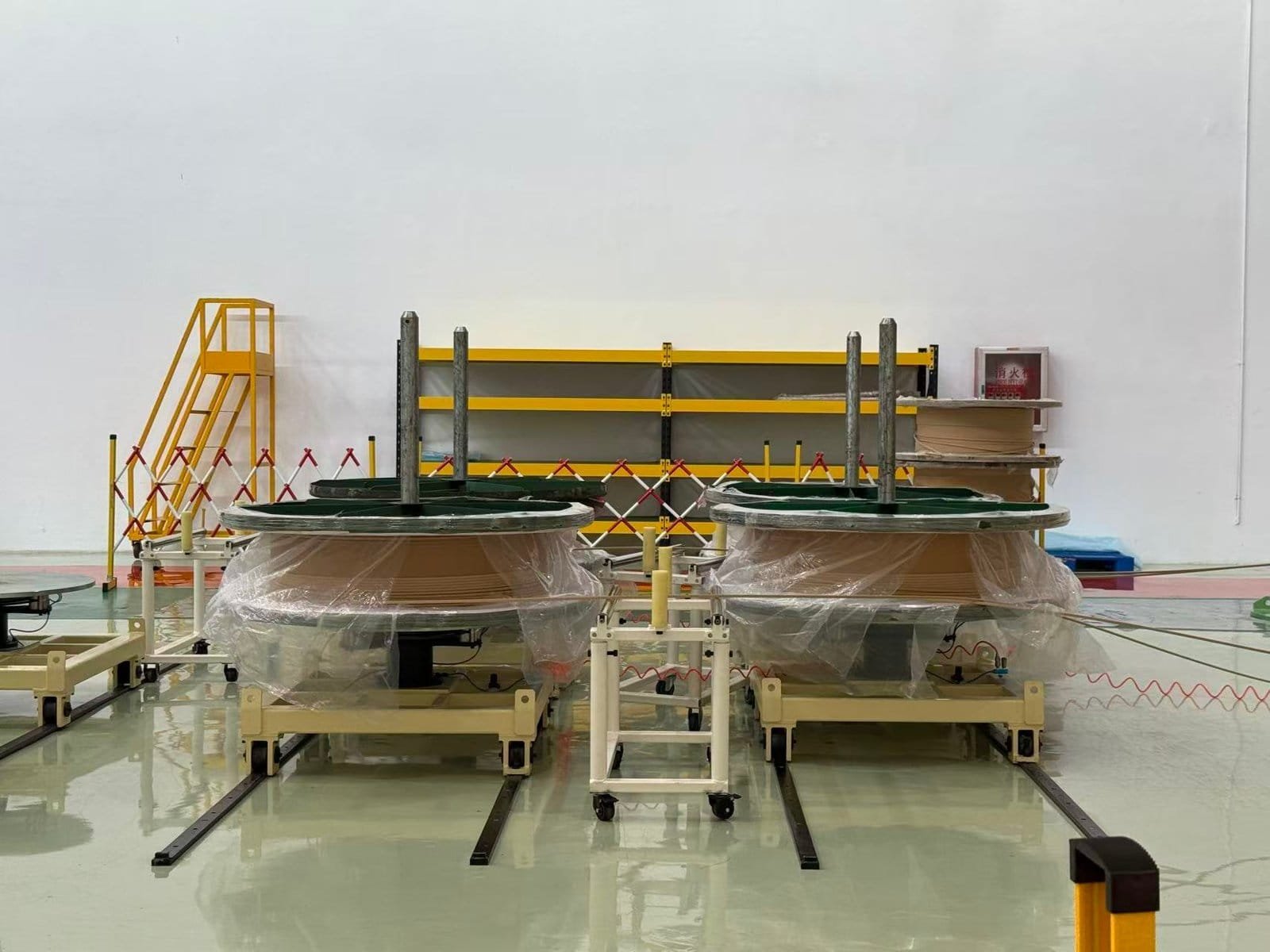
Transformer cores and windings are the two most important active components inside a power transformer. Together, they form the electromagnetic system responsible for transferring electrical energy efficiently between voltage levels. The transformer core provides a controlled magnetic flux path, while the windings carry electrical current and create electromagnetic induction. Because transformers operate continuously under high electrical, thermal, and mechanical stress, the production of cores and windings requires extremely precise engineering, specialized materials, advanced manufacturing technology, and strict quality control.
Modern transformer manufacturing is a highly sophisticated industrial process involving magnetic material processing, conductor forming, insulation application, mechanical assembly, vacuum drying, and electrical testing. Even small deviations in core alignment, winding geometry, insulation spacing, or conductor tension can significantly affect transformer efficiency, temperature rise, noise levels, dielectric strength, and fault tolerance.
Core and winding production is therefore not simply a mechanical assembly process—it is a carefully controlled electromagnetic engineering operation designed to maximize efficiency, minimize losses, ensure dielectric reliability, and guarantee long-term operational stability.
Transformer cores are produced by cutting, stacking, and clamping thin silicon steel laminations to form a low-loss magnetic circuit, while transformer windings are manufactured by precisely winding insulated copper or aluminum conductors around the core using specialized winding machines, insulation systems, and mechanical reinforcement techniques.
The interaction between the core and windings ultimately determines transformer efficiency, voltage transformation capability, thermal behavior, and short-circuit performance.
Transformer cores and windings are simple metal components that require only basic industrial fabrication processes.False
Transformer cores and windings require highly specialized electromagnetic design, precision manufacturing, insulation engineering, and strict quality control to ensure efficiency, reliability, and long-term performance.
Why Core and Winding Manufacturing Is Critical
Transformer performance depends heavily on the precision of its active parts.
Main Performance Factors
| Component | Main Influence |
|---|---|
| Core | Magnetic efficiency |
| Windings | Current carrying capability |
| Insulation | Dielectric reliability |
| Mechanical assembly | Short-circuit strength |
Poor manufacturing quality can cause overheating, vibration, partial discharge, or catastrophic failure.
Transformer Core Production
Function of the Transformer Core
The transformer core provides a low-reluctance magnetic path for flux transfer.
Electromagnetic Induction Principle
E=4.44fN\Phi
The magnetic core allows efficient energy transfer between windings by concentrating magnetic flux.
Raw Materials for Transformer Cores
Most transformer cores use grain-oriented silicon steel.
Why Silicon Steel Is Used
| Property | Engineering Benefit |
|---|---|
| High magnetic permeability | Efficient flux conduction |
| Low hysteresis loss | Reduced heating |
| High resistivity | Lower eddy current loss |
Silicon Steel Lamination Production
Transformer cores are not made from solid steel blocks.
Why Laminations Are Necessary
Thin laminations reduce eddy current losses.
Eddy Current Loss Relationship
P_e ∝ B²f²t²
Where:
- (B) = magnetic flux density
- (f) = frequency
- (t) = lamination thickness
Reducing lamination thickness lowers eddy current heating.
Core Cutting Process
Silicon steel sheets are precision cut into specific shapes.
Core Cutting Technologies
| Method | Application |
|---|---|
| CNC cutting | High precision laminations |
| Step-lap cutting | Reduced noise and losses |
| Automated punching | Mass production |
Precision cutting is critical for magnetic alignment.
Step-Lap Core Design
Modern transformers often use step-lap core joints.
Advantages of Step-Lap Joints
| Benefit | Result |
|---|---|
| Reduced magnetic gap | Lower losses |
| Lower vibration | Reduced noise |
| Improved flux continuity | Higher efficiency |
Core Stacking Process
After cutting, laminations are stacked carefully.
Core Stacking Objectives
| Objective | Purpose |
|---|---|
| Precise alignment | Uniform magnetic path |
| Tight compression | Reduced vibration |
| Correct orientation | Optimal magnetic performance |
Improper stacking can increase losses and noise.
Core Clamping and Assembly
The completed core must be mechanically stabilized.
Why Clamping Is Necessary
| Problem Prevented | Benefit |
|---|---|
| Lamination vibration | Lower noise |
| Core displacement | Improved reliability |
| Mechanical stress | Better fault tolerance |
Core Annealing Process
Some cores undergo heat treatment after cutting.
Purpose of Annealing
| Benefit | Result |
|---|---|
| Relieves mechanical stress | Improved magnetic properties |
| Restores grain orientation | Lower core losses |
Transformer Winding Production
Function of Transformer Windings
Windings carry electrical current and create electromagnetic induction.
Main Winding Types
| Winding | Function |
|---|---|
| Primary winding | Receives input energy |
| Secondary winding | Delivers transformed output |
Conductor Materials
Windings are typically made from copper or aluminum.
Copper vs Aluminum
| Property | Copper | Aluminum |
|---|---|---|
| Conductivity | Higher | Lower |
| Mechanical strength | Higher | Lower |
| Weight | Heavier | Lighter |
Copper is preferred for high-performance transformers.
Winding Conductor Shapes
Different conductor shapes are used depending on transformer design.
Common Conductor Types
| Conductor Type | Application |
|---|---|
| Round wire | Small transformers |
| Rectangular conductor | Large power transformers |
| Continuously transposed conductor (CTC) | High-current applications |
Insulation Application
Conductors are insulated before winding.
Insulation Materials
| Material | Purpose |
|---|---|
| Enamel coating | Basic conductor insulation |
| Cellulose paper | Dielectric reinforcement |
| Epoxy systems | Additional protection |
Winding Production Process
Specialized winding machines produce transformer coils.
Main Winding Steps
| Step | Function |
|---|---|
| Conductor tension control | Uniform winding |
| Layer insulation placement | Dielectric separation |
| Coil shaping | Mechanical stability |
Precision is extremely important during winding.
Winding Configurations
Different transformer applications use different winding structures.
Common Winding Designs
| Winding Type | Characteristics |
|---|---|
| Cylindrical winding | Simple structure |
| Disc winding | High-voltage transformers |
| Helical winding | High-current transformers |
Mechanical Reinforcement of Windings
Windings must withstand enormous electromagnetic forces during faults.
Electromagnetic Force Relationship
F ∝ I²
Short-circuit currents can generate very high mechanical stress.
Reinforcement Methods
| Method | Purpose |
|---|---|
| Spacer blocks | Mechanical support |
| Clamping structures | Coil stabilization |
| Epoxy bonding | Vibration resistance |
Insulation Between Windings
High-voltage transformers require complex insulation systems.
Insulation Components
| Component | Function |
|---|---|
| Pressboard barriers | Voltage separation |
| Oil ducts | Cooling flow |
| Spacer insulation | Mechanical stability |
Drying and Vacuum Processing
Moisture is extremely dangerous inside transformers.
Why Drying Is Critical
| Moisture Effect | Consequence |
|---|---|
| Reduced dielectric strength | Breakdown risk |
| Partial discharge | Insulation aging |
Vacuum Drying Process
Transformers undergo vacuum drying before oil filling.
Vacuum Drying Objectives
| Objective | Result |
|---|---|
| Remove moisture | Improved insulation |
| Eliminate trapped gases | Better dielectric stability |
Core and Coil Assembly
After core and winding production, components are assembled together.
Assembly Objectives
| Objective | Purpose |
|---|---|
| Correct winding alignment | Uniform magnetic coupling |
| Proper insulation spacing | Dielectric safety |
| Structural stability | Fault resistance |
Oil Impregnation Process
Oil-filled transformers undergo vacuum oil impregnation.
Why Oil Impregnation Is Important
| Benefit | Result |
|---|---|
| Eliminates air voids | Reduced partial discharge |
| Improves insulation | Higher dielectric strength |
| Enhances cooling | Better thermal performance |
Quality Control and Testing
Core and winding production requires extensive testing.
Common Manufacturing Tests
| Test | Purpose |
|---|---|
| Turns ratio test | Voltage verification |
| Insulation resistance test | Dielectric integrity |
| Winding resistance test | Conductor quality |
| Partial discharge test | Insulation reliability |
Real-World Manufacturing Example
A large 400 kV power transformer may contain:
| Component | Approximate Specification |
|---|---|
| Silicon steel laminations | Several tons |
| Copper windings | Multiple winding layers |
| Insulation paper | Hundreds of kilograms |
| Vacuum drying cycle | Several days |
Precision manufacturing directly affects transformer lifespan and efficiency.
Key Manufacturing Stages for Transformer Cores and Windings
| Manufacturing Stage | Main Purpose |
|---|---|
| Core cutting | Magnetic path optimization |
| Lamination stacking | Loss reduction |
| Winding production | Electrical energy transfer |
| Insulation application | Dielectric safety |
| Vacuum drying | Moisture removal |
| Core-coil assembly | Electromagnetic stability |
How Is the Insulation System Assembled and Processed?
The insulation system is one of the most critical parts of a power transformer because it determines the transformer’s dielectric strength, thermal endurance, operational reliability, and service lifespan. While transformer cores and windings handle magnetic flux and electrical current, the insulation system ensures that different energized components remain electrically isolated under extremely high voltages and harsh thermal conditions. In high-voltage and extra-high-voltage transformers, insulation failure is one of the most dangerous and costly failure mechanisms, which is why insulation assembly and processing require extraordinary precision, cleanliness, moisture control, and engineering expertise.
Transformer insulation systems are not composed of a single material. Instead, they are highly integrated dielectric structures made from cellulose paper, pressboard, insulating oil, spacers, barriers, varnishes, epoxy systems, and air or oil ducts. These materials work together to withstand electrical stress, thermal aging, moisture exposure, mechanical vibration, and electromagnetic forces during normal operation and fault conditions.
The insulation assembly process involves multiple stages including material preparation, conductor insulation wrapping, spacer installation, winding insulation coordination, core-coil assembly, vacuum drying, oil impregnation, and dielectric testing. Every stage must be tightly controlled because even microscopic contamination, trapped moisture, improper spacing, or air voids can lead to partial discharge, insulation degradation, electrical breakdown, or catastrophic transformer failure.
Transformer insulation systems are assembled and processed by carefully applying cellulose insulation materials, pressboard barriers, spacers, and dielectric structures around transformer windings and cores, followed by vacuum drying, moisture removal, oil impregnation, and dielectric testing to ensure long-term electrical insulation reliability and thermal stability.
The insulation system therefore acts as the transformer’s primary electrical protection structure and is essential for safe long-term operation.
Transformer insulation systems are simple protective layers that can tolerate small amounts of moisture or assembly contamination without major performance impact.False
Transformer insulation systems require extremely precise assembly, moisture control, and cleanliness because even minor contamination or moisture can significantly reduce dielectric strength and accelerate insulation failure.
Why Transformer Insulation Systems Are Critical
Transformer insulation systems must withstand multiple operating stresses simultaneously.
Main Insulation Challenges
| Operating Stress | Insulation Impact |
|---|---|
| High voltage | Dielectric stress |
| Thermal heating | Insulation aging |
| Moisture contamination | Reduced dielectric strength |
| Electromagnetic forces | Mechanical stress |
| Partial discharge | Insulation erosion |
The insulation system must remain stable under all these conditions for decades.
Main Components of Transformer Insulation Systems
Cellulose Insulation Paper
Cellulose paper is one of the most widely used transformer insulation materials.
Why Cellulose Paper Is Used
| Property | Benefit |
|---|---|
| High dielectric strength | Excellent insulation |
| Flexibility | Easy conductor wrapping |
| Oil compatibility | Stable oil-paper insulation system |
Cellulose paper is typically wrapped directly around conductors.
Pressboard Insulation
Pressboard is a thicker cellulose-based insulating material.
Functions of Pressboard
| Application | Purpose |
|---|---|
| Barrier insulation | Voltage separation |
| Spacer blocks | Oil flow channels |
| Mechanical support | Winding stability |
Pressboard structures are essential in high-voltage transformers.
Transformer Oil as Part of the Insulation System
Transformer oil is a major dielectric component.
Oil Functions
| Function | Purpose |
|---|---|
| Dielectric insulation | Prevent electrical breakdown |
| Heat transfer | Cooling performance |
| Void elimination | Reduced partial discharge |
The oil-paper insulation system is the foundation of oil-filled transformer design.
Conductor Insulation Assembly
Insulating the Conductors
Before winding production, conductors are insulated carefully.
Conductor Insulation Materials
| Material | Function |
|---|---|
| Enamel coating | Basic conductor insulation |
| Cellulose wrapping | Additional dielectric strength |
| Epoxy coating | Mechanical reinforcement |
Insulation Wrapping Process
Specialized machines wrap insulation around conductors.
Why Precision Wrapping Matters
| Problem Prevented | Benefit |
|---|---|
| Uneven insulation thickness | Stable dielectric spacing |
| Air gaps | Reduced partial discharge |
| Loose insulation | Better mechanical stability |
Winding Insulation Assembly
Layer-to-Layer Insulation
Each winding layer must be electrically isolated.
Layer Insulation Components
| Component | Purpose |
|---|---|
| Insulation paper | Dielectric separation |
| Pressboard strips | Mechanical spacing |
| Oil ducts | Cooling flow channels |
Inter-Winding Insulation
High-voltage transformers require insulation between windings.
Inter-Winding Insulation Requirements
| Requirement | Importance |
|---|---|
| Voltage withstand capability | Prevent breakdown |
| Mechanical rigidity | Fault resistance |
| Thermal stability | Long service life |
Barrier Insulation Structures
Barrier insulation controls electric field distribution.
Why Barriers Are Necessary
| Benefit | Result |
|---|---|
| Uniform electric fields | Reduced stress concentration |
| Increased dielectric path length | Higher insulation strength |
Electric Field Control in Transformer Insulation
Electric field management is a major insulation design objective.
Electric Stress Relationship
E=\frac{V}{d}
Where:
- (E) = electric field intensity
- (V) = voltage
- (d) = insulation distance
Improper spacing can create dangerous stress concentrations.
Spacer and Oil Duct Assembly
Purpose of Spacers
Spacers maintain insulation distance and cooling flow.
Spacer Functions
| Function | Benefit |
|---|---|
| Mechanical support | Winding stability |
| Oil flow guidance | Improved cooling |
| Dielectric separation | Electrical insulation |
Oil Duct Design
Transformer oil must circulate freely through windings.
Why Oil Ducts Matter
| Benefit | Result |
|---|---|
| Better heat dissipation | Reduced hot spots |
| Uniform temperature distribution | Longer insulation life |
Core-to-Winding Insulation
The transformer core must be insulated from the windings.
Core Insulation Functions
| Function | Purpose |
|---|---|
| Prevent grounding faults | Electrical safety |
| Reduce eddy currents | Lower losses |
| Stabilize insulation structure | Mechanical reliability |
Mechanical Reinforcement of Insulation Systems
Transformer insulation systems must withstand fault forces.
Electromagnetic Force Relationship
F ∝ I²
Short-circuit currents can generate enormous mechanical stress.
Mechanical Support Structures
| Structure | Function |
|---|---|
| Clamping systems | Winding stabilization |
| Pressboard supports | Structural rigidity |
| Spacer blocks | Compression control |
Cleanroom and Contamination Control
Insulation assembly requires extremely clean conditions.
Why Cleanliness Is Critical
| Contaminant | Risk |
|---|---|
| Dust particles | Partial discharge initiation |
| Metal particles | Electrical breakdown |
| Moisture | Dielectric degradation |
Even microscopic contamination can reduce insulation reliability.
Moisture Control During Assembly
Moisture is one of the greatest threats to transformer insulation.
Why Moisture Is Dangerous
| Moisture Effect | Consequence |
|---|---|
| Reduced dielectric strength | Breakdown risk |
| Cellulose hydrolysis | Accelerated aging |
| Partial discharge increase | Insulation erosion |
Insulation Drying Before Assembly
Insulation materials are dried before installation.
Drying Objectives
| Objective | Result |
|---|---|
| Remove absorbed water | Improved dielectric strength |
| Stabilize materials | Better reliability |
Vacuum Drying Process
After assembly, transformers undergo vacuum drying.
Why Vacuum Drying Is Necessary
| Benefit | Purpose |
|---|---|
| Removes trapped moisture | Higher insulation reliability |
| Eliminates gases | Reduced discharge activity |
Vacuum Drying Procedure
Main Vacuum Drying Stages
| Stage | Function |
|---|---|
| Heating | Moisture evaporation |
| Vacuum application | Moisture extraction |
| Stabilization | Insulation conditioning |
Vacuum drying may last several days for large transformers.
Oil Impregnation Process
Oil impregnation is a critical final stage.
Purpose of Oil Impregnation
| Function | Benefit |
|---|---|
| Fill microscopic voids | Reduced partial discharge |
| Improve cooling | Better thermal transfer |
| Increase dielectric strength | Higher voltage withstand capability |
Vacuum Oil Filling
Transformers are often filled with oil under vacuum conditions.
Why Vacuum Filling Is Important
| Benefit | Result |
|---|---|
| Eliminates trapped air | Improved dielectric stability |
| Uniform oil penetration | Better insulation performance |
Thermal Stability of Insulation Systems
Transformer insulation must withstand long-term heating.
Transformer Thermal Aging Relationship
Higher operating temperatures dramatically reduce insulation lifespan.
Dielectric Testing After Assembly
Insulation systems undergo extensive testing before shipment.
Common Dielectric Tests
| Test | Purpose |
|---|---|
| Insulation resistance test | Detect contamination |
| Partial discharge test | Verify insulation quality |
| Power frequency withstand test | High-voltage verification |
| Impulse test | Lightning surge resistance |
Real-World Manufacturing Example
A large 400 kV transformer insulation system may include:
| Component | Approximate Quantity |
|---|---|
| Cellulose insulation paper | Hundreds of kilograms |
| Pressboard barriers | Large multilayer structures |
| Vacuum drying time | Several days |
| Oil impregnation volume | Thousands of liters |
Even small insulation defects can affect long-term reliability.
Key Stages of Transformer Insulation Assembly and Processing
| Manufacturing Stage | Main Objective |
|---|---|
| Conductor insulation | Dielectric separation |
| Barrier assembly | Electric field control |
| Spacer installation | Cooling and support |
| Vacuum drying | Moisture removal |
| Oil impregnation | Dielectric stabilization |
| Dielectric testing | Quality verification |
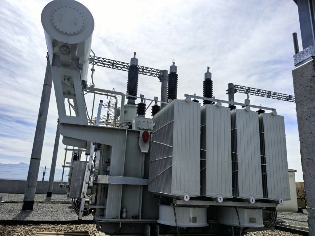
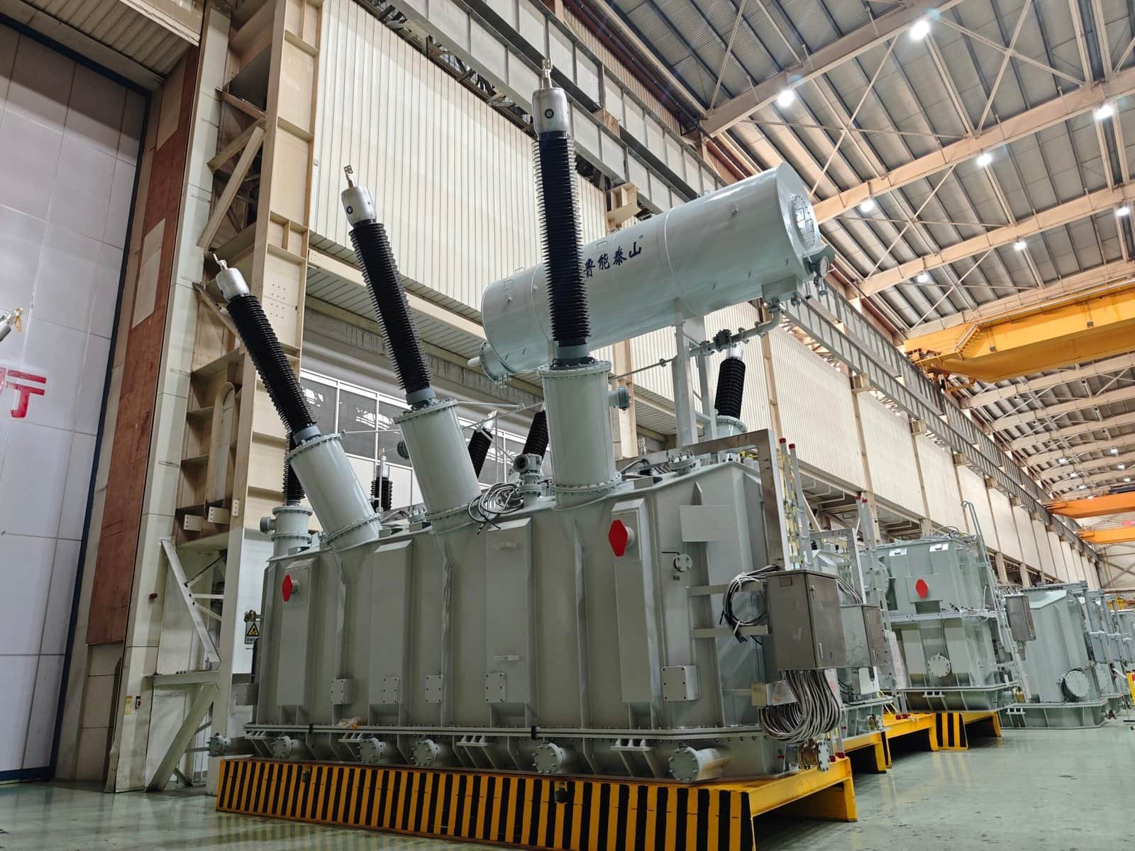
What Role Do Tank Fabrication and Cooling Components Play?
Tank fabrication and cooling component design are fundamental aspects of power transformer manufacturing because they directly influence transformer reliability, thermal performance, mechanical strength, environmental protection, operational safety, and service lifespan. While transformer cores and windings perform electromagnetic energy transfer, the transformer tank and cooling system create the physical and thermal environment necessary for stable long-term operation under high electrical and thermal stress.
A power transformer continuously generates heat due to copper losses, core losses, stray losses, and magnetic leakage flux. If this heat is not removed effectively, internal temperatures rise rapidly, accelerating insulation aging, reducing dielectric strength, increasing mechanical stress, and potentially causing catastrophic failure. The transformer tank and cooling components therefore serve as the primary thermal management structure of the transformer.
In addition to cooling, the transformer tank provides mechanical protection, oil containment, environmental sealing, structural stability, short-circuit force resistance, and transportation durability. Modern transformer tanks are highly engineered pressure-resistant steel structures designed to withstand thermal expansion, vacuum conditions, seismic stress, oil pressure fluctuations, and fault-generated mechanical forces over decades of operation.
Transformer tank fabrication and cooling components play critical roles in providing structural protection, oil containment, heat dissipation, mechanical stability, environmental sealing, and thermal management to ensure safe, efficient, and reliable long-term transformer operation.
The quality of tank fabrication and cooling system engineering directly affects transformer efficiency, insulation lifespan, maintenance requirements, and operational reliability.
Transformer tanks mainly function as simple outer containers and have little influence on transformer performance or reliability.False
Transformer tanks and cooling systems are essential for heat dissipation, insulation protection, structural stability, oil containment, and long-term transformer reliability.
Why Transformer Tanks and Cooling Systems Are Essential
Power transformers generate continuous heat during operation.
Main Sources of Transformer Heat
| Heat Source | Cause |
|---|---|
| Copper losses | Winding resistance |
| Core losses | Magnetic hysteresis and eddy currents |
| Stray losses | Leakage flux heating |
Without effective cooling, transformer temperatures would rise to destructive levels.
Transformer Heating Mechanisms
Copper Loss Heating
Electrical current flowing through windings generates resistive heat.
Copper Loss Equation
P_{cu}=I^2R
As transformer load current increases, heat generation rises significantly.
Core Loss Heating
The transformer core also generates continuous heat.
Main Core Losses
| Core Loss Type | Cause |
|---|---|
| Hysteresis loss | Magnetic domain switching |
| Eddy current loss | Induced circulating currents |
These losses exist whenever the transformer is energized.
Role of Transformer Tank Fabrication
Structural Protection Function
The transformer tank protects internal active components.
Components Protected by the Tank
| Internal Component | Protection Purpose |
|---|---|
| Core | Mechanical stability |
| Windings | Environmental isolation |
| Insulation system | Moisture prevention |
| Transformer oil | Leak containment |
Mechanical Strength Requirements
Transformer tanks must withstand severe operating conditions.
Main Mechanical Stresses
| Stress Type | Source |
|---|---|
| Oil pressure | Thermal expansion |
| Vacuum stress | Oil processing |
| Transportation shock | Logistics handling |
| Short-circuit forces | Electromagnetic events |
Electromagnetic Fault Forces
F ∝ I²
Fault currents can generate enormous mechanical stress inside transformers.
Tank Material Selection
Transformer tanks are usually fabricated from carbon steel.
Why Carbon Steel Is Commonly Used
| Property | Benefit |
|---|---|
| High mechanical strength | Structural durability |
| Weldability | Reliable fabrication |
| Cost effectiveness | Industrial practicality |
Corrosion Resistance Requirements
Transformer tanks operate in harsh environments.
Environmental Exposure Risks
| Environmental Condition | Potential Damage |
|---|---|
| Humidity | Corrosion |
| Salt contamination | Surface degradation |
| Industrial pollution | Chemical attack |
Protective coatings are therefore essential.
Tank Fabrication Process
Steel Plate Preparation
Tank fabrication begins with heavy steel plate processing.
Main Fabrication Steps
| Manufacturing Step | Purpose |
|---|---|
| Cutting | Dimensional accuracy |
| Bending | Structural shaping |
| Welding | Mechanical assembly |
Precision Welding Operations
Transformer tanks require high-quality welding.
Why Welding Quality Is Critical
| Poor Welding Risk | Consequence |
|---|---|
| Oil leakage | Insulation contamination |
| Structural weakness | Mechanical failure |
| Crack formation | Reduced lifespan |
Tank Sealing and Leak Prevention
Oil containment reliability is essential.
Common Sealing Components
| Component | Function |
|---|---|
| Gaskets | Leak prevention |
| Flanges | Mechanical sealing |
| Weld joints | Structural integrity |
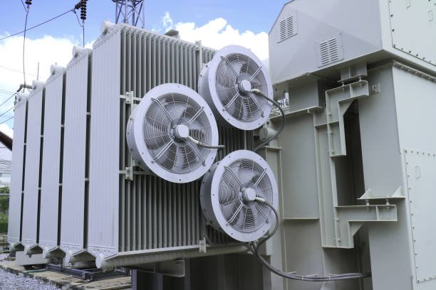
Role of Transformer Cooling Components
Cooling systems maintain safe operating temperature.
Why Cooling Is Necessary
Transformer insulation lifespan depends heavily on temperature.
Main Cooling Components in Power Transformers
Cooling Radiators
Radiators are the primary heat dissipation components.
How Radiators Work
| Cooling Step | Function |
|---|---|
| Heat transfer to oil | Internal heat absorption |
| Oil circulation to radiator | Heat transport |
| Heat release to air | Thermal dissipation |
Radiator Design Considerations
| Design Factor | Importance |
|---|---|
| Surface area | Heat transfer efficiency |
| Oil flow capacity | Cooling performance |
| Mechanical strength | Long-term durability |
Cooling Fans
Large transformers often use forced-air cooling.
Function of Cooling Fans
| Fan Function | Benefit |
|---|---|
| Increase airflow | Faster heat removal |
| Improve radiator efficiency | Lower operating temperature |
Forced Cooling Systems
Common Cooling Modes
| Cooling Method | Description |
|---|---|
| ONAN | Oil Natural Air Natural |
| ONAF | Oil Natural Air Forced |
| OFAF | Oil Forced Air Forced |
Oil Pumps
Some large transformers use forced oil circulation.
Purpose of Oil Pumps
| Function | Benefit |
|---|---|
| Faster oil circulation | Improved cooling |
| Reduced hot spots | Better thermal distribution |
Conservator Tanks
Many transformers use conservator systems.
Function of Conservators
| Function | Purpose |
|---|---|
| Oil expansion accommodation | Pressure stabilization |
| Reduced oil oxidation | Improved oil lifespan |
Breather Systems
Breathers control moisture ingress.
Why Breathers Are Important
| Problem Prevented | Benefit |
|---|---|
| Moisture contamination | Improved insulation reliability |
| Oil degradation | Longer service life |
Silica gel breathers are commonly used.
Thermal Expansion Management
Transformer oil expands during heating.
Why Expansion Compensation Is Necessary
| Problem | Consequence |
|---|---|
| Oil expansion pressure | Tank stress |
| Vacuum formation during cooling | Structural deformation |
Tank design must accommodate thermal movement.
Pressure Relief and Safety Components
Transformers require fault protection systems.
Main Safety Devices
| Device | Function |
|---|---|
| Pressure relief valve | Prevent tank rupture |
| Buchholz relay | Gas fault detection |
| Sudden pressure relay | Internal fault protection |
Cooling Performance and Transformer Efficiency
Efficient cooling improves transformer reliability.
Temperature Rise Effects
| Temperature Increase | Impact |
|---|---|
| Higher winding temperature | Faster insulation aging |
| Increased resistance | Higher copper losses |
| Oil degradation | Reduced dielectric strength |
Hot Spot Prevention
Cooling systems help eliminate dangerous hot spots.
Why Hot Spots Are Dangerous
| Hot Spot Effect | Consequence |
|---|---|
| Cellulose degradation | Reduced insulation lifespan |
| Carbonization | Electrical tracking |
| Thermal stress | Mechanical damage |
Noise and Vibration Reduction
Transformer tanks also influence acoustic performance.
Sources of Transformer Noise
| Source | Cause |
|---|---|
| Core vibration | Magnetostriction |
| Cooling fans | Air movement |
| Oil circulation | Hydraulic flow |
Tank rigidity helps reduce vibration.
Transportation and Installation Requirements
Large power transformers experience significant transportation stress.
Transportation Challenges
| Challenge | Engineering Requirement |
|---|---|
| Vibration | Structural reinforcement |
| Lifting stress | Mechanical support |
| Seismic loading | Stability design |
Environmental Protection Role
Transformer tanks also provide environmental protection.
Environmental Safety Functions
| Function | Benefit |
|---|---|
| Oil containment | Pollution prevention |
| Fire risk management | Operational safety |
| Corrosion protection | Extended service life |
Real-World Manufacturing Example
A large 400 kV power transformer may include:
| Component | Approximate Specification |
|---|---|
| Steel tank weight | Tens of tons |
| Cooling radiators | Multiple large panels |
| Oil volume | Thousands of liters |
| Cooling fans | Several forced-air units |
Tank and cooling system quality strongly influence transformer lifespan.
Key Functions of Tank Fabrication and Cooling Components
| Component/System | Main Function |
|---|---|
| Transformer tank | Structural protection |
| Radiators | Heat dissipation |
| Cooling fans | Forced air cooling |
| Oil pumps | Oil circulation |
| Conservator | Oil expansion control |
| Breathers | Moisture prevention |
| Safety valves | Pressure protection |
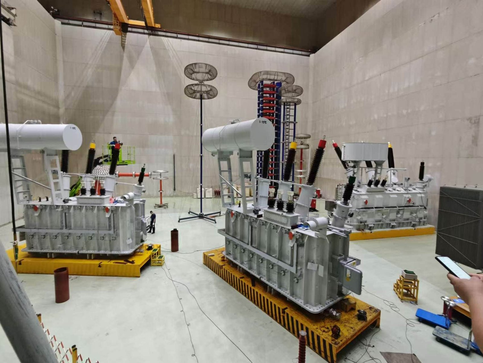
How Are Vacuum Drying, Oil Filling, and Final Assembly Performed?
![]()
Vacuum drying, oil filling, and final assembly are among the most critical stages in power transformer manufacturing because they directly determine insulation reliability, dielectric strength, thermal performance, moisture control, operational lifespan, and long-term transformer stability. Even if transformer cores, windings, insulation materials, and cooling systems are manufactured perfectly, improper drying or oil filling can severely compromise transformer reliability and lead to premature insulation failure, partial discharge activity, overheating, or catastrophic breakdown during operation.
Modern power transformers rely heavily on oil-paper insulation systems, where cellulose insulation and transformer oil work together as a combined dielectric structure. This insulation system is extremely sensitive to moisture, air contamination, and trapped gases. Even very small amounts of residual moisture inside cellulose insulation can dramatically reduce dielectric strength, accelerate thermal aging, increase partial discharge activity, and shorten transformer lifespan. As a result, vacuum drying and oil impregnation are essential manufacturing processes that remove moisture, eliminate gases, stabilize insulation materials, and ensure complete oil penetration into the insulation structure.
Final assembly then integrates all transformer components—including bushings, cooling systems, conservators, protection devices, piping systems, and monitoring equipment—into a fully operational high-voltage power transformer ready for dielectric testing, transportation, and field installation.
Vacuum drying, oil filling, and final assembly are performed through carefully controlled processes that remove moisture and gases from transformer insulation systems, impregnate insulation structures with dielectric oil under vacuum conditions, and integrate all mechanical, electrical, cooling, and protection components into a fully operational transformer system.
These processes are fundamental for achieving long-term transformer reliability, insulation integrity, and operational safety.
Small amounts of moisture or trapped air inside a transformer have little effect on transformer reliability after manufacturing.False
Even small amounts of moisture or trapped gases can significantly reduce dielectric strength, accelerate insulation aging, increase partial discharge activity, and shorten transformer lifespan.
Why Vacuum Drying and Oil Filling Are Critical
Transformer insulation systems are highly sensitive to moisture and contamination.
Main Insulation Threats
| Threat | Effect on Transformer |
|---|---|
| Moisture | Reduced dielectric strength |
| Trapped air | Partial discharge risk |
| Contamination | Insulation degradation |
| Oxygen exposure | Accelerated aging |
Vacuum drying and oil filling are designed to eliminate these risks.
Importance of Moisture Removal
Why Moisture Is Dangerous
Transformer insulation systems use cellulose-based materials that naturally absorb moisture.
Moisture Effects on Insulation
| Moisture Problem | Consequence |
|---|---|
| Reduced insulation resistance | Electrical instability |
| Lower dielectric strength | Breakdown risk |
| Increased dielectric losses | Higher heating |
| Cellulose hydrolysis | Accelerated aging |
Even a small moisture increase can dramatically reduce insulation reliability.
Dielectric Strength and Moisture
The dielectric capability of insulation decreases rapidly with moisture contamination.
Electric Field Relationship
E=\frac{V}{d}
Higher electric stress becomes more dangerous when insulation moisture increases.
Vacuum Drying Process
Purpose of Vacuum Drying
Vacuum drying removes:
- Moisture from cellulose insulation
- Trapped gases inside insulation structures
- Residual humidity from assembly operations
Main Vacuum Drying Objectives
| Objective | Benefit |
|---|---|
| Moisture removal | Improved dielectric strength |
| Gas elimination | Reduced partial discharge |
| Insulation stabilization | Longer lifespan |
Transformer Preparation Before Drying
Before vacuum drying, the transformer active part is assembled.
Components Included in Active Part Assembly
| Component | Function |
|---|---|
| Core | Magnetic flux transfer |
| Windings | Electrical energy transfer |
| Insulation structures | Dielectric protection |
| Clamping systems | Mechanical support |
The active part is then transferred into the drying chamber.
Vacuum Drying Chambers
Large transformers are dried inside specialized vacuum vessels.
Features of Vacuum Chambers
| Feature | Purpose |
|---|---|
| High vacuum capability | Moisture extraction |
| Heating systems | Accelerated evaporation |
| Pressure monitoring | Process control |
Heating During Vacuum Drying
Heating is essential for moisture removal.
Why Heating Is Necessary
Moisture trapped inside insulation materials evaporates more effectively at elevated temperatures.
Vacuum Drying Heating Methods
| Heating Method | Application |
|---|---|
| Hot air circulation | Small transformers |
| Vapor phase drying | Large transformers |
| Electrical heating | Controlled insulation heating |
Vapor Phase Drying Technology
Modern high-voltage transformers often use vapor phase drying.
How Vapor Phase Drying Works
Hot solvent vapor transfers heat deep into insulation structures.
Advantages of Vapor Phase Drying
| Benefit | Result |
|---|---|
| Uniform heating | Better moisture removal |
| Faster drying | Reduced production time |
| Deep penetration | Improved insulation conditioning |
Moisture Extraction Under Vacuum
Vacuum lowers the boiling point of water.
Why Vacuum Improves Drying
| Vacuum Effect | Benefit |
|---|---|
| Lower boiling point | Faster evaporation |
| Reduced oxidation | Better insulation protection |
| Improved gas removal | Reduced discharge risk |
Duration of Vacuum Drying
Large transformers require extended drying cycles.
Typical Drying Times
| Transformer Type | Approximate Drying Duration |
|---|---|
| Distribution transformer | Several hours |
| Large power transformer | Several days |
Drying duration depends on insulation mass and voltage class.
Monitoring During Drying
Manufacturers continuously monitor the drying process.
Parameters Monitored
| Parameter | Purpose |
|---|---|
| Vacuum pressure | Drying efficiency |
| Temperature | Insulation safety |
| Moisture extraction rate | Process completion |
Risks of Incomplete Drying
Improper drying can severely damage transformer reliability.
Consequences of Residual Moisture
| Problem | Result |
|---|---|
| Partial discharge | Insulation erosion |
| Dielectric breakdown | Electrical failure |
| Accelerated aging | Reduced lifespan |
Oil Filling Process
After drying, transformers undergo vacuum oil filling.
Why Oil Filling Is Important
Transformer oil serves multiple critical functions.
Main Oil Functions
| Function | Purpose |
|---|---|
| Dielectric insulation | Prevent breakdown |
| Cooling medium | Remove heat |
| Void elimination | Reduce discharge activity |
Vacuum Oil Filling Procedure
Oil filling is usually performed under vacuum conditions.
Why Vacuum Oil Filling Is Necessary
| Benefit | Result |
|---|---|
| Eliminates trapped air | Improved dielectric strength |
| Complete oil penetration | Better insulation reliability |
| Reduced gas pockets | Lower discharge risk |
Oil Degassing Before Filling
Transformer oil must be processed before use.
Oil Treatment Processes
| Process | Purpose |
|---|---|
| Degassing | Remove dissolved gases |
| Filtration | Remove particles |
| Dehydration | Eliminate moisture |
High-quality oil purity is essential.
Oil Impregnation of Insulation
The oil must fully penetrate insulation structures.
Why Oil Impregnation Matters
| Benefit | Result |
|---|---|
| Fills microscopic voids | Reduced partial discharge |
| Improves heat transfer | Better cooling |
| Stabilizes dielectric system | Higher reliability |
Final Assembly Process
After oil filling, final transformer assembly begins.
Components Installed During Final Assembly
| Component | Function |
|---|---|
| Bushings | External electrical connection |
| Cooling radiators | Heat dissipation |
| Conservator tank | Oil expansion control |
| Protection relays | Fault detection |
| Cooling fans | Forced cooling |
Installation of Bushings
Bushings provide insulated conductor passages through the tank.
Bushing Requirements
| Requirement | Importance |
|---|---|
| High dielectric strength | Electrical safety |
| Mechanical durability | Long service life |
| Leak prevention | Oil containment |
Cooling System Assembly
Cooling components are attached after oil filling.
Cooling Components
| Component | Purpose |
|---|---|
| Radiators | Heat transfer |
| Fans | Air circulation |
| Oil pumps | Forced oil flow |
Conservator and Breather Installation
Many transformers use conservator systems.
Conservator Functions
| Function | Benefit |
|---|---|
| Oil expansion accommodation | Pressure stabilization |
| Reduced oxidation | Improved oil life |
Breather Functions
| Function | Purpose |
|---|---|
| Moisture control | Insulation protection |
Sealing and Leak Testing
Transformer sealing integrity is extremely important.
Leak Test Objectives
| Objective | Purpose |
|---|---|
| Verify oil containment | Prevent insulation contamination |
| Ensure pressure integrity | Long-term reliability |
Final Electrical Testing
Transformers undergo extensive testing before shipment.
Common Final Tests
| Test | Purpose |
|---|---|
| Insulation resistance test | Dielectric verification |
| Turns ratio test | Voltage accuracy |
| Partial discharge test | Insulation quality |
| Applied voltage test | High-voltage withstand capability |
| Temperature rise test | Cooling performance |
Thermal Performance Verification
Cooling systems are tested carefully.
Why Thermal Testing Matters
Transformer lifespan strongly depends on operating temperature.
Thermal Aging Relationship
Higher temperatures dramatically accelerate insulation aging.
Transportation Preparation
Large transformers require special shipment preparation.
Transportation Measures
| Measure | Purpose |
|---|---|
| Structural bracing | Vibration protection |
| Oil level control | Safe transportation |
| Protective covers | Environmental protection |
Real-World Manufacturing Example
A large 400 kV power transformer may require:
| Manufacturing Stage | Approximate Duration |
|---|---|
| Vacuum drying | Several days |
| Oil filling | Many hours |
| Final assembly | Multiple days |
| Final testing | Extensive multi-stage testing |
These processes directly influence long-term transformer reliability.
Key Functions of Vacuum Drying, Oil Filling, and Final Assembly
| Manufacturing Process | Main Purpose |
|---|---|
| Vacuum drying | Moisture and gas removal |
| Oil filling | Dielectric stabilization |
| Oil impregnation | Void elimination |
| Final assembly | System integration |
| Electrical testing | Performance verification |
What Testing and Quality Control Procedures Are Conducted Before Delivery?
Testing and quality control are among the most important stages in power transformer manufacturing because they verify whether the transformer can operate safely, reliably, and efficiently under real-world electrical, thermal, mechanical, and environmental conditions. A power transformer is expected to function continuously for decades while handling high voltages, large currents, thermal cycling, short-circuit stresses, lightning surges, switching transients, and environmental contamination. Even small manufacturing defects, insulation weaknesses, assembly errors, contamination, or mechanical instabilities can eventually lead to catastrophic transformer failure, costly outages, fire hazards, or severe power system disruptions.
For this reason, power transformers undergo extensive factory testing and quality control procedures before delivery. These procedures are designed to confirm electrical performance, dielectric strength, thermal behavior, insulation integrity, mechanical stability, cooling efficiency, oil quality, and compliance with international standards such as IEC, IEEE, ANSI, and ISO requirements. Testing is not simply a final inspection process—it is a comprehensive engineering validation system integrated throughout manufacturing.
Modern transformer quality assurance includes material inspections, dimensional verification, insulation analysis, electrical performance testing, high-voltage dielectric testing, partial discharge detection, thermal evaluation, oil analysis, and final factory acceptance testing. Every stage is documented carefully to ensure traceability, operational reliability, and customer compliance requirements.
Before delivery, power transformers undergo comprehensive testing and quality control procedures including material inspection, winding resistance measurement, turns ratio testing, insulation resistance testing, dielectric withstand testing, partial discharge analysis, temperature rise testing, oil analysis, mechanical inspection, and factory acceptance testing to ensure safe, reliable, and standards-compliant operation.
These procedures are essential for guaranteeing transformer reliability, operational safety, and long-term service performance.
If a transformer is assembled correctly, extensive electrical and dielectric testing before delivery is usually unnecessary.False
Comprehensive testing is essential because hidden insulation defects, contamination, winding deformation, or dielectric weaknesses may not be visible during assembly but can cause severe operational failures later.
Why Transformer Testing and Quality Control Are Critical
Power transformers operate under extremely demanding conditions.
Main Transformer Operating Stresses
| Stress Type | Transformer Impact |
|---|---|
| High voltage | Dielectric stress |
| High current | Thermal heating |
| Short-circuit forces | Mechanical stress |
| Lightning surges | Impulse stress |
| Environmental exposure | Aging and contamination |
Testing verifies the transformer’s ability to withstand these conditions.
Quality Control Throughout Manufacturing
Quality control begins long before final testing.
Main Quality Control Stages
| Manufacturing Stage | Quality Focus |
|---|---|
| Raw material inspection | Material purity and specifications |
| Core production | Dimensional accuracy |
| Winding assembly | Electrical integrity |
| Insulation processing | Moisture control |
| Final assembly | Mechanical reliability |
Raw Material Inspection
Manufacturers inspect all incoming materials carefully.
Materials Commonly Inspected
| Material | Inspection Focus |
|---|---|
| Silicon steel | Magnetic properties |
| Copper conductors | Conductivity and dimensions |
| Insulation paper | Moisture content |
| Transformer oil | Dielectric quality |
Why Material Inspection Matters
Defective raw materials can compromise transformer reliability permanently.
Dimensional and Mechanical Inspection
Mechanical accuracy is critical during transformer assembly.
Mechanical Parameters Verified
| Parameter | Importance |
|---|---|
| Core alignment | Magnetic efficiency |
| Winding spacing | Dielectric safety |
| Clamping pressure | Mechanical stability |
| Tank dimensions | Structural integrity |
Electrical Testing Before Oil Filling
Certain tests are performed during active part assembly.
Intermediate Electrical Tests
| Test | Purpose |
|---|---|
| Winding continuity test | Detect open circuits |
| Insulation resistance test | Verify insulation condition |
| Core grounding test | Prevent circulating currents |
Insulation Resistance Testing
Insulation resistance testing evaluates dielectric quality.
Purpose of Insulation Resistance Testing
| Objective | Benefit |
|---|---|
| Detect moisture | Improved reliability |
| Identify contamination | Prevent breakdown |
| Verify insulation integrity | Operational safety |
Winding Resistance Testing
Winding resistance testing verifies conductor quality.
Copper Loss Relationship
P_{cu}=I^2R
Abnormal winding resistance can increase heating and reduce efficiency.
Why Winding Resistance Is Measured
| Problem Detected | Consequence |
|---|---|
| Loose connections | Local overheating |
| Incorrect conductor size | Excessive losses |
| Shorted turns | Transformer malfunction |
Turns Ratio Testing
Transformer voltage ratio accuracy is verified carefully.
Transformer Ratio Principle
\frac{V_1}{V_2}=\frac{N_1}{N_2}
Where:
- (V_1), (V_2) = primary and secondary voltage
- (N_1), (N_2) = primary and secondary turns
Purpose of Ratio Testing
| Objective | Importance |
|---|---|
| Verify winding design | Voltage accuracy |
| Detect shorted turns | Operational reliability |
| Confirm tap changer settings | System compatibility |
Core Loss and No-Load Current Testing
Core performance is tested after assembly.
Why Core Testing Is Important
| Parameter | Purpose |
|---|---|
| Core loss | Efficiency verification |
| No-load current | Magnetic performance |
High core losses indicate manufacturing or material problems.
Load Loss Testing
Transformer load losses are measured under current loading conditions.
Main Sources of Load Losses
| Loss Type | Cause |
|---|---|
| Copper losses | Winding resistance |
| Stray losses | Leakage flux heating |
Impedance and Short-Circuit Testing
Short-circuit characteristics are carefully verified.
Purpose of Impedance Testing
| Objective | Importance |
|---|---|
| Fault current limitation | System protection |
| Voltage regulation | Operational performance |
Dielectric Testing
Dielectric tests are among the most critical procedures.
Why Dielectric Testing Is Essential
Transformers must withstand extremely high electrical stress during operation.
Applied Voltage Testing
Applied voltage tests verify insulation strength.
Purpose of Applied Voltage Tests
| Objective | Result |
|---|---|
| Verify insulation integrity | Breakdown prevention |
| Detect weak insulation | Reliability improvement |
Induced Voltage Testing
Induced voltage testing stresses inter-turn insulation.
Why Induced Voltage Testing Is Important
| Problem Detected | Consequence |
|---|---|
| Turn insulation weakness | Internal faults |
| Partial discharge risk | Accelerated aging |
Partial Discharge Testing
Partial discharge testing detects microscopic insulation defects.
What Is Partial Discharge?
Partial discharge is localized dielectric breakdown within insulation systems.
Why Partial Discharge Is Dangerous
| Effect | Consequence |
|---|---|
| Insulation erosion | Reduced lifespan |
| Carbonization | Electrical tracking |
| Gas generation | Fault development |
Partial Discharge Detection Systems
Sensitive instruments detect discharge activity.
Common Partial Discharge Sources
| Source | Cause |
|---|---|
| Air voids | Incomplete oil impregnation |
| Sharp conductive edges | Electric field concentration |
| Contamination particles | Localized discharge activity |
Lightning Impulse Testing
Transformers must survive lightning surges.
Lightning Impulse Simulation
Impulse testing simulates real-world overvoltage events.
Impulse Voltage Waveform
v(t)=V_0(e^{-\alpha t}-e^{-\beta t})
Purpose of Impulse Testing
| Objective | Benefit |
|---|---|
| Verify insulation coordination | Surge protection |
| Detect weak dielectric areas | Improved reliability |
Temperature Rise Testing
Thermal performance testing is extremely important.
Why Temperature Testing Matters
Transformer lifespan depends strongly on operating temperature.
Temperature Rise Test Objectives
| Objective | Purpose |
|---|---|
| Verify cooling performance | Thermal reliability |
| Identify hot spots | Prevent insulation damage |
Oil Quality Testing
Transformer oil condition is tested carefully.
Common Oil Tests
| Test | Purpose |
|---|---|
| Dielectric breakdown test | Insulation quality |
| Moisture analysis | Water contamination detection |
| Dissolved gas analysis | Fault indication |
Leak Testing and Pressure Testing
Transformer tanks and seals are inspected carefully.
Why Leak Testing Is Important
| Problem Prevented | Benefit |
|---|---|
| Oil leakage | Environmental safety |
| Moisture ingress | Insulation protection |
Mechanical Vibration and Noise Inspection
Transformer vibration characteristics are evaluated.
Main Noise Sources
| Source | Cause |
|---|---|
| Core vibration | Magnetostriction |
| Cooling fans | Mechanical rotation |
| Oil flow | Hydraulic turbulence |
Functional Testing of Accessories
All auxiliary systems must operate correctly.
Components Tested
| Component | Function |
|---|---|
| Tap changers | Voltage regulation |
| Cooling fans | Thermal management |
| Oil pumps | Oil circulation |
| Protection relays | Fault detection |
Factory Acceptance Testing (FAT)
The final testing stage is often witnessed by customers.
Purpose of FAT
| Objective | Importance |
|---|---|
| Customer verification | Contract compliance |
| Performance validation | Operational confidence |
| Documentation review | Traceability |
Standards and Compliance Verification
Transformers must comply with international standards.
Common Transformer Standards
| Standard | Organization |
|---|---|
| IEC 60076 | International Electrotechnical Commission |
| IEEE C57 | Institute of Electrical and Electronics Engineers |
| ANSI | American National Standards Institute |
Documentation and Traceability
Manufacturers provide detailed test documentation.
Typical Documentation
| Document | Purpose |
|---|---|
| Test reports | Performance verification |
| Material certificates | Quality traceability |
| Inspection records | Manufacturing history |
Real-World Factory Testing Example
A large 400 kV power transformer may undergo:
| Test Category | Typical Duration |
|---|---|
| Electrical testing | Several days |
| Thermal testing | Extended loading cycle |
| Impulse testing | High-voltage laboratory testing |
| Partial discharge analysis | Precision dielectric inspection |
These procedures ensure long-term operational reliability.
Key Transformer Testing and Quality Control Procedures
| Procedure | Main Purpose |
|---|---|
| Material inspection | Quality verification |
| Winding resistance test | Conductor evaluation |
| Ratio test | Voltage accuracy |
| Dielectric testing | Insulation verification |
| Partial discharge testing | Defect detection |
| Temperature rise test | Cooling validation |
| Oil testing | Dielectric fluid quality |
| FAT | Final customer acceptance |
Conclusion
Power transformer manufacturing involves a series of carefully controlled processes, including core construction, winding production, insulation assembly, tank fabrication, vacuum treatment, oil filling, and comprehensive testing. Each stage is designed to ensure high electrical performance, mechanical strength, and long-term reliability. Through advanced manufacturing techniques and strict quality control, modern power transformers are built to operate safely and efficiently in demanding power system applications.
FAQ
Q1: How are power transformers manufactured?
Power transformers are manufactured through a highly controlled process involving:
Core fabrication
Winding production
Insulation assembly
Core and coil assembly
Vacuum drying
Oil filling
Factory testing
Each stage is designed to ensure electrical efficiency, insulation reliability, and long-term operational safety.
Q2: How is the transformer core manufactured?
The transformer core is made from laminated silicon steel sheets to minimize eddy current and hysteresis losses.
Manufacturing steps include:
Precision cutting of laminations
Stacking and assembling the core structure
Clamping to reduce vibration and noise
The core provides the magnetic path required for electromagnetic induction.
Q3: How are transformer windings produced?
Windings are manufactured using copper or aluminum conductors insulated with paper or enamel coatings.
The process includes:
Conductor preparation
Precision coil winding
Insulation placement between layers
Mechanical reinforcement for short-circuit strength
Accurate winding geometry is critical for voltage regulation and efficiency.
Q4: Why is insulation important during manufacturing?
The insulation system prevents electrical breakdown between windings and grounded components.
Manufacturers use:
Insulating paper and pressboard
Epoxy or resin systems (for dry-type units)
Transformer oil in oil-immersed designs
Proper insulation design ensures dielectric strength and operational safety.
Q5: What is vacuum drying in transformer manufacturing?
Vacuum drying removes moisture from the transformer insulation system.
The process involves:
Heating the active part under vacuum
Evaporating trapped moisture
Preparing insulation for oil impregnation
Moisture removal is essential because water significantly reduces insulation performance and transformer lifespan.
Q6: How is transformer oil added during production?
In oil-immersed transformers:
The transformer tank is sealed
Insulating oil is processed and degassed
Oil is filled under vacuum conditions
Vacuum oil filling ensures complete impregnation of insulation and prevents trapped air bubbles.
Q7: What tests are performed before transformers leave the factory?
Manufacturers conduct extensive factory tests, including:
Ratio and polarity tests
Insulation resistance and dielectric tests
Temperature rise tests
Short-circuit impedance tests
Partial discharge testing
These tests verify compliance with IEC, IEEE, or ANSI standards.
Q8: Why is quality control critical in transformer manufacturing?
Quality control ensures:
Reliable long-term operation
Compliance with international standards
Reduced failure risk
Improved efficiency and safety
Since transformers are expected to operate for decades, precision manufacturing and strict testing are essential.
References
IEC 60076 – Power Transformers
https://webstore.iec.ch/publication/602
IEEE C57 Series – Transformer Manufacturing Standards
https://standards.ieee.org
Electrical Engineering Portal – Transformer Manufacturing Explained
https://electrical-engineering-portal.com
CIGRE – Transformer Production and Testing Studies
https://www.cigre.org
NEMA – Transformer Manufacturing Guidelines
https://www.nema.org
IEEE Power & Energy Society – Transformer Engineering Research
https://ieeexplore.ieee.org