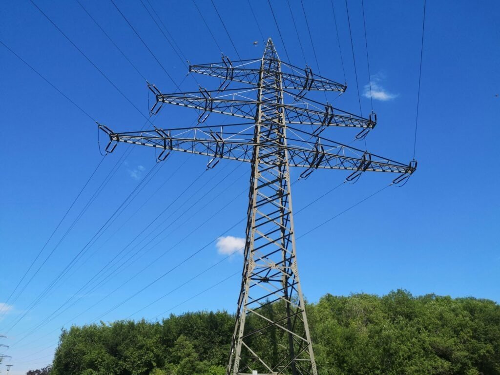
Proper transformer sizing is essential for ensuring efficient, reliable, and safe operation in electrical systems. A transformer that is too small may overheat and fail under load, while an oversized transformer can increase installation costs and reduce efficiency. Transformer sizing therefore involves carefully evaluating electrical demand, load characteristics, operating conditions, and future expansion requirements.
What Factors Determine Transformer Size Requirements?
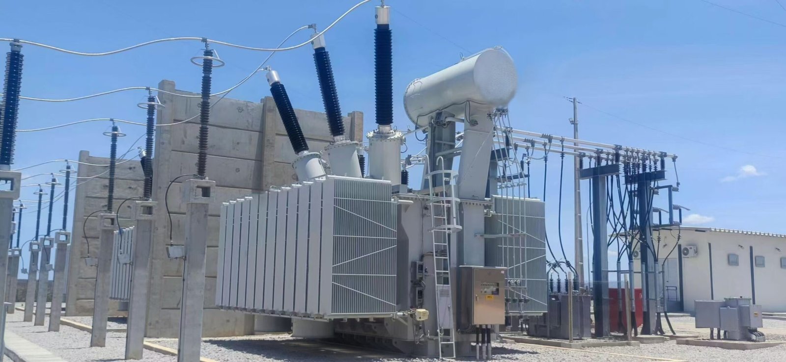
Selecting the correct transformer size is one of the most important decisions in electrical system design because transformer capacity directly affects power reliability, energy efficiency, operational safety, future expansion capability, and equipment lifespan. An undersized transformer may overheat, suffer insulation degradation, experience voltage instability, and fail prematurely, while an oversized transformer may create unnecessary capital cost, increased no-load losses, poor efficiency at low loading conditions, and wasted infrastructure investment.
Transformer size requirements are determined by a combination of electrical load demand, voltage levels, system configuration, load characteristics, environmental conditions, cooling methods, efficiency requirements, fault tolerance, harmonic content, future growth expectations, and application-specific operating conditions. Different industries, utilities, renewable energy systems, commercial buildings, and industrial plants each require transformer sizing strategies tailored to their unique electrical profiles.
Modern transformer sizing has become even more complex due to renewable energy integration, electric vehicle charging systems, data center growth, harmonic-producing electronic loads, smart grid technologies, and distributed generation systems. Engineers must carefully evaluate both present and future operating conditions to ensure transformers operate safely and efficiently throughout their expected service life.
Transformer size requirements are determined by electrical load demand, voltage levels, load characteristics, environmental conditions, cooling systems, efficiency goals, harmonic content, future expansion needs, and application-specific operating requirements.
Proper transformer sizing ensures reliable power delivery, minimizes losses, improves safety, supports future growth, and extends equipment lifespan.
Transformer size only depends on the total connected electrical load, so environmental conditions and load characteristics do not significantly affect sizing requirements.False
Transformer sizing depends on many factors including load type, harmonics, cooling conditions, ambient temperature, duty cycle, future expansion, and operating environment, not just connected load.
Why Transformer Sizing Is Important
Transformer sizing directly affects electrical system performance and reliability.
Main Objectives of Proper Transformer Sizing
| Objective | Importance |
|---|---|
| Reliable power delivery | Prevent outages |
| Thermal stability | Avoid overheating |
| Energy efficiency | Reduce losses |
| Equipment protection | Extend lifespan |
| Future scalability | Support expansion |
Improper sizing can create major operational and financial problems.
Electrical Load Demand
Load demand is the most fundamental transformer sizing factor.
What Is Load Demand?
Electrical load demand refers to the total power required by connected equipment.
Basic Power Equation
P=VI
Where:
- (P) = power
- (V) = voltage
- (I) = current
Transformer size must safely support required load power.
Apparent Power and Transformer Rating
Transformers are usually rated in kVA or MVA.
Apparent Power Equation
S=VI
Where:
- (S) = apparent power
- (V) = voltage
- (I) = current
Why Transformers Use kVA Ratings
Transformer heating depends on voltage and current regardless of load power factor.
Power Relationships
P = S × cos φ
Where:
- (P) = real power
- (S) = apparent power
- (cos φ) = power factor
Types of Electrical Loads
Different load types affect transformer sizing differently.
Common Load Types
| Load Type | Transformer Impact |
|---|---|
| Resistive loads | Stable operation |
| Inductive motor loads | High starting current |
| Electronic loads | Harmonics generation |
| Nonlinear loads | Additional heating |
Motor Starting Current Requirements
Motor loads often require larger transformer sizing margins.
Typical Motor Starting Characteristics
| Motor Type | Starting Current |
|---|---|
| Standard induction motor | 5–7× rated current |
| Large industrial motor | 6–10× rated current |
Transformers must handle temporary inrush current safely.
Continuous vs Intermittent Loading
Load duty cycle strongly affects transformer sizing.
Load Duty Types
| Duty Type | Sizing Requirement |
|---|---|
| Continuous load | Full thermal rating needed |
| Intermittent load | Reduced thermal stress |
| Cyclic load | Variable loading consideration |
Voltage Levels and System Configuration
Voltage affects current requirements and transformer design.
Relationship Between Voltage and Current
I = P/V
Higher voltage reduces current for the same power level.
Single-Phase vs Three-Phase Systems
Three-phase systems use different transformer sizing methods.
Three-Phase Power Equation
P = √3 VI cos φ
Comparison of System Types
| System Type | Typical Application |
|---|---|
| Single-phase | Residential loads |
| Three-phase | Industrial and utility systems |
Harmonic Content and Nonlinear Loads
Modern electronic equipment creates harmonics.
Common Harmonic Sources
| Source | Application |
|---|---|
| Variable-frequency drives | Industrial automation |
| Solar inverters | Renewable energy |
| Data centers | IT infrastructure |
| EV chargers | Transportation systems |
Harmonic Heating Effects
Harmonics increase transformer losses and temperature.
Harmonic Distortion Equation
THD=\frac{\sqrt{V_2^2+V_3^2+\cdots}}{V_1}\times100%
Higher harmonic levels often require larger transformer capacity.
Ambient Temperature and Environmental Conditions
Environmental conditions strongly influence transformer sizing.
Environmental Factors
| Condition | Transformer Impact |
|---|---|
| High ambient temperature | Reduced cooling capability |
| High altitude | Reduced heat dissipation |
| Humidity | Insulation stress |
| Dust contamination | Cooling reduction |
Temperature Rise and Thermal Limits
Transformer temperature directly affects insulation lifespan.
Thermal Aging Principle
Higher operating temperature accelerates insulation degradation.
Cooling Method Selection
Cooling capability affects allowable transformer size.
Common Cooling Methods
| Cooling Method | Application |
|---|---|
| ONAN | Standard distribution transformers |
| ONAF | Large utility transformers |
| OFAF | High-capacity industrial systems |
Better cooling allows higher loading capacity.
Efficiency Requirements
Efficiency goals affect transformer selection and sizing.
Transformer Efficiency Equation
\eta=\frac{P{out}}{P{in}}\times100%
Higher-efficiency transformers may require larger core designs.
Future Expansion Requirements
Many systems require future load growth consideration.
Why Expansion Margin Matters
| Reason | Benefit |
|---|---|
| Facility growth | Avoid transformer replacement |
| Additional equipment | Capacity reserve |
| Renewable integration | Future flexibility |
Typical Design Margin Practices
Engineers often include spare capacity.
Common Sizing Margins
| Application | Typical Margin |
|---|---|
| Commercial buildings | 20–30% |
| Industrial plants | 25–40% |
| Utility substations | Long-term planning margin |
Fault Current and Short-Circuit Requirements
Transformers must survive fault conditions safely.
Short-Circuit Current Equation
I{sc}=\frac{I{rated}}{Z_{pu}}
Why Fault Tolerance Matters
| Requirement | Importance |
|---|---|
| Mechanical strength | Prevent winding damage |
| Thermal withstand | Avoid insulation failure |
| Protection coordination | Safe fault clearing |
Renewable Energy Integration Requirements
Renewable systems introduce additional sizing complexity.
Renewable Energy Challenges
| Challenge | Transformer Requirement |
|---|---|
| Variable output | Dynamic loading capability |
| Harmonics | Thermal derating |
| Bidirectional flow | Reverse power capability |
Data Centers and High-Density Loads
Modern data centers require specialized transformer sizing.
Data Center Considerations
| Factor | Impact |
|---|---|
| Continuous high loading | Thermal stress |
| Harmonics | Additional heating |
| Reliability requirements | Redundancy planning |
Transformer Impedance and Load Sharing
Impedance affects system stability and parallel operation.
Importance of Impedance
| Function | Impact |
|---|---|
| Fault current limitation | System protection |
| Parallel load sharing | Balanced operation |
| Voltage regulation | Stable power delivery |
Space and Installation Constraints
Physical installation limitations also influence transformer design.
Installation Considerations
| Factor | Impact |
|---|---|
| Indoor installation | Dry-type transformer preference |
| Limited space | Compact design |
| Noise restrictions | Low-noise construction |
Regulatory Standards and Codes
Transformer sizing must comply with standards.
Common Standards
| Standard | Organization |
|---|---|
| IEC 60076 | IEC |
| IEEE C57 | IEEE |
| NEC | National Electrical Code |
Typical Transformer Sizes by Application
| Application | Common Transformer Size |
|---|---|
| Residential | 10–100 kVA |
| Commercial buildings | 100–2500 kVA |
| Industrial facilities | 1–100 MVA |
| Utility substations | 10–1000 MVA |
Smart Transformers and Adaptive Sizing
Modern smart transformers optimize loading dynamically.
Smart Features
| Technology | Benefit |
|---|---|
| Real-time monitoring | Improved utilization |
| Predictive analytics | Reduced overload risk |
| Dynamic thermal modeling | Better capacity management |
Future Trends in Transformer Sizing
Transformer sizing strategies continue evolving.
Emerging Trends
| Trend | Future Impact |
|---|---|
| Renewable integration | Variable load management |
| AI-assisted sizing | Improved optimization |
| Solid-state transformers | Compact high-capacity systems |
| Smart grid operation | Dynamic loading capability |
Key Factors Determining Transformer Size Requirements
| Factor | Influence on Size |
|---|---|
| Electrical load demand | Base capacity requirement |
| Motor starting current | Temporary overload capability |
| Harmonics | Additional thermal capacity |
| Ambient temperature | Cooling performance |
| Future expansion | Spare capacity margin |
| Voltage level | Current reduction |
| Cooling method | Thermal capability |
| Fault tolerance | Mechanical strength |
How Is Load Demand Calculated for Transformer Sizing?
Load demand calculation is one of the most critical steps in transformer sizing because it determines how much electrical power the transformer must safely and efficiently deliver under normal and peak operating conditions. Accurate load demand calculation ensures reliable system performance, prevents transformer overloading, improves energy efficiency, supports future expansion, and minimizes unnecessary equipment cost. If load demand is underestimated, transformers may overheat, experience insulation damage, suffer voltage instability, and fail prematurely. If it is greatly overestimated, the transformer may operate inefficiently with excessive no-load losses and unnecessary capital expense.
Transformer load demand is calculated by evaluating the total connected electrical loads, applying demand factors, considering load diversity, accounting for power factor, analyzing duty cycles, and determining maximum expected simultaneous power consumption. Different applications such as residential buildings, commercial facilities, industrial plants, renewable energy systems, hospitals, and data centers each require different load calculation methods because their operating characteristics vary significantly.
Modern electrical systems also include nonlinear loads such as variable-frequency drives, solar inverters, battery storage systems, electric vehicle chargers, and data centers that introduce harmonics and fluctuating power demand, making transformer load analysis more complex than traditional steady-state calculations.
Load demand for transformer sizing is calculated by determining the total connected load, applying demand and diversity factors, evaluating peak simultaneous power usage, accounting for power factor and harmonics, and converting the resulting electrical demand into transformer kVA capacity requirements.
Accurate load demand calculation is essential for selecting a transformer that operates safely, efficiently, and reliably under both present and future conditions.
Transformer load demand is simply equal to the sum of all connected equipment ratings because all electrical devices operate at full load simultaneously.False
Electrical systems rarely operate with all connected equipment at full load simultaneously. Demand factors, diversity factors, load cycles, and power factor must be considered when calculating transformer load demand.
Why Load Demand Calculation Is Important
Transformer sizing depends directly on expected electrical demand.
Main Objectives of Load Calculation
| Objective | Importance |
|---|---|
| Prevent transformer overload | Improve reliability |
| Ensure voltage stability | Maintain power quality |
| Optimize transformer efficiency | Reduce losses |
| Support future expansion | Avoid replacement costs |
Improper calculations can create serious operational problems.
Understanding Electrical Load
Electrical load refers to the power consumed by connected equipment.
Common Electrical Loads
| Load Type | Examples |
|---|---|
| Resistive loads | Heaters, lighting |
| Inductive loads | Motors, pumps |
| Capacitive loads | Power factor correction |
| Nonlinear loads | Computers, VFDs, inverters |
Different load types affect transformer demand differently.
Basic Power Calculation
Electrical power is calculated using voltage and current.
Single-Phase Power Equation
P=VI\cos\phi
Where:
- (P) = real power
- (V) = voltage
- (I) = current
- (\cos\phi) = power factor
Three-Phase Power Calculation
Most industrial transformers use three-phase systems.
Three-Phase Power Equation
P=\sqrt{3}VI\cos\phi
Three-phase calculations are essential for industrial transformer sizing.
Apparent Power and Transformer Rating
Transformers are rated in apparent power rather than real power.
Apparent Power Equation
S=VI
Where:
- (S) = apparent power
Relationship Between kW and kVA
kVA=\frac{kW}{PF}
Where:
- PF = power factor
Low power factor increases transformer capacity requirements.
Connected Load Calculation
The first step is determining total connected equipment load.
Example Connected Loads
| Equipment | Rated Power |
|---|---|
| Motors | 500 kW |
| Lighting | 100 kW |
| HVAC systems | 300 kW |
| Office equipment | 50 kW |
Total Connected Load Formula
P_{total}=P_1+P_2+P_3+\cdots
However, connected load alone is not enough for transformer sizing.
Demand Factor
Not all equipment operates at full load simultaneously.
Demand Factor Equation
Demand\ Factor=\frac{Maximum\ Demand}{Total\ Connected\ Load}
Why Demand Factors Matter
Using connected load only often oversizes transformers unnecessarily.
Typical Demand Factors
| Application | Typical Demand Factor |
|---|---|
| Residential buildings | 0.4–0.7 |
| Commercial buildings | 0.6–0.8 |
| Industrial plants | 0.7–0.9 |
Diversity Factor
Different loads operate at different times.
Diversity Factor Equation
Diversity\ Factor=\frac{Sum\ of\ Individual\ Maximum\ Demands}{Maximum\ System\ Demand}
Importance of Diversity
Diversity reduces total simultaneous demand.
Benefits of Diversity Consideration
| Benefit | Result |
|---|---|
| Smaller transformer size | Lower capital cost |
| Improved efficiency | Better utilization |
| Reduced oversizing | Lower losses |
Maximum Demand Calculation
Transformer sizing focuses on maximum expected demand.
Maximum Demand Considerations
| Factor | Importance |
|---|---|
| Peak operating hours | Highest load period |
| Seasonal variation | Cooling/heating demand |
| Production cycles | Industrial loading |
| Expansion planning | Future capacity |
Continuous vs Intermittent Loads
Load duration strongly affects transformer requirements.
Load Duty Types
| Load Type | Transformer Impact |
|---|---|
| Continuous load | Full thermal loading |
| Intermittent load | Reduced heating effect |
| Cyclic load | Variable thermal stress |
Motor Load Calculations
Motors significantly affect transformer sizing.
Motor Starting Current
| Motor Type | Typical Starting Current |
|---|---|
| Standard induction motor | 5–7× rated current |
| Large industrial motor | 6–10× rated current |
Why Motor Starting Matters
Transformer voltage drop during motor starting must remain acceptable.
Voltage Drop Equation
V_{drop}=IZ
Where:
- (I) = current
- (Z) = impedance
Power Factor Correction
Poor power factor increases transformer loading.
Power Factor Impact
| Power Factor | Transformer Effect |
|---|---|
| High PF | Lower current |
| Low PF | Higher current |
| Poor PF | Larger transformer needed |
Harmonic Loads and Nonlinear Equipment
Modern electronic equipment creates harmonics.
Common Harmonic Sources
| Source | Application |
|---|---|
| Variable-frequency drives | Industrial systems |
| Solar inverters | Renewable energy |
| EV chargers | Transportation systems |
| Data centers | IT infrastructure |
Harmonic Heating Effects
Harmonics increase transformer losses and temperature.
Harmonic Distortion Equation
THD=\frac{\sqrt{V_2^2+V_3^2+\cdots}}{V_1}\times100%
High harmonic levels may require transformer derating.
Environmental Conditions
Ambient conditions affect transformer capacity.
Environmental Factors
| Condition | Impact |
|---|---|
| High temperature | Reduced cooling |
| High altitude | Lower heat dissipation |
| Humidity | Insulation stress |
Future Expansion Margin
Most systems require future growth allowance.
Typical Expansion Margins
| Application | Common Margin |
|---|---|
| Commercial buildings | 20–30% |
| Industrial facilities | 25–40% |
| Data centers | High scalability margin |
Sample Transformer Load Demand Calculation
Example Data
| Parameter | Value |
|---|---|
| Connected load | 1000 kW |
| Demand factor | 0.8 |
| Power factor | 0.9 |
Step 1: Maximum Demand
Maximum\ Demand=1000\times0.8=800\ kW
Step 2: Convert to kVA
kVA=\frac{800}{0.9}=889\ kVA
Step 3: Add Expansion Margin
If a 25% margin is required:
Final\ Size=889\times1.25=1111\ kVA
The engineer would likely select a standard 1250 kVA transformer.
Industrial Transformer Load Considerations
Industrial facilities require detailed load analysis.
Industrial Load Factors
| Factor | Importance |
|---|---|
| Motor starting | Voltage stability |
| Harmonics | Thermal stress |
| Process cycles | Variable demand |
| Redundancy | Reliability |
Renewable Energy Transformer Demand
Renewable systems introduce fluctuating loading conditions.
Renewable Challenges
| Challenge | Transformer Requirement |
|---|---|
| Variable generation | Dynamic loading capability |
| Inverter harmonics | Harmonic tolerance |
| Bidirectional flow | Reverse power handling |
Data Centers and Critical Facilities
Critical infrastructure requires highly accurate sizing.
Critical Facility Requirements
| Requirement | Importance |
|---|---|
| Redundancy | Continuous operation |
| Harmonic tolerance | Stable power quality |
| High reliability | Reduced downtime |
Standards and Codes for Load Calculations
Transformer sizing follows international standards.
Common Standards
| Standard | Organization |
|---|---|
| NEC | National Electrical Code |
| IEC 60076 | IEC |
| IEEE C57 | IEEE |
Smart Monitoring and Dynamic Load Analysis
Modern systems increasingly use digital monitoring.
Smart Monitoring Benefits
| Technology | Benefit |
|---|---|
| Real-time load monitoring | Accurate utilization analysis |
| AI forecasting | Predictive demand planning |
| Smart meters | Dynamic load tracking |
Common Mistakes in Transformer Load Calculations
| Mistake | Consequence |
|---|---|
| Ignoring demand factor | Oversized transformer |
| Ignoring harmonics | Transformer overheating |
| No future expansion margin | Early replacement |
| Incorrect power factor assumptions | Improper sizing |
Key Factors in Transformer Load Demand Calculation
| Factor | Influence |
|---|---|
| Connected load | Base demand |
| Demand factor | Simultaneous usage |
| Diversity factor | System utilization |
| Power factor | Current requirement |
| Harmonics | Thermal derating |
| Environmental conditions | Cooling capability |
| Future expansion | Spare capacity |
Why Are Voltage Level and Power Rating Important?
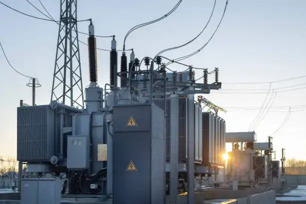
Voltage level and power rating are two of the most critical parameters in transformer design, selection, and operation because they determine how efficiently, safely, and reliably electrical energy can be transmitted, distributed, and utilized throughout power systems. Proper voltage selection ensures efficient energy transfer with minimal losses, while correct power rating guarantees that the transformer can safely handle expected electrical demand without overheating, voltage instability, insulation degradation, or premature failure.
Transformers exist primarily to convert voltage from one level to another. Electrical power generated by power plants, renewable energy facilities, and industrial generators cannot be transmitted efficiently at low voltage because low-voltage transmission produces excessively high current, severe conductor heating, large voltage drops, and significant energy loss. By increasing voltage through transformers, electrical systems reduce current flow and dramatically improve transmission efficiency.
Power rating is equally important because it defines the amount of electrical load a transformer can safely carry under specified operating conditions. Transformers that are undersized may overheat and fail, while oversized transformers may operate inefficiently and increase unnecessary capital cost. Engineers must therefore carefully match transformer voltage levels and power ratings to application requirements, environmental conditions, load characteristics, and future expansion plans.
Modern electrical systems including renewable energy grids, smart substations, electric vehicle charging infrastructure, industrial automation, and data centers all depend heavily on optimized transformer voltage and power rating selection to maintain system stability, energy efficiency, and operational reliability.
Voltage level is important because it determines transmission efficiency, current flow, insulation requirements, and system compatibility, while power rating is important because it defines the transformer’s load-carrying capacity, thermal performance, reliability, and operational safety.
Improper voltage or power rating selection can lead to excessive losses, overheating, unstable operation, equipment damage, and reduced transformer lifespan.
Transformer voltage level and power rating only affect electrical capacity and have little influence on efficiency or system reliability.False
Voltage level and power rating directly affect transmission efficiency, current flow, thermal performance, system stability, insulation stress, energy loss, and overall reliability of electrical power systems.
Why Voltage Level Matters in Power Systems
Voltage level strongly affects how efficiently electrical energy is transmitted.
Basic Electrical Power Equation
P=VI
Where:
- (P) = power
- (V) = voltage
- (I) = current
For constant power, increasing voltage reduces current.
Why Reducing Current Is Important
High current creates several electrical problems.
Problems Caused by High Current
| Problem | Consequence |
|---|---|
| Conductor heating | Energy waste |
| Voltage drop | Poor power quality |
| Cable overheating | Reduced lifespan |
| Larger conductor size | Higher infrastructure cost |
Transmission Loss Reduction
Electrical transmission losses increase with current.
Power Loss Equation
P_{loss}=I^2R
Where:
- (P_{loss}) = transmission loss
- (I) = current
- (R) = conductor resistance
Lower current dramatically reduces energy loss.
How Transformers Enable Efficient Transmission
Transformers increase voltage for long-distance transmission.
Transformer Voltage Relationship
\frac{V_p}{V_s}=\frac{N_p}{N_s}
Where:
- (V_p) = primary voltage
- (V_s) = secondary voltage
- (N_p) = primary winding turns
- (N_s) = secondary winding turns
Higher secondary turns produce higher voltage.
Typical Voltage Levels in Power Systems
Different parts of the electrical grid use different voltage levels.
Common Voltage Ranges
| Application | Typical Voltage |
|---|---|
| Residential distribution | 120V–415V |
| Commercial distribution | 11kV–33kV |
| Transmission systems | 66kV–765kV |
| Renewable energy collection | 33kV–220kV |
Voltage Level and Insulation Requirements
Higher voltage requires stronger insulation systems.
Insulation Challenges
| Voltage Increase | Impact |
|---|---|
| Higher electric stress | Increased insulation thickness |
| Greater clearance distance | Larger transformer size |
| Stronger dielectric design | Higher manufacturing complexity |
Voltage Regulation Importance
Stable voltage is essential for reliable power delivery.
Voltage Regulation Equation
VR%=\frac{V{NL}-V{FL}}{V_{FL}}\times100
Where:
- (VR%) = voltage regulation
- (V_{NL}) = no-load voltage
- (V_{FL}) = full-load voltage
Good voltage regulation improves power quality.
Why Power Rating Matters
Power rating defines transformer load capacity.
Apparent Power Equation
S=VI
Where:
- (S) = apparent power
Transformers are usually rated in kVA or MVA.
Why Transformers Use kVA Ratings
Transformer heating depends on voltage and current rather than power factor.
Relationship Between kW and kVA
P=S\cos\phi
Where:
- (P) = real power
- (S) = apparent power
- (\cos\phi) = power factor
Thermal Limits and Power Rating
Transformer loading directly affects temperature rise.
Main Heat Sources
| Heat Source | Description |
|---|---|
| Copper losses | Current-related heating |
| Core losses | Magnetic losses |
| Harmonic losses | Nonlinear load heating |
Why Overloading Is Dangerous
Excessive loading accelerates transformer aging.
Overloading Risks
| Risk | Consequence |
|---|---|
| Insulation degradation | Reduced lifespan |
| Oil overheating | Cooling failure |
| Winding deformation | Mechanical damage |
| Thermal runaway | Catastrophic failure |
Transformer Efficiency and Power Rating
Transformer efficiency changes with loading conditions.
Efficiency Equation
\eta=\frac{P{out}}{P{in}}\times100%
Why Correct Sizing Improves Efficiency
| Condition | Efficiency Effect |
|---|---|
| Undersized transformer | Overheating losses |
| Oversized transformer | Excess no-load losses |
| Properly sized transformer | Optimal efficiency |
Power Rating and Cooling Systems
Larger transformers require more advanced cooling.
Common Cooling Methods
| Cooling Method | Application |
|---|---|
| ONAN | Small and medium transformers |
| ONAF | Large utility transformers |
| OFAF | High-capacity transmission transformers |
Load Characteristics and Power Rating
Different loads affect transformer sizing differently.
Load Types
| Load Type | Transformer Impact |
|---|---|
| Resistive loads | Stable loading |
| Motor loads | High starting current |
| Harmonic loads | Additional heating |
| Cyclic loads | Variable thermal stress |
Motor Starting and Temporary Overloads
Motors create large temporary currents.
Typical Starting Currents
| Motor Type | Starting Current |
|---|---|
| Standard induction motor | 5–7× rated current |
| Large industrial motor | 6–10× rated current |
Transformers must withstand these temporary loads.
Renewable Energy Applications
Renewable systems require careful voltage and power selection.
Renewable Energy Challenges
| Challenge | Transformer Requirement |
|---|---|
| Variable generation | Dynamic loading capability |
| Inverter harmonics | Thermal derating |
| Long-distance transmission | High-voltage operation |
Data Centers and Critical Infrastructure
Modern digital infrastructure requires highly reliable transformers.
Critical System Requirements
| Requirement | Importance |
|---|---|
| Stable voltage | Equipment protection |
| High reliability | Continuous operation |
| Harmonic tolerance | Power quality |
Short-Circuit Strength and Power Rating
Larger transformers must survive higher fault forces.
Short-Circuit Current Equation
I{sc}=\frac{I{rated}}{Z_{pu}}
Why Short-Circuit Capability Matters
| Requirement | Importance |
|---|---|
| Mechanical strength | Prevent winding damage |
| Thermal withstand | Protect insulation |
| Protection coordination | Safe fault clearing |
Environmental Conditions and Voltage Selection
Environmental factors influence transformer design.
Environmental Impacts
| Condition | Transformer Effect |
|---|---|
| High altitude | Reduced cooling |
| High humidity | Insulation stress |
| Extreme temperature | Thermal derating |
Harmonics and Power Rating
Nonlinear loads increase transformer heating.
Harmonic Sources
| Source | Application |
|---|---|
| Variable-frequency drives | Industrial automation |
| Solar inverters | Renewable energy |
| EV chargers | Transportation systems |
Smart Transformers and Adaptive Operation
Modern transformers increasingly use digital technologies.
Smart Transformer Features
| Feature | Benefit |
|---|---|
| Real-time monitoring | Improved reliability |
| Dynamic load management | Better utilization |
| Predictive maintenance | Reduced downtime |
Economic Importance of Voltage and Power Rating
Proper transformer selection improves project economics.
Financial Benefits
| Benefit | Result |
|---|---|
| Reduced losses | Lower operating cost |
| Correct sizing | Lower capital waste |
| Improved lifespan | Reduced replacement cost |
International Standards for Voltage and Power Ratings
Transformer ratings follow global standards.
Common Standards
| Standard | Organization |
|---|---|
| IEC 60076 | IEC |
| IEEE C57 | IEEE |
| ANSI standards | ANSI |
Typical Transformer Ratings by Application
| Application | Typical Rating |
|---|---|
| Residential distribution | 10–100 kVA |
| Commercial facilities | 100–2500 kVA |
| Industrial systems | 1–100 MVA |
| Transmission substations | 100–1000 MVA |
Future Trends in Voltage and Power Optimization
Transformer systems continue evolving rapidly.
Emerging Technologies
| Technology | Future Impact |
|---|---|
| Smart grids | Dynamic voltage control |
| Solid-state transformers | Compact high-capacity operation |
| Renewable integration | Adaptive voltage management |
| AI optimization | Intelligent loading control |
Key Reasons Voltage Level and Power Rating Are Important
| Parameter | Importance |
|---|---|
| Voltage level | Efficient transmission |
| Power rating | Safe load handling |
| Voltage stability | Reliable operation |
| Thermal performance | Long equipment lifespan |
| Proper sizing | Improved efficiency |
| Harmonic tolerance | Better power quality |
How Do Load Type and Duty Cycle Affect Transformer Selection?

Load type and duty cycle are two of the most important factors influencing transformer selection because they directly affect transformer heating, efficiency, voltage regulation, overload capability, insulation lifespan, cooling requirements, harmonic performance, and long-term operational reliability. Transformers are not selected based solely on total power demand; they must also be matched to the specific electrical behavior and operating patterns of the connected load. Different loads produce different current characteristics, power factor conditions, starting surges, harmonics, and thermal stress levels that significantly impact transformer performance.
A transformer supplying steady resistive heating loads behaves very differently from a transformer powering large motors, renewable energy inverters, data centers, welding equipment, or electric vehicle charging systems. Some loads create severe inrush currents, some generate harmonic distortion, and others fluctuate rapidly throughout the day. Likewise, duty cycle determines how long and how frequently the transformer operates under load, which strongly affects thermal aging and allowable loading capacity.
Modern electrical systems are increasingly dominated by nonlinear electronic loads, renewable energy systems, industrial automation, battery storage systems, and high-density computing infrastructure. These applications require more advanced transformer selection strategies than traditional steady-state electrical systems because they introduce variable loading patterns, harmonics, rapid load changes, and thermal cycling.
Load type affects transformer selection by influencing current characteristics, harmonics, starting surges, voltage regulation, and thermal stress, while duty cycle affects transformer sizing, cooling requirements, insulation aging, overload capability, and allowable operating temperature.
Proper consideration of load type and duty cycle ensures reliable transformer operation, higher efficiency, longer lifespan, and improved power quality.
Transformer selection only depends on total load capacity, so load type and operating duty cycle have little effect on transformer performance.False
Different load types and duty cycles strongly affect transformer heating, harmonics, voltage regulation, cooling requirements, insulation aging, and overload capability, making them critical selection factors.
Why Load Characteristics Matter in Transformer Selection
Electrical loads do not behave identically.
Main Electrical Load Characteristics
| Characteristic | Transformer Impact |
|---|---|
| Current waveform | Heating and harmonics |
| Starting current | Voltage drop |
| Power factor | Apparent power requirement |
| Load fluctuation | Thermal cycling |
Transformers must be selected according to these conditions.
What Is Load Type?
Load type refers to the electrical behavior of connected equipment.
Common Load Categories
| Load Type | Examples |
|---|---|
| Resistive loads | Heaters, incandescent lighting |
| Inductive loads | Motors, pumps, compressors |
| Capacitive loads | Capacitor banks |
| Nonlinear loads | Computers, VFDs, solar inverters |
Each category affects transformers differently.
Resistive Loads and Transformer Selection
Resistive loads are the simplest transformer applications.
Characteristics of Resistive Loads
| Characteristic | Effect |
|---|---|
| Stable current | Predictable loading |
| Near-unity power factor | Lower apparent power |
| Minimal harmonics | Reduced heating |
These loads place relatively low stress on transformers.
Inductive Loads and Motor Applications
Motor loads create significant transformer stress.
Motor Load Characteristics
| Characteristic | Transformer Effect |
|---|---|
| High starting current | Temporary overload |
| Reactive power demand | Lower power factor |
| Variable load cycles | Thermal fluctuation |
Motor Starting Current
Motor startup creates very large temporary currents.
Typical Starting Current Levels
| Motor Type | Starting Current |
|---|---|
| Small induction motor | 4–6× rated current |
| Large industrial motor | 6–10× rated current |
Why Starting Current Matters
High starting current causes voltage drop and thermal stress.
Voltage Drop Equation
V_{drop}=IZ
Where:
- (I) = current
- (Z) = impedance
Transformers must withstand temporary motor surges safely.
Nonlinear Loads and Harmonics
Modern electronic equipment generates harmonics.
Common Nonlinear Loads
| Load | Application |
|---|---|
| Variable-frequency drives | Industrial automation |
| Solar inverters | Renewable energy |
| Data centers | Information technology |
| EV chargers | Transportation systems |
Harmonic Distortion Effects
Harmonics increase transformer losses and temperature.
Harmonic Distortion Equation
THD=\frac{\sqrt{V_2^2+V_3^2+\cdots}}{V_1}\times100%
Where:
- THD = total harmonic distortion
- (V_1) = fundamental voltage
Why Harmonics Affect Transformer Selection
| Harmonic Effect | Consequence |
|---|---|
| Additional heating | Reduced lifespan |
| Eddy current losses | Lower efficiency |
| Insulation stress | Premature aging |
Transformers supplying nonlinear loads may require derating or K-rated designs.
K-Rated Transformers
K-rated transformers are designed for harmonic-rich environments.
Features of K-Rated Transformers
| Feature | Benefit |
|---|---|
| Reinforced winding design | Harmonic heating tolerance |
| Enhanced cooling | Lower temperature rise |
| Reduced eddy losses | Improved durability |
Capacitive Loads and Voltage Stability
Capacitive loads affect system voltage differently.
Capacitive Load Characteristics
| Characteristic | Effect |
|---|---|
| Leading power factor | Voltage rise |
| Reactive power injection | Grid stabilization |
Duty Cycle and Transformer Selection
Duty cycle refers to how long and how frequently a load operates.
Main Duty Cycle Categories
| Duty Type | Description |
|---|---|
| Continuous duty | Constant operation |
| Intermittent duty | Periodic operation |
| Cyclic duty | Repeating load changes |
| Short-time duty | Temporary loading |
Continuous Duty Transformers
Continuous-duty transformers operate under steady load.
Characteristics
| Feature | Requirement |
|---|---|
| Constant thermal loading | Full cooling capability |
| Stable operation | Long-term reliability |
Intermittent Duty Operation
Intermittent loads allow cooling periods between operation cycles.
Benefits of Intermittent Loading
| Benefit | Effect |
|---|---|
| Lower average temperature | Reduced insulation aging |
| Temporary overload capability | Smaller transformer possible |
Cyclic Duty and Thermal Cycling
Cyclic loads repeatedly heat and cool transformers.
Cyclic Load Applications
| Application | Example |
|---|---|
| Industrial production | Batch processing |
| Railway systems | Train acceleration cycles |
| Renewable systems | Solar generation variability |
Thermal Aging and Duty Cycle
Transformer lifespan strongly depends on operating temperature.
Thermal Aging Principle
Higher temperature accelerates insulation deterioration.
Transformer Efficiency and Loading
Efficiency changes with load level.
Efficiency Equation
\eta=\frac{P{out}}{P{in}}\times100%
Why Load Profile Matters for Efficiency
| Loading Condition | Efficiency Impact |
|---|---|
| Very light load | Higher no-load loss percentage |
| Overload | Excessive copper losses |
| Proper loading | Optimal efficiency |
Load Factor and Transformer Utilization
Load factor measures average loading.
Load Factor Equation
Load\ Factor=\frac{Average\ Load}{Peak\ Load}
Importance of Load Factor
| High Load Factor | Low Load Factor |
|---|---|
| Better utilization | Lower utilization |
| Stable thermal condition | Variable thermal stress |
Renewable Energy Duty Cycles
Renewable energy systems create highly variable loading.
Renewable Load Characteristics
| Renewable Source | Duty Cycle Behavior |
|---|---|
| Solar farms | Daytime generation cycle |
| Wind farms | Variable wind-dependent loading |
| Battery systems | Bidirectional charging cycles |
Data Centers and Continuous Critical Loads
Data centers require extremely reliable transformers.
Data Center Characteristics
| Characteristic | Transformer Impact |
|---|---|
| Continuous operation | Constant thermal loading |
| Harmonic-rich loads | Additional heating |
| High reliability demand | Redundant transformer systems |
Welding Loads and Extreme Duty Cycles
Welding equipment creates severe intermittent loading.
Welding Transformer Challenges
| Challenge | Effect |
|---|---|
| Rapid load fluctuation | Thermal cycling |
| High short-duration current | Mechanical stress |
Cooling Method and Duty Cycle
Cooling capability affects allowable duty cycle.
Common Cooling Methods
| Cooling Method | Application |
|---|---|
| ONAN | Standard continuous duty |
| ONAF | Variable heavy loading |
| OFAF | High-capacity cyclic loads |
Short-Time Overload Capability
Some transformers tolerate temporary overloads.
Overload Considerations
| Factor | Importance |
|---|---|
| Duration | Thermal accumulation |
| Ambient temperature | Cooling effectiveness |
| Previous load history | Existing thermal condition |
Smart Monitoring for Variable Loads
Modern transformers use digital monitoring systems.
Smart Monitoring Functions
| Technology | Benefit |
|---|---|
| Real-time thermal monitoring | Improved overload management |
| Dynamic load analysis | Better utilization |
| Predictive maintenance | Reduced failure risk |
Industrial Applications and Load Diversity
Industrial plants often combine many load types.
Mixed Industrial Loads
| Load Type | Example |
|---|---|
| Motors | Pumps and compressors |
| Electronic systems | Automation controls |
| Heating systems | Process heaters |
Transformers must handle combined loading characteristics.
Standards for Transformer Selection
Transformer selection follows international standards.
Common Standards
| Standard | Organization |
|---|---|
| IEC 60076 | IEC |
| IEEE C57 | IEEE |
| NEMA standards | NEMA |
Common Transformer Selection Mistakes
| Mistake | Consequence |
|---|---|
| Ignoring harmonics | Overheating |
| Ignoring duty cycle | Reduced lifespan |
| Undersized cooling | Thermal stress |
| Incorrect motor sizing | Voltage instability |
Key Effects of Load Type and Duty Cycle on Transformer Selection
| Factor | Transformer Impact |
|---|---|
| Motor starting current | Temporary overload capability |
| Harmonics | Additional heating |
| Continuous duty | Thermal design |
| Cyclic loading | Insulation aging |
| Intermittent duty | Reduced average temperature |
| Nonlinear loads | K-rated transformer requirement |
How Are Environmental and Cooling Conditions Considered?
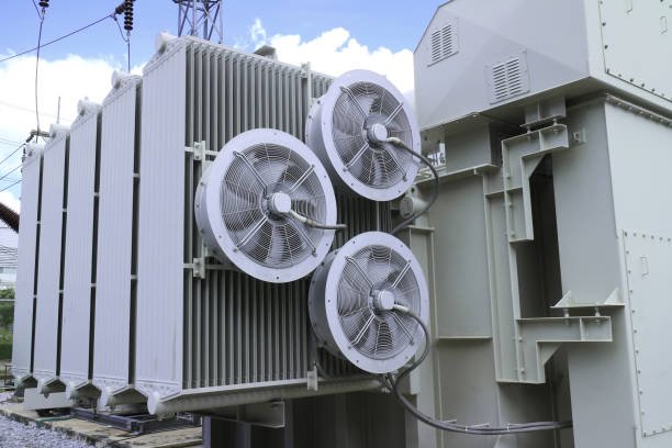
Environmental and cooling conditions are critical considerations in transformer design, selection, installation, and operation because they directly influence transformer temperature rise, insulation lifespan, cooling efficiency, load capacity, operational reliability, and long-term safety. Transformers continuously generate heat during operation due to copper losses, core losses, stray losses, and harmonic heating. If this heat is not properly dissipated under the surrounding environmental conditions, transformer insulation degrades rapidly, efficiency decreases, and the risk of overheating, oil breakdown, and catastrophic failure increases significantly.
Environmental conditions such as ambient temperature, altitude, humidity, dust contamination, corrosive atmosphere, seismic activity, solar radiation, rainfall, flooding risk, and salt exposure all affect transformer performance and cooling effectiveness. A transformer installed in a cool indoor environment behaves very differently from one operating in a desert solar farm, offshore wind installation, tropical coastal substation, underground metro system, or heavy industrial facility.
Cooling conditions are equally important because transformer loading capability depends heavily on how efficiently heat can be removed from the windings and core. Different transformer cooling methods such as ONAN, ONAF, OFAF, and dry-type air cooling are selected based on load demand, installation environment, and operating conditions. Modern transformers also increasingly use intelligent thermal monitoring, smart cooling control systems, and predictive diagnostics to optimize cooling performance and extend equipment life.
Environmental and cooling conditions are considered by evaluating ambient temperature, altitude, humidity, contamination, ventilation, installation location, thermal loading, and cooling system performance to ensure safe transformer operation, effective heat dissipation, insulation protection, and long-term reliability.
Improper consideration of environmental or cooling conditions can lead to overheating, insulation degradation, reduced efficiency, premature aging, and transformer failure.
Transformer cooling performance is determined only by its internal design, so environmental conditions have little effect on operating temperature or reliability.False
Environmental conditions such as ambient temperature, altitude, humidity, dust, contamination, and ventilation strongly affect transformer cooling performance, thermal stress, insulation aging, and reliability.
Why Environmental Conditions Matter for Transformers
Transformers operate continuously under varying environmental conditions.
Main Environmental Factors
| Environmental Factor | Transformer Impact |
|---|---|
| Ambient temperature | Cooling effectiveness |
| Altitude | Air density reduction |
| Humidity | Insulation stress |
| Dust and pollution | Cooling obstruction |
| Salt contamination | Corrosion risk |
These conditions directly affect transformer thermal behavior.
Why Cooling Is Critical in Transformers
Transformers generate heat during normal operation.
Main Heat Sources
| Heat Source | Description |
|---|---|
| Copper losses | Winding resistance heating |
| Core losses | Magnetic hysteresis and eddy currents |
| Harmonic losses | Additional nonlinear load heating |
| Stray losses | Leakage flux heating |
Excessive heat damages transformer insulation.
Transformer Efficiency and Heat Generation
No transformer operates at 100% efficiency.
Efficiency Equation
\eta=\frac{P{out}}{P{in}}\times100%
Energy losses become heat inside the transformer.
Temperature Rise and Insulation Aging
Transformer insulation lifespan depends heavily on temperature.
Thermal Aging Principle
Higher operating temperature accelerates insulation degradation exponentially.
Why Overheating Is Dangerous
| Overheating Effect | Consequence |
|---|---|
| Insulation breakdown | Reduced lifespan |
| Oil degradation | Lower dielectric strength |
| Winding deformation | Mechanical failure |
| Gas generation | Internal fault risk |
Ambient Temperature Considerations
Ambient temperature is one of the most important cooling factors.
Typical Ambient Conditions
| Environment | Typical Temperature |
|---|---|
| Indoor substations | 20–30°C |
| Desert solar farms | 45–55°C |
| Cold climates | Below 0°C |
How Ambient Temperature Affects Cooling
Higher ambient temperature reduces heat dissipation capability.
Thermal Relationship
Q=hA(T_s-T_a)
Where:
- (Q) = heat transfer
- (h) = heat transfer coefficient
- (A) = cooling surface area
- (T_s) = surface temperature
- (T_a) = ambient temperature
Smaller temperature difference reduces cooling effectiveness.
Transformer Derating in High Temperatures
Transformers may require derating in hot environments.
Typical Thermal Derating Effects
| Ambient Temperature Increase | Effect |
|---|---|
| Moderate increase | Reduced overload capability |
| Extreme heat | Lower allowable loading |
Altitude and Air Density Effects
High-altitude installations reduce cooling efficiency.
Why Altitude Matters
Air density decreases with altitude, reducing heat transfer.
High-Altitude Challenges
| Altitude Effect | Transformer Impact |
|---|---|
| Reduced convection cooling | Higher temperature rise |
| Lower dielectric strength | Increased insulation stress |
Humidity and Moisture Considerations
Humidity strongly affects insulation systems.
Moisture Risks
| Moisture Effect | Consequence |
|---|---|
| Reduced insulation resistance | Increased failure risk |
| Oil contamination | Lower dielectric strength |
| Condensation | Surface tracking |
Coastal and Offshore Environments
Salt contamination creates severe corrosion challenges.
Coastal Environment Risks
| Risk | Impact |
|---|---|
| Salt spray | Corrosion |
| High humidity | Insulation deterioration |
| Strong winds | Cooling variability |
Dust and Pollution Effects
Industrial pollution can reduce cooling effectiveness.
Pollution Challenges
| Contaminant | Transformer Effect |
|---|---|
| Dust accumulation | Reduced radiator efficiency |
| Chemical pollution | Corrosion |
| Conductive particles | Flashover risk |
Solar Radiation and Outdoor Installations
Direct sunlight increases transformer temperature.
Solar Heating Impact
Outdoor transformers absorb additional heat from solar radiation.
Rain, Flooding, and Water Protection
Outdoor transformers require environmental protection.
Water-Related Risks
| Condition | Potential Problem |
|---|---|
| Heavy rain | Moisture ingress |
| Flooding | Catastrophic insulation failure |
| Standing water | Corrosion damage |
Seismic and Mechanical Environmental Conditions
Earthquake-prone regions require reinforced transformer structures.
Seismic Protection Features
| Feature | Purpose |
|---|---|
| Reinforced mounting | Mechanical stability |
| Flexible bushings | Vibration tolerance |
Transformer Cooling Methods
Cooling systems are selected according to environmental and load conditions.
Common Cooling Types
| Cooling Method | Description |
|---|---|
| ONAN | Oil Natural Air Natural |
| ONAF | Oil Natural Air Forced |
| OFAF | Oil Forced Air Forced |
| OFWF | Oil Forced Water Forced |
ONAN Cooling Systems
ONAN is the most common cooling method.
ONAN Characteristics
| Feature | Benefit |
|---|---|
| Natural oil circulation | Simplicity |
| Natural air convection | Low maintenance |
| No moving parts | High reliability |
Forced-Air Cooling Systems
Larger transformers often require fans.
ONAF Advantages
| Benefit | Result |
|---|---|
| Increased cooling capacity | Higher loading capability |
| Better thermal control | Reduced temperature rise |
Oil-Forced Cooling Systems
Very large transformers use pumped oil systems.
OFAF Cooling Benefits
| Benefit | Importance |
|---|---|
| High heat removal capacity | Large transformer operation |
| Improved thermal uniformity | Reduced hot spots |
Dry-Type Transformer Cooling
Dry-type transformers use air cooling instead of oil.
Dry-Type Cooling Features
| Feature | Benefit |
|---|---|
| No oil fire risk | Improved safety |
| Indoor suitability | Urban installations |
| Lower environmental risk | Eco-friendly operation |
Smart Cooling Systems
Modern transformers increasingly use intelligent cooling control.
Smart Cooling Technologies
| Technology | Function |
|---|---|
| Temperature sensors | Real-time monitoring |
| Automated fan control | Energy optimization |
| AI thermal analysis | Predictive cooling management |
Thermal Monitoring Systems
Continuous thermal monitoring improves reliability.
Monitored Parameters
| Parameter | Purpose |
|---|---|
| Oil temperature | Cooling performance |
| Winding hot-spot temperature | Insulation protection |
| Ambient temperature | Load adjustment |
Winding Hot-Spot Temperature
The hottest winding location determines insulation aging rate.
Hot-Spot Importance
Excessive hot-spot temperature dramatically shortens transformer life.
Harmonic Heating and Cooling Design
Modern nonlinear loads increase transformer heat generation.
Harmonic Sources
| Source | Application |
|---|---|
| Solar inverters | Renewable energy |
| Variable-frequency drives | Industrial automation |
| EV chargers | Transportation systems |
Harmonic Distortion Equation
THD=\frac{\sqrt{V_2^2+V_3^2+\cdots}}{V_1}\times100%
Higher harmonics require stronger cooling capability.
Renewable Energy Environmental Challenges
Renewable projects often operate in harsh environments.
Renewable Installation Conditions
| Renewable System | Environmental Challenge |
|---|---|
| Solar farms | Extreme heat and dust |
| Offshore wind farms | Salt corrosion |
| Hydropower stations | High humidity |
Data Centers and Controlled Environments
Indoor critical facilities require stable cooling conditions.
Data Center Requirements
| Requirement | Importance |
|---|---|
| Continuous cooling | Reliability |
| Temperature stability | Consistent operation |
| Redundancy | Failure prevention |
Standards for Environmental and Cooling Design
Transformer environmental design follows international standards.
Common Standards
| Standard | Organization |
|---|---|
| IEC 60076 | IEC |
| IEEE C57 | IEEE |
| NEMA standards | NEMA |
Common Mistakes in Environmental Evaluation
| Mistake | Consequence |
|---|---|
| Ignoring ambient temperature | Overheating |
| Poor ventilation | Reduced cooling |
| Underestimating contamination | Insulation failure |
| Inadequate flood protection | Catastrophic damage |
Key Environmental and Cooling Factors in Transformer Selection
| Factor | Transformer Impact |
|---|---|
| Ambient temperature | Thermal capability |
| Altitude | Cooling efficiency |
| Humidity | Insulation protection |
| Pollution | Radiator performance |
| Solar radiation | Additional heating |
| Cooling method | Load capacity |
| Ventilation | Heat dissipation |
Why Is Future Load Growth Included in Transformer Sizing?
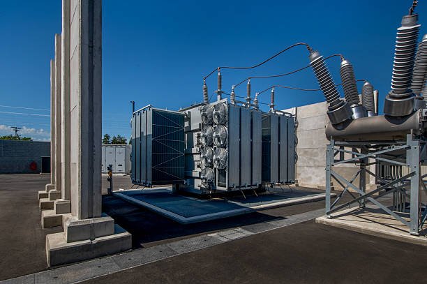
Future load growth is included in transformer sizing because electrical systems rarely remain static throughout the lifespan of the transformer. Over time, facilities expand, electrical demand increases, equipment is added, renewable energy systems are integrated, production capacity grows, population density changes, and new technologies such as electric vehicle charging, automation systems, and data centers significantly increase power consumption. Since power transformers are long-term infrastructure assets designed to operate for 20 to 40 years or more, engineers must ensure that transformers can safely and efficiently support not only present electrical demand but also anticipated future expansion.
If a transformer is sized only for current load conditions, it may quickly become overloaded as demand increases. Overloading causes excessive heating, insulation degradation, voltage instability, reduced efficiency, shortened equipment lifespan, and increased failure risk. Replacing or upgrading transformers after installation is often expensive, operationally disruptive, and technically challenging, especially in industrial plants, utility substations, commercial buildings, renewable energy systems, and critical infrastructure facilities. Therefore, future load growth is incorporated into transformer sizing to provide spare capacity, improve long-term reliability, reduce lifecycle cost, and support scalable electrical infrastructure development.
Modern electrical systems are experiencing faster load growth than ever before due to electrification, renewable energy integration, smart manufacturing, electric transportation, and digital infrastructure expansion. As a result, future growth planning has become one of the most important aspects of transformer engineering and power system design.
Future load growth is included in transformer sizing to ensure transformers can safely support increasing electrical demand, prevent premature overloading, reduce replacement costs, improve long-term reliability, and accommodate future expansion of electrical infrastructure.
Without future growth consideration, transformers may become undersized early in their service life, leading to overheating, reduced efficiency, operational instability, and costly infrastructure upgrades.
Transformers should only be sized according to current electrical demand because future load growth can always be handled later by adding new equipment easily.False
Transformer replacement and infrastructure upgrades are often expensive, disruptive, and technically complex, so future load growth must be considered during initial transformer sizing to ensure long-term reliability and scalability.
Why Transformer Sizing Must Consider the Future
Transformers are long-term electrical infrastructure assets.
Typical Transformer Service Life
| Transformer Type | Expected Lifespan |
|---|---|
| Distribution transformer | 20–35 years |
| Power transformer | 30–50 years |
| Industrial transformer | 25–40 years |
Electrical demand often changes significantly during this period.
What Is Future Load Growth?
Future load growth refers to expected increases in electrical demand over time.
Common Causes of Load Growth
| Cause | Impact on Demand |
|---|---|
| Facility expansion | Increased equipment load |
| Population growth | Higher utility demand |
| Renewable energy integration | Additional infrastructure |
| EV charging systems | Higher electrical consumption |
| Industrial automation | Increased power density |
Why Undersized Transformers Are Dangerous
Transformers operating beyond design capacity experience severe stress.
Overloading Risks
| Risk | Consequence |
|---|---|
| Excessive temperature rise | Insulation degradation |
| Voltage instability | Poor power quality |
| Reduced efficiency | Higher losses |
| Premature aging | Shortened lifespan |
Transformer Temperature and Overloading
Loading directly affects transformer heating.
Power Loss Equation
P_{loss}=I^2R
Where:
- (P_{loss}) = power loss
- (I) = current
- (R) = resistance
Higher future current dramatically increases heat generation.
Thermal Aging and Transformer Life
Transformer insulation aging accelerates rapidly at high temperature.
Thermal Aging Principle
Each increase in operating temperature significantly reduces insulation lifespan.
Why Future Capacity Prevents Premature Aging
| Proper Capacity Margin | Result |
|---|---|
| Lower operating temperature | Longer insulation life |
| Reduced overload stress | Improved reliability |
| Better cooling performance | Stable operation |
Economic Importance of Future Growth Planning
Transformer replacement is expensive and disruptive.
Costs of Early Replacement
| Cost Category | Impact |
|---|---|
| Equipment cost | High capital expense |
| Installation labor | Operational disruption |
| Downtime losses | Production interruption |
| Infrastructure modification | Additional construction cost |
Why Spare Capacity Is Economically Beneficial
Adding moderate spare capacity initially is often cheaper than future replacement.
Typical Future Growth Margins
Engineers usually include reserve capacity in transformer sizing.
Common Growth Margins
| Application | Typical Spare Capacity |
|---|---|
| Commercial buildings | 20–30% |
| Industrial facilities | 25–40% |
| Utility substations | Long-term planning margin |
| Data centers | Large scalability reserve |
Load Forecasting in Transformer Sizing
Future load growth requires demand forecasting.
Forecasting Factors
| Factor | Importance |
|---|---|
| Historical demand trends | Growth prediction |
| Economic development | Industrial expansion |
| Urbanization | Increased utility demand |
| Technology adoption | Emerging electrical loads |
Industrial Expansion and Transformer Growth
Industrial facilities often expand production capacity.
Industrial Growth Examples
| Expansion Type | Electrical Impact |
|---|---|
| Additional production lines | Increased motor load |
| Automation systems | Higher electronic load |
| HVAC expansion | Larger cooling demand |
Renewable Energy and Future Grid Expansion
Renewable integration increases transformer demand complexity.
Renewable Growth Drivers
| Renewable Technology | Transformer Impact |
|---|---|
| Solar farms | Variable generation |
| Wind energy | Collection system growth |
| Battery storage | Bidirectional loading |
Electric Vehicle Infrastructure Growth
EV charging is rapidly increasing electrical demand.
EV Charging Impact
| Charging Type | Power Demand |
|---|---|
| Residential charging | Moderate growth |
| Fast DC charging | Very high demand |
| Fleet charging stations | Major infrastructure expansion |
Data Centers and Digital Infrastructure
Data centers require scalable electrical systems.
Data Center Growth Factors
| Factor | Transformer Requirement |
|---|---|
| Server expansion | Increased continuous load |
| AI computing | Higher power density |
| Cooling systems | Additional electrical demand |
Urban Development and Utility Expansion
Utility transformers must support long-term urban growth.
Urban Load Growth Drivers
| Driver | Impact |
|---|---|
| Residential development | Distribution expansion |
| Commercial construction | Higher peak demand |
| Public transportation electrification | Increased infrastructure load |
Transformer Efficiency and Future Loading
Transformers operate most efficiently within optimal loading ranges.
Efficiency Equation
\eta=\frac{P{out}}{P{in}}\times100%
Why Proper Future Sizing Improves Efficiency
| Loading Condition | Efficiency Effect |
|---|---|
| Severe overload | Excessive copper losses |
| Moderate reserve margin | Stable efficiency |
| Extreme oversizing | High no-load losses |
Balancing Oversizing and Future Growth
Transformers should not be excessively oversized.
Risks of Excessive Oversizing
| Problem | Consequence |
|---|---|
| High no-load losses | Reduced efficiency |
| Increased capital cost | Poor investment return |
| Larger physical footprint | Installation challenges |
Smart Grids and Dynamic Load Growth
Modern smart grids experience changing load patterns.
Smart Grid Challenges
| Challenge | Transformer Impact |
|---|---|
| Distributed energy systems | Bidirectional power flow |
| Dynamic load balancing | Variable loading |
| Real-time demand response | Rapid demand fluctuations |
Harmonics and Future Electronic Loads
Future electrical systems contain more nonlinear loads.
Harmonic Sources
| Source | Application |
|---|---|
| Variable-frequency drives | Industrial automation |
| Solar inverters | Renewable energy |
| EV chargers | Transportation electrification |
Harmonic Distortion Equation
THD=\frac{\sqrt{V_2^2+V_3^2+\cdots}}{V_1}\times100%
Future harmonic growth may require additional transformer capacity.
Redundancy and Reliability Planning
Critical facilities require future reliability margins.
Critical Infrastructure Examples
| Facility | Reliability Requirement |
|---|---|
| Hospitals | Continuous operation |
| Data centers | Zero downtime |
| Utility substations | Grid stability |
Environmental and Cooling Considerations
Future growth affects transformer thermal loading.
Cooling Impacts
| Higher Future Load | Cooling Effect |
|---|---|
| Increased current | Higher temperature rise |
| Additional harmonics | Extra thermal stress |
| Continuous expansion | Reduced cooling margin |
Parallel Transformer Expansion Strategies
Future growth may involve parallel transformer operation.
Parallel Expansion Benefits
| Benefit | Result |
|---|---|
| Scalable capacity | Flexible expansion |
| Redundancy | Improved reliability |
| Maintenance flexibility | Reduced downtime |
Standards and Planning Guidelines
Transformer growth planning follows engineering standards.
Common Standards
| Standard | Organization |
|---|---|
| IEC 60076 | IEC |
| IEEE C57 | IEEE |
| NEC | National Electrical Code |
Smart Monitoring and Future Capacity Management
Modern transformers increasingly use intelligent monitoring.
Smart Monitoring Functions
| Technology | Benefit |
|---|---|
| Real-time load analysis | Capacity optimization |
| Predictive forecasting | Growth planning |
| Thermal modeling | Safe overload management |
Common Mistakes in Growth Planning
| Mistake | Consequence |
|---|---|
| Ignoring future expansion | Early transformer replacement |
| Excessive oversizing | Poor efficiency |
| Underestimating EV growth | Capacity shortage |
| Ignoring harmonics | Unexpected overheating |
Key Reasons Future Load Growth Is Included in Transformer Sizing
| Reason | Benefit |
|---|---|
| Long equipment lifespan | Supports future demand |
| Reduced replacement cost | Better lifecycle economics |
| Improved reliability | Lower overload risk |
| Expansion capability | Infrastructure flexibility |
| Better thermal management | Longer transformer life |
| Renewable integration | Future-ready operation |
Conclusion
Transformers are sized by analyzing load demand, voltage requirements, operating conditions, and expected future expansion. Engineers calculate the required kVA or MVA rating based on connected loads, load diversity, and duty cycles while also considering cooling capability and environmental factors. Proper transformer sizing ensures reliable performance, optimal efficiency, reduced operating costs, and long-term system stability.
FAQ
Q1: How are transformers sized for different loads?
Transformers are sized by calculating the total electrical load demand and selecting a transformer with the appropriate voltage rating, power capacity, and cooling capability.
Key considerations include:
Apparent power (kVA or MVA)
Input and output voltage
Load type and characteristics
Future load growth
Environmental and operating conditions
Correct sizing ensures reliable and efficient transformer performance.
Q2: Why is load type important in transformer sizing?
Different load types affect transformer performance differently.
Examples:
Resistive loads: Stable and predictable
Motor loads: High starting current requirements
Non-linear loads: Produce harmonics and extra heating
Transformers must be sized appropriately to handle these operational characteristics safely.
Q3: How do future expansion plans affect transformer sizing?
Engineers often include additional capacity to accommodate:
Future equipment installation
Increased production demand
Grid expansion
Renewable energy integration
Oversizing slightly can reduce future upgrade costs and improve system flexibility.
Q4: How does ambient temperature influence transformer sizing?
High ambient temperatures reduce transformer cooling efficiency.
In hot environments, transformers may require:
Higher power ratings
Enhanced cooling systems
Load derating adjustments
Proper thermal design prevents overheating and insulation damage.
Q5: Why are harmonics considered during transformer sizing?
Harmonics generated by electronic loads increase transformer heating and losses.
To manage harmonics, engineers may use:
K-rated transformers
Larger transformer capacity
Harmonic filtering systems
Ignoring harmonics can shorten transformer lifespan and reduce efficiency.
Q6: How is transformer sizing different for industrial applications?
Industrial transformers are often sized for:
Large motor starting currents
Heavy continuous loads
Variable-frequency drives (VFDs)
Harsh environmental conditions
These applications may require stronger insulation, cooling systems, and overload capability.
Q7: What happens if a transformer is incorrectly sized?
Improper sizing can lead to:
Overheating and insulation aging
Reduced efficiency
Voltage instability
Frequent overloads and failures
Higher operating costs
Accurate transformer sizing is essential for safe, reliable, and economical operation.
References
IEC 60076 – Power Transformers
https://webstore.iec.ch/publication/602
IEEE C57 Series – Transformer Application Standards
https://standards.ieee.org
Electrical Engineering Portal – Transformer Sizing Calculations
https://electrical-engineering-portal.com
CIGRE – Transformer Load and Thermal Studies
https://www.cigre.org
NEMA – Transformer Rating and Application Standards
https://www.nema.org
IEEE Power & Energy Society – Transformer Load Research
https://ieeexplore.ieee.org