Power transformers are among the most important components in modern electrical power systems. They enable efficient transmission and distribution of electricity by converting voltage levels between generation, transmission, and distribution networks. Designed to handle high voltages and large power capacities, power transformers ensure that electrical energy can be transported over long distances with minimal losses while maintaining system reliability and stability.
What Are Power Transformers?
![]()
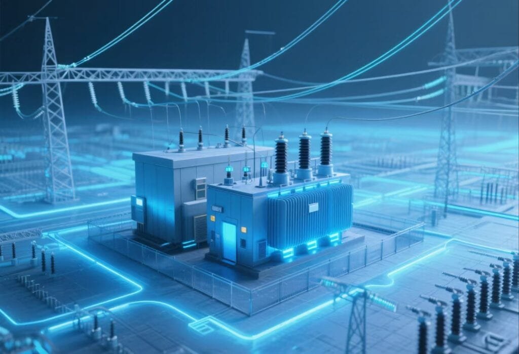
Electrical energy generated at power plants must travel long distances before reaching industrial facilities, commercial buildings, and residential consumers. During transmission and distribution, voltage levels must be adjusted efficiently to minimize energy losses and ensure safe operation. Without reliable voltage transformation, modern power systems would struggle to deliver electricity economically across vast geographic regions. This is where power transformers play a vital role.
Power transformers are among the most important assets in electrical power networks. They enable efficient transmission by stepping voltage up to high levels for long-distance transport and stepping it down at substations for safe utilization. Found in generating stations, transmission substations, industrial plants, renewable energy facilities, and utility networks, power transformers form the backbone of modern electrical infrastructure.
A power transformer is a static electrical device that transfers electrical energy between circuits through electromagnetic induction while changing voltage levels without altering frequency. Power transformers are primarily used in transmission and generation systems to step voltage up or down, improve transmission efficiency, reduce energy losses, and ensure reliable delivery of electrical power across the grid.
Because of their high efficiency, reliability, and long service life, power transformers are essential components of every modern power system.
Power transformers generate electrical energy and increase the total power available in a system.False
Power transformers do not generate power. They transfer electrical energy between circuits and change voltage levels while maintaining approximately the same power, minus small losses.
Understanding the Basic Function of a Power Transformer
A power transformer transfers electrical energy from one circuit to another using electromagnetic induction.
Operating Principle
When alternating current flows through the primary winding, it creates a changing magnetic field in the transformer core.
Energy Transfer Process
| Step | Description |
|---|---|
| Current enters primary winding | Magnetic flux created |
| Flux travels through core | Magnetic coupling occurs |
| Secondary winding intercepts flux | Voltage induced |
| Energy delivered to load | Power transferred |
This process occurs without direct electrical contact between windings.
Electromagnetic Induction
Power transformers operate according to the principle discovered by Michael Faraday.
Transformer Voltage Relationship
\frac{V_p}{V_s}=\frac{N_p}{N_s}
Where:
- (V_p) = primary voltage
- (V_s) = secondary voltage
- (N_p) = primary turns
- (N_s) = secondary turns
This relationship determines whether the transformer increases or decreases voltage.
Why Power Transformers Are Important
Modern power systems depend on efficient voltage conversion.
Benefits of High-Voltage Transmission
| Benefit | Result |
|---|---|
| Lower current | Reduced losses |
| Smaller conductors | Lower costs |
| Longer transmission distances | Improved efficiency |
| Better system performance | Increased reliability |
Power transformers make these advantages possible.
Step-Up and Step-Down Functions
Power transformers can either increase or decrease voltage.
Transformer Types by Function
| Type | Purpose |
|---|---|
| Step-up transformer | Increase voltage |
| Step-down transformer | Reduce voltage |
Both are essential in power systems.
Step-Up Power Transformers
Step-up transformers are typically installed at generating stations.
Purpose
They increase generator voltage before power enters transmission networks.
Example
| Location | Voltage |
|---|---|
| Generator output | 13.8 kV |
| Transmission system | 230 kV |
The transformer raises voltage to reduce transmission losses.
Step-Down Power Transformers
Step-down transformers reduce voltage at substations.
Purpose
They prepare electricity for distribution and utilization.
Example
| Stage | Voltage |
|---|---|
| Transmission network | 230 kV |
| Distribution network | 33 kV |
| Consumer supply | 400 V |
Several transformer stages may be used before electricity reaches end users.
Main Components of a Power Transformer
Power transformers consist of several critical components.
Major Components
| Component | Function |
|---|---|
| Magnetic core | Flux path |
| Windings | Voltage transformation |
| Insulation system | Electrical separation |
| Transformer oil | Cooling and insulation |
| Bushings | External connections |
| Cooling equipment | Heat removal |
Each component contributes to safe and reliable operation.
Transformer Core
The core provides a low-reluctance path for magnetic flux.
Core Functions
| Function | Benefit |
|---|---|
| Flux guidance | Efficient energy transfer |
| Loss reduction | Improved efficiency |
| Mechanical support | Structural stability |
Modern cores use laminated electrical steel to minimize losses.
Transformer Windings
Windings carry electrical current and enable voltage conversion.
Winding Types
| Winding | Purpose |
|---|---|
| Primary winding | Receives power |
| Secondary winding | Delivers power |
| Tertiary winding | Auxiliary functions |
The number of turns determines voltage ratio.
Insulation System
The insulation system prevents electrical breakdown.
Common Insulation Materials
| Material | Application |
|---|---|
| Cellulose paper | Winding insulation |
| Pressboard | Structural insulation |
| Mineral oil | Dielectric medium |
Insulation quality greatly influences transformer life expectancy.
Transformer Oil
Most large power transformers use insulating oil.
Functions
| Function | Purpose |
|---|---|
| Electrical insulation | Prevent flashover |
| Heat transfer | Cooling |
| Arc suppression | Fault protection |
Oil condition is a key indicator of transformer health.
Cooling Systems
Transformers generate heat due to losses.
Common Cooling Methods
| Method | Meaning |
|---|---|
| ONAN | Oil Natural Air Natural |
| ONAF | Oil Natural Air Forced |
| OFAF | Oil Forced Air Forced |
| OFWF | Oil Forced Water Forced |
Cooling systems maintain acceptable operating temperatures.
Types of Power Transformers
Power transformers can be classified in several ways.
By Application
| Type | Application |
|---|---|
| Generator transformer | Power stations |
| Transmission transformer | High-voltage networks |
| Substation transformer | Grid interconnection |
| Industrial transformer | Manufacturing facilities |
Each design serves a specific purpose.
By Installation Location
| Type | Description |
|---|---|
| Indoor transformer | Building installation |
| Outdoor transformer | Substation installation |
Environmental conditions influence design requirements.
By Cooling Method
| Cooling Type | Typical Rating |
|---|---|
| Dry-type | Lower ratings |
| Oil-immersed | Medium to very high ratings |
Most utility power transformers are oil-immersed.
Typical Voltage Levels
Power transformers operate across a wide range of voltages.
Common Voltage Classes
| Application | Voltage |
|---|---|
| Generation | 11–25 kV |
| Sub-transmission | 33–132 kV |
| Transmission | 220–765 kV |
| Ultra-high voltage | Above 765 kV |
Transformer design varies with voltage class.
Efficiency of Power Transformers
Power transformers are among the most efficient electrical devices.
Typical Efficiency
| Transformer Size | Efficiency |
|---|---|
| Medium power transformer | 98–99% |
| Large utility transformer | 99%+ |
Losses are generally very small compared to transferred power.
Sources of Transformer Losses
Core Losses
| Type | Cause |
|---|---|
| Hysteresis loss | Magnetic reversal |
| Eddy current loss | Induced currents |
Core losses occur continuously.
Copper Losses
Copper losses occur in windings.
Formula
P_{Cu}=I^2R
Where:
- (P_{Cu}) = copper loss
- (I) = current
- (R) = winding resistance
Copper losses increase with load.
Applications of Power Transformers
Power transformers are used throughout the electrical industry.
Common Applications
| Sector | Use |
|---|---|
| Utilities | Transmission and distribution |
| Power generation | Voltage step-up |
| Renewable energy | Grid connection |
| Industrial plants | Process power |
| Transportation | Railway systems |
Their versatility makes them indispensable.
Renewable Energy Applications
Renewable energy facilities depend heavily on transformers.
Examples
| Facility | Transformer Role |
|---|---|
| Solar farms | Voltage step-up |
| Wind farms | Grid integration |
| Battery storage systems | Power conversion |
Transformers facilitate efficient renewable energy transmission.
Reliability and Service Life
Power transformers are designed for long-term operation.
Typical Service Life
| Condition | Expected Life |
|---|---|
| Well-maintained unit | 30–50 years |
| Premium utility transformer | 50+ years |
Proper maintenance significantly extends lifespan.
Monitoring and Maintenance
Utilities continuously monitor transformer condition.
Common Monitoring Methods
| Method | Purpose |
|---|---|
| Dissolved Gas Analysis (DGA) | Fault detection |
| Oil testing | Insulation assessment |
| Temperature monitoring | Thermal protection |
| Partial discharge monitoring | Early warning |
Preventive maintenance reduces failure risk.
Advantages of Power Transformers
| Advantage | Benefit |
|---|---|
| High efficiency | Low operating cost |
| Reliable operation | Improved grid stability |
| Long service life | Reduced lifecycle cost |
| Flexible voltage conversion | Broad applicability |
| Scalable design | Suitable for all voltage levels |
These advantages make power transformers essential to modern electrical infrastructure.
What Are the Main Components of a Power Transformer?
Power transformers are among the most critical assets in electrical power systems, enabling efficient voltage conversion for generation, transmission, and distribution networks. Their ability to operate continuously for decades under demanding electrical, thermal, and environmental conditions depends on a carefully engineered combination of components. Each component performs a specific function that contributes to the transformer's efficiency, reliability, safety, and service life.
Although power transformers may vary in size, voltage class, and application, their fundamental construction follows similar principles. From the magnetic core that guides flux to the insulation system that prevents electrical breakdown, every element is designed to ensure safe and efficient energy transfer. Understanding these components helps engineers, operators, and asset managers better evaluate transformer performance, maintenance requirements, and operational reliability.
The main components of a power transformer include the magnetic core, primary and secondary windings, insulation system, transformer oil, tank, cooling system, bushings, tap changer, conservator, breather, monitoring instruments, and protection devices. Together, these components enable efficient voltage transformation, heat dissipation, electrical insulation, and long-term operational reliability.
Each component plays a vital role in maintaining transformer performance throughout its service life.
The magnetic core is the only essential component in a power transformer, while other parts mainly serve cosmetic or secondary purposes.False
A power transformer requires multiple critical components, including windings, insulation systems, cooling equipment, bushings, and protective devices, all of which are essential for safe and reliable operation.
Overview of Power Transformer Construction
A power transformer consists of both active and auxiliary components.
Major Component Categories
| Category | Function |
|---|---|
| Active components | Energy conversion |
| Insulation components | Electrical protection |
| Cooling components | Heat removal |
| Mechanical components | Structural support |
| Monitoring and protection systems | Reliability and safety |
Each category contributes to overall transformer performance.
Magnetic Core
The magnetic core is the heart of the transformer.
Primary Function
The core provides a low-reluctance path for magnetic flux generated by the windings.
Core Responsibilities
| Function | Benefit |
|---|---|
| Flux guidance | Efficient energy transfer |
| Magnetic coupling | Voltage transformation |
| Loss reduction | Higher efficiency |
Without the core, efficient electromagnetic induction would not occur.
Core Construction
Modern transformer cores are typically made from laminated electrical steel.
Benefits of Laminations
| Benefit | Result |
|---|---|
| Reduced eddy currents | Lower losses |
| Improved efficiency | Reduced heating |
| Better performance | Longer life |
Core design has a major influence on transformer efficiency.
Transformer Windings
Windings are responsible for transferring electrical energy.
Main Winding Types
| Winding | Function |
|---|---|
| Primary winding | Receives input power |
| Secondary winding | Delivers output power |
| Tertiary winding | Auxiliary functions |
The winding ratio determines the voltage transformation ratio.
Voltage Ratio Relationship
\frac{V_p}{V_s}=\frac{N_p}{N_s}
Where:
- (V_p) = primary voltage
- (V_s) = secondary voltage
- (N_p) = primary turns
- (N_s) = secondary turns
This equation forms the basis of transformer operation.
Winding Materials
Most transformer windings are manufactured from copper or aluminum.
Material Comparison
| Property | Copper | Aluminum |
|---|---|---|
| Conductivity | Higher | Lower |
| Weight | Heavier | Lighter |
| Cost | Higher | Lower |
Both materials are widely used depending on application requirements.
Insulation System
The insulation system prevents electrical breakdown between energized components.
Primary Functions
| Function | Purpose |
|---|---|
| Electrical separation | Safety |
| Voltage withstand capability | Reliability |
| Mechanical support | Structural integrity |
Transformer life largely depends on insulation condition.
Common Insulation Materials
| Material | Application |
|---|---|
| Cellulose paper | Winding insulation |
| Pressboard | Structural insulation |
| Epoxy materials | Special applications |
| Transformer oil | Dielectric insulation |
These materials work together as a complete insulation system.
Transformer Oil
Most large power transformers use insulating oil.
Functions of Transformer Oil
| Function | Purpose |
|---|---|
| Electrical insulation | Prevent flashover |
| Heat transfer | Cooling |
| Arc suppression | Fault protection |
Oil quality directly affects transformer reliability.
Characteristics of Transformer Oil
| Property | Importance |
|---|---|
| Dielectric strength | High |
| Thermal conductivity | High |
| Oxidation resistance | High |
Regular oil testing is essential for condition monitoring.
Transformer Tank
The tank houses and protects internal components.
Tank Functions
| Function | Benefit |
|---|---|
| Mechanical protection | Equipment security |
| Oil containment | Insulation support |
| Environmental protection | Long-term durability |
Large power transformer tanks are fabricated from heavy-duty steel.
Tank Design Considerations
| Factor | Importance |
|---|---|
| Structural strength | High |
| Corrosion resistance | High |
| Leak prevention | Critical |
Proper tank design contributes to long service life.
Cooling System
Transformers generate heat due to electrical losses.
Sources of Heat
| Source | Type |
|---|---|
| Core losses | No-load losses |
| Winding losses | Load losses |
Effective cooling prevents excessive temperatures.
Common Cooling Methods
| Cooling Class | Meaning |
|---|---|
| ONAN | Oil Natural Air Natural |
| ONAF | Oil Natural Air Forced |
| OFAF | Oil Forced Air Forced |
| OFWF | Oil Forced Water Forced |
Larger transformers typically use more advanced cooling systems.
Cooling Equipment Components
| Component | Function |
|---|---|
| Radiators | Heat dissipation |
| Cooling fans | Forced-air cooling |
| Oil pumps | Oil circulation |
| Heat exchangers | Enhanced cooling |
Cooling equipment significantly affects transformer loading capability.
Bushings
Bushings provide insulated pathways for conductors entering and leaving the transformer.
Main Functions
| Function | Purpose |
|---|---|
| Electrical connection | Current transfer |
| Voltage insulation | Safety |
| Environmental sealing | Protection |
Bushings are among the most critical external transformer components.
Types of Bushings
| Type | Application |
|---|---|
| Porcelain bushings | Traditional designs |
| Composite bushings | Modern installations |
| Oil-filled bushings | High-voltage applications |
Selection depends on voltage level and environmental conditions.
Tap Changer
Power systems experience voltage fluctuations that require adjustment.
Purpose of Tap Changers
| Function | Benefit |
|---|---|
| Voltage regulation | Stable output |
| Network support | Improved performance |
| Operational flexibility | Enhanced control |
Tap changers modify the transformer turns ratio.
Tap Changer Types
| Type | Characteristics |
|---|---|
| Off-circuit tap changer | Requires shutdown |
| On-load tap changer (OLTC) | Operates under load |
Most utility power transformers use OLTCs.
Conservator Tank
Oil expands and contracts with temperature changes.
Conservator Functions
| Function | Benefit |
|---|---|
| Oil expansion accommodation | Pressure control |
| Reduced oil oxidation | Longer oil life |
| Moisture protection | Improved insulation |
Many large transformers use conservator systems.
Breather
The breather prevents moisture from entering the transformer.
How It Works
Air entering the conservator passes through a drying medium.
Typical Drying Material
| Material | Purpose |
|---|---|
| Silica gel | Moisture absorption |
This helps preserve insulation quality.
Monitoring Instruments
Modern transformers contain numerous monitoring devices.
Common Instruments
| Instrument | Purpose |
|---|---|
| Oil level indicator | Fluid monitoring |
| Temperature indicator | Thermal monitoring |
| Pressure gauge | Pressure control |
| Winding temperature monitor | Hot-spot protection |
Continuous monitoring improves reliability.
Protection Devices
Protection systems help prevent catastrophic failures.
Essential Protective Equipment
| Device | Function |
|---|---|
| Buchholz relay | Gas fault detection |
| Pressure relief device | Overpressure protection |
| Differential relay | Internal fault protection |
| Sudden pressure relay | Fault detection |
These devices enhance transformer safety.
Buchholz Relay
The Buchholz relay is widely used in oil-filled transformers.
Functions
| Condition | Response |
|---|---|
| Minor internal fault | Alarm |
| Severe internal fault | Trip |
It provides early warning of internal problems.
Pressure Relief Device
Internal faults may generate excessive pressure.
Purpose
| Function | Benefit |
|---|---|
| Pressure release | Tank protection |
| Explosion prevention | Safety improvement |
These devices are critical for large transformers.
Transformer Losses and Related Components
Transformer components are designed to minimize losses.
Copper Loss Formula
P_{Cu}=I^2R
Where:
- (P_{Cu}) = copper loss
- (I) = current
- (R) = winding resistance
Proper winding design helps reduce these losses.
Core Loss Components
| Loss Type | Cause |
|---|---|
| Hysteresis loss | Magnetic reversal |
| Eddy current loss | Induced currents |
Core design directly affects these losses.
Summary of Main Components
| Component | Primary Function |
|---|---|
| Magnetic core | Magnetic flux path |
| Windings | Voltage transformation |
| Insulation system | Electrical separation |
| Transformer oil | Cooling and insulation |
| Tank | Mechanical protection |
| Cooling system | Heat removal |
| Bushings | Electrical connection |
| Tap changer | Voltage regulation |
| Conservator | Oil expansion control |
| Breather | Moisture prevention |
| Monitoring instruments | Condition monitoring |
| Protection devices | Fault protection |
How Do Power Transformers Work?
Electricity generated at power plants must be transmitted efficiently over long distances before it reaches homes, businesses, and industrial facilities. However, transmitting large amounts of power at low voltage would result in excessive current flow and significant energy losses. To solve this challenge, power systems rely on power transformers to increase voltage for transmission and decrease voltage for safe utilization. These devices make modern electrical grids practical, efficient, and reliable.
Power transformers operate without any moving parts and can achieve efficiencies exceeding 99%. Their operation is based on the principle of electromagnetic induction, allowing electrical energy to be transferred between circuits while changing voltage levels and maintaining the same frequency. Understanding how power transformers work provides valuable insight into one of the most important technologies in electrical power engineering.
Power transformers work by transferring electrical energy between two or more windings through electromagnetic induction. When alternating current flows through the primary winding, it creates a changing magnetic flux in the transformer core. This changing flux induces a voltage in the secondary winding, allowing energy to be transferred while increasing or decreasing voltage according to the transformer turns ratio.
This simple but highly effective principle has enabled the development of modern transmission and distribution networks worldwide.
Power transformers transfer electricity through direct electrical contact between the primary and secondary windings.False
Power transformers transfer energy through electromagnetic induction. The primary and secondary windings are electrically isolated and connected only through a shared magnetic field in the transformer core.
The Basic Principle of Transformer Operation
Power transformers operate according to the principle of electromagnetic induction.
What Is Electromagnetic Induction?
Electromagnetic induction occurs when a changing magnetic field produces a voltage in a conductor.
Energy Transfer Process
| Step | Description |
|---|---|
| AC current enters primary winding | Magnetic field generated |
| Magnetic flux develops in core | Flux links windings |
| Flux changes continuously | Induced voltage created |
| Secondary winding receives voltage | Power delivered to load |
This process enables energy transfer without direct electrical contact.
Faraday's Law of Electromagnetic Induction
Transformer operation is based on the discoveries of Michael Faraday.
Fundamental Induction Relationship
The induced voltage is proportional to the rate of change of magnetic flux.
Key Concept
| Variable | Effect |
|---|---|
| Magnetic flux | Determines induced voltage |
| Frequency | Influences flux variation |
| Number of turns | Affects voltage magnitude |
These relationships form the basis of transformer design.
Main Components Involved in Operation
Several transformer components work together during energy transfer.
Active Components
| Component | Function |
|---|---|
| Primary winding | Receives input power |
| Secondary winding | Delivers output power |
| Magnetic core | Guides magnetic flux |
These components perform the fundamental transformation process.
The Role of the Primary Winding
The primary winding is connected to the power source.
Function
When alternating current flows through the winding, a magnetic field is produced.
Primary Winding Process
| Step | Result |
|---|---|
| Voltage applied | Current flows |
| Current flows | Magnetic field created |
| Alternating current changes direction | Flux varies continuously |
This changing flux is essential for transformer operation.
The Role of the Magnetic Core
The magnetic core provides a low-reluctance path for flux.
Why the Core Is Important
| Function | Benefit |
|---|---|
| Concentrates magnetic flux | Higher efficiency |
| Improves coupling | Better energy transfer |
| Reduces losses | Lower operating cost |
Without a core, transformer efficiency would be significantly reduced.
Core Construction
Modern transformer cores are built from laminated electrical steel.
Benefits of Laminations
| Benefit | Result |
|---|---|
| Reduced eddy currents | Lower losses |
| Lower heating | Improved efficiency |
| Better performance | Longer service life |
Core design has a major impact on transformer efficiency.
The Role of the Secondary Winding
The secondary winding receives energy from the magnetic field.
Process
The changing magnetic flux induces a voltage in the secondary winding.
Secondary Winding Operation
| Step | Result |
|---|---|
| Flux links secondary turns | Voltage induced |
| Load connected | Current flows |
| Energy delivered | Useful work performed |
This is how power is transferred to the load.
Transformer Turns Ratio
Voltage transformation depends on the number of turns in each winding.
Voltage Ratio Equation
\frac{V_p}{V_s}=\frac{N_p}{N_s}
Where:
- (V_p) = primary voltage
- (V_s) = secondary voltage
- (N_p) = primary winding turns
- (N_s) = secondary winding turns
The turns ratio determines whether voltage is increased or decreased.
Step-Up Transformer Operation
A step-up transformer increases voltage.
Configuration
| Characteristic | Condition |
|---|---|
| Secondary turns | Greater than primary turns |
| Output voltage | Higher than input voltage |
| Output current | Lower than input current |
These transformers are commonly used at power plants.
Example
| Parameter | Value |
|---|---|
| Primary voltage | 13.8 kV |
| Secondary voltage | 230 kV |
The transformer raises voltage for efficient transmission.
Step-Down Transformer Operation
A step-down transformer decreases voltage.
Configuration
| Characteristic | Condition |
|---|---|
| Secondary turns | Fewer than primary turns |
| Output voltage | Lower than input voltage |
| Output current | Higher than input current |
These transformers are used in substations and distribution systems.
Power Conservation in Transformers
Transformers do not create energy.
Power Relationship
Ignoring losses:
P{in}=P{out}
Or:
V_pI_p=V_sI_s
This means an increase in voltage results in a proportional decrease in current.
Why High Voltage Reduces Losses
Electrical transmission losses depend on current.
Copper Loss Formula
P_{loss}=I^2R
Where:
- (P_{loss}) = power loss
- (I) = current
- (R) = conductor resistance
Reducing current dramatically lowers transmission losses.
Example of Transmission Efficiency
| Voltage Level | Current Required | Relative Losses |
|---|---|---|
| Low voltage | High current | High losses |
| High voltage | Low current | Low losses |
This is why transformers are indispensable in power systems.
Transformer Frequency
Transformers do not change frequency.
Frequency Relationship
| Parameter | Result |
|---|---|
| Input frequency | Same as output frequency |
| Voltage | May change |
| Current | May change |
| Power frequency | Unchanged |
The transformer only alters voltage and current relationships.
Transformer Efficiency
Power transformers are highly efficient devices.
Typical Efficiencies
| Transformer Type | Efficiency |
|---|---|
| Medium-sized power transformer | 98–99% |
| Large utility transformer | 99%+ |
Only a small portion of energy is lost.
Sources of Transformer Losses
Core Losses
Core losses occur whenever the transformer is energized.
| Loss Type | Cause |
|---|---|
| Hysteresis loss | Magnetic reversal |
| Eddy current loss | Induced currents |
These losses are largely independent of load.
Copper Losses
Copper losses occur due to winding resistance.
Characteristics
| Condition | Copper Loss |
|---|---|
| No load | Minimal |
| Full load | Maximum |
Copper losses increase with current.
Cooling During Operation
Transformer losses generate heat.
Cooling Functions
| Function | Purpose |
|---|---|
| Heat removal | Prevent overheating |
| Temperature control | Extend insulation life |
| Reliability enhancement | Improve performance |
Effective cooling is critical for large power transformers.
Typical Cooling Methods
| Cooling Class | Description |
|---|---|
| ONAN | Oil Natural Air Natural |
| ONAF | Oil Natural Air Forced |
| OFAF | Oil Forced Air Forced |
| OFWF | Oil Forced Water Forced |
Larger transformers generally require more advanced cooling systems.
Real-World Example of Transformer Operation
Consider a generating station transformer.
Example
| Parameter | Value |
|---|---|
| Generator voltage | 15 kV |
| Transmission voltage | 400 kV |
| Transformer type | Step-up |
The transformer increases voltage to minimize transmission losses.
At the receiving substation:
| Parameter | Value |
|---|---|
| Transmission voltage | 400 kV |
| Distribution voltage | 33 kV |
| Transformer type | Step-down |
Additional transformers further reduce voltage before electricity reaches consumers.
Applications of Power Transformers
Power transformers are used throughout the electrical industry.
Common Applications
| Sector | Application |
|---|---|
| Power generation | Voltage step-up |
| Transmission networks | Interconnection |
| Distribution substations | Voltage reduction |
| Renewable energy projects | Grid connection |
| Industrial facilities | Process power |
Their versatility makes them essential to modern infrastructure.
Advantages of Transformer Operation
| Advantage | Benefit |
|---|---|
| No moving parts | High reliability |
| High efficiency | Low operating cost |
| Electrical isolation | Improved safety |
| Flexible voltage conversion | Broad applicability |
| Long service life | Reduced lifecycle cost |
These characteristics contribute to widespread use.
Summary of the Operating Process
| Step | Action |
|---|---|
| AC voltage applied to primary winding | Current flows |
| Current generates magnetic flux | Core magnetized |
| Flux links secondary winding | Voltage induced |
| Load connected | Current delivered |
| Energy transferred | Useful power supplied |
This sequence continuously repeats while the transformer is energized.
Why Are Power Transformers Essential for Voltage Conversion?
Electricity generated at power stations must travel hundreds or even thousands of kilometers before reaching homes, businesses, and industrial facilities. If electrical energy were transmitted at low voltage over such distances, the resulting high current would cause significant power losses, excessive conductor heating, and inefficient system operation. To overcome these challenges, power systems rely on power transformers to convert voltage levels efficiently at various stages of generation, transmission, and distribution.
Voltage conversion is one of the most important functions in modern electrical networks. By increasing voltage for transmission and reducing it for utilization, power transformers make long-distance power delivery economically viable and technically practical. Without transformers, today's interconnected power grids, renewable energy systems, and industrial power networks would not be possible.
Power transformers are essential for voltage conversion because they efficiently increase or decrease AC voltage levels through electromagnetic induction. By stepping voltage up for transmission, transformers reduce current and minimize energy losses. By stepping voltage down for distribution and consumption, they ensure that electricity can be safely and effectively used by industrial, commercial, and residential loads.
This ability to transform voltage efficiently is fundamental to the operation of modern power systems.
Power transformers are primarily used to generate electricity, while voltage conversion is only a secondary function.False
Power transformers do not generate electricity. Their primary purpose is to transfer electrical energy between circuits while changing voltage levels efficiently through electromagnetic induction.
Why Voltage Conversion Is Necessary
Electrical power systems operate at multiple voltage levels.
The Challenge
Power plants generate electricity at relatively moderate voltages, but long-distance transmission requires much higher voltages.
Typical Voltage Levels
| Power System Stage | Typical Voltage |
|---|---|
| Generator output | 11–25 kV |
| Transmission network | 132–765 kV |
| Distribution network | 11–33 kV |
| Consumer utilization | 120–400 V |
Transformers enable smooth transitions between these voltage levels.
The Relationship Between Voltage, Current, and Power
Electrical power depends on both voltage and current.
Basic Power Equation
P=VI
Where:
- (P) = power
- (V) = voltage
- (I) = current
For a given power level, increasing voltage reduces current.
Example
| Voltage | Current Required for 10 MW |
|---|---|
| 10 kV | 1000 A |
| 100 kV | 100 A |
| 400 kV | 25 A |
Higher voltage dramatically reduces current requirements.
Why Lower Current Matters
Transmission losses are largely determined by conductor current.
Copper Loss Formula
P_{loss}=I^2R
Where:
- (P_{loss}) = conductor loss
- (I) = current
- (R) = conductor resistance
Because current is squared, even small reductions in current produce substantial loss reductions.
Impact of Current Reduction
| Current Change | Relative Loss Change |
|---|---|
| 50% reduction | 75% loss reduction |
| 75% reduction | 94% loss reduction |
| 90% reduction | 99% loss reduction |
This is one of the main reasons voltage conversion is essential.
How Power Transformers Perform Voltage Conversion
Power transformers operate through electromagnetic induction.
Basic Process
| Step | Action |
|---|---|
| AC voltage applied to primary winding | Magnetic flux generated |
| Flux passes through core | Energy transferred |
| Secondary winding receives induced voltage | Voltage converted |
The voltage level depends on the winding turns ratio.
Voltage Transformation Equation
\frac{V_p}{V_s}=\frac{N_p}{N_s}
Where:
- (V_p) = primary voltage
- (V_s) = secondary voltage
- (N_p) = primary turns
- (N_s) = secondary turns
The turns ratio determines the output voltage.
Step-Up Voltage Conversion
Step-up transformers increase voltage.
Why Step-Up Conversion Is Needed
Power plants typically generate electricity at voltages that are too low for efficient transmission.
Example
| Location | Voltage |
|---|---|
| Generator output | 15 kV |
| Transmission network | 400 kV |
A step-up transformer raises the voltage before transmission.
Benefits of Step-Up Conversion
| Benefit | Result |
|---|---|
| Lower current | Reduced losses |
| Smaller conductors | Lower infrastructure costs |
| Greater transmission distance | Improved efficiency |
Step-up transformers are critical at generating stations.
Step-Down Voltage Conversion
Step-down transformers reduce voltage to usable levels.
Why Step-Down Conversion Is Needed
Transmission voltages are far too high for industrial equipment and consumer devices.
Example
| Stage | Voltage |
|---|---|
| Transmission system | 400 kV |
| Distribution network | 33 kV |
| End user supply | 400 V |
Multiple transformer stages are often used.
Benefits of Step-Down Conversion
| Benefit | Result |
|---|---|
| Improved safety | Lower risk |
| Equipment compatibility | Proper operation |
| Efficient utilization | Reliable power delivery |
This ensures electricity can be used safely and effectively.
Power Conservation During Voltage Conversion
Transformers do not create energy.
Ideal Transformer Relationship
V_pI_p=V_sI_s
This means:
| Parameter | Effect |
|---|---|
| Voltage increases | Current decreases |
| Voltage decreases | Current increases |
| Power remains approximately constant | Energy conserved |
Only small losses occur during conversion.
Transformer Efficiency
Power transformers are extremely efficient.
Typical Efficiencies
| Transformer Type | Efficiency |
|---|---|
| Medium power transformer | 98–99% |
| Large utility transformer | Over 99% |
Few electrical devices achieve such high efficiency.
Voltage Conversion Across the Power Grid
Transformers are used repeatedly throughout the electrical network.
Typical Voltage Conversion Chain
| Stage | Transformer Function |
|---|---|
| Generation | Step-up |
| Transmission interconnection | Voltage adjustment |
| Substation | Step-down |
| Distribution | Further step-down |
| End-user service | Final voltage reduction |
Each stage serves a specific purpose.
Supporting Long-Distance Transmission
Modern power systems depend on long-distance energy transport.
Challenges Without Voltage Conversion
| Problem | Impact |
|---|---|
| High current | Excessive losses |
| Large conductors | Increased cost |
| Limited transmission distance | Reduced efficiency |
Transformers solve these problems effectively.
Enabling Large Interconnected Power Systems
National and regional grids require multiple voltage levels.
Benefits
| Benefit | Description |
|---|---|
| Resource sharing | Improved reliability |
| Economic dispatch | Lower operating costs |
| Renewable integration | Better flexibility |
Voltage conversion enables these interconnected systems.
Supporting Renewable Energy Integration
Renewable energy projects depend heavily on transformers.
Solar Power Example
| Stage | Voltage |
|---|---|
| Solar inverter output | 400–800 V |
| Collection system | 33 kV |
| Transmission grid | 132–400 kV |
Transformers connect renewable generation to the grid.
Wind Power Example
| Stage | Voltage |
|---|---|
| Wind turbine generator | 690 V |
| Wind farm collection system | 33–66 kV |
| Transmission network | 132–400 kV |
Without transformers, large-scale renewable integration would be impractical.
Industrial Power Applications
Industrial facilities require customized voltage levels.
Examples
| Industry | Typical Voltage |
|---|---|
| Manufacturing | 400 V–33 kV |
| Mining | 6.6–33 kV |
| Petrochemical | 11–33 kV |
Transformers provide the necessary voltage conversion.
Economic Importance of Voltage Conversion
Efficient voltage conversion significantly reduces system costs.
Financial Benefits
| Benefit | Economic Impact |
|---|---|
| Reduced losses | Lower energy costs |
| Smaller conductors | Lower capital cost |
| Increased transmission capability | Better asset utilization |
The savings achieved over decades of operation are enormous.
Consequences of Inadequate Voltage Conversion
Without proper transformer infrastructure:
| Problem | Result |
|---|---|
| High losses | Reduced efficiency |
| Voltage instability | Poor power quality |
| Equipment incompatibility | Operational issues |
| Increased costs | Reduced profitability |
Reliable voltage conversion is therefore essential.
Summary of Why Transformers Are Essential
| Reason | Benefit |
|---|---|
| Voltage step-up | Efficient transmission |
| Voltage step-down | Safe utilization |
| Loss reduction | Improved efficiency |
| Grid interconnection | Enhanced reliability |
| Renewable integration | Sustainable energy support |
These benefits make transformers indispensable.
Where Are Power Transformers Commonly Used?
Modern society depends on a continuous and reliable supply of electricity. From power generation stations and transmission networks to factories, data centers, and renewable energy facilities, electrical energy must be transferred efficiently at the appropriate voltage level. Since different stages of the power system require different voltages, power transformers are essential for converting voltage levels and enabling safe, economical, and efficient energy delivery.
Power transformers are among the most widely deployed pieces of electrical equipment in the world. Their applications extend far beyond traditional utility substations. Today, they are found in nearly every sector that generates, transmits, distributes, or consumes large amounts of electrical energy. Understanding where power transformers are commonly used helps illustrate their critical role in modern infrastructure.
Power transformers are commonly used in power generation stations, transmission substations, distribution networks, renewable energy facilities, industrial plants, commercial buildings, transportation systems, data centers, mining operations, and utility interconnection points. Their primary function is to convert voltage levels efficiently while supporting reliable power delivery throughout the electrical grid.
Without power transformers, modern electrical networks would be unable to operate effectively.
Power transformers are only used in electrical substations and have no significant role in industrial or renewable energy applications.False
Power transformers are widely used in many sectors, including power generation, renewable energy, industrial manufacturing, transportation systems, mining operations, and large commercial facilities.
Power Generation Stations
One of the most important applications of power transformers is in power generation facilities.
Why Transformers Are Needed
Generators typically produce electricity at medium voltages that are too low for efficient transmission.
Typical Generator Voltages
| Generation Type | Typical Voltage |
|---|---|
| Thermal power plant | 11–25 kV |
| Hydroelectric plant | 11–22 kV |
| Nuclear power plant | 18–27 kV |
Transformers increase voltage before electricity enters the transmission network.
Generator Step-Up Transformers (GSUs)
Generator step-up transformers connect generating units to high-voltage transmission systems.
Example
| Equipment | Voltage |
|---|---|
| Generator output | 15 kV |
| Transmission system | 400 kV |
The transformer raises voltage to reduce transmission losses.
Transmission Networks
High-voltage transmission systems depend heavily on power transformers.
Purpose
Transmission transformers interconnect different voltage levels within the grid.
Common Transmission Voltages
| Voltage Class | Application |
|---|---|
| 132 kV | Regional transmission |
| 220 kV | Bulk power transfer |
| 400 kV | Long-distance transmission |
| 765 kV | Extra-high-voltage systems |
Transformers enable efficient energy movement across large distances.
Transmission Substations
Transmission substations use power transformers for voltage conversion and grid interconnection.
Functions
| Function | Purpose |
|---|---|
| Voltage transformation | Network integration |
| System interconnection | Reliability enhancement |
| Load balancing | Operational efficiency |
These substations form the backbone of modern electrical grids.
Distribution Networks
Before electricity reaches consumers, voltage must be reduced.
Distribution Transformer Chain
| Stage | Voltage |
|---|---|
| Transmission | 220–400 kV |
| Sub-transmission | 33–132 kV |
| Distribution | 11–33 kV |
| End-user supply | 120–400 V |
Power transformers perform the critical intermediate conversion stages.
Utility Distribution Substations
Distribution substations use power transformers to prepare electricity for local delivery.
Benefits
| Benefit | Result |
|---|---|
| Safe voltage levels | Consumer protection |
| Improved reliability | Better service quality |
| Efficient distribution | Reduced losses |
These transformers operate continuously throughout the year.
Renewable Energy Facilities
Renewable energy systems require multiple stages of voltage conversion.
Solar Power Plants
Solar facilities generate power at relatively low voltages.
Typical Voltage Path
| Stage | Voltage |
|---|---|
| Solar inverter output | 400–800 V |
| Collection system | 11–33 kV |
| Transmission grid | 132–400 kV |
Transformers connect solar generation to the grid.
Wind Farms
Wind turbines also require voltage transformation.
Typical Wind Farm Configuration
| Stage | Voltage |
|---|---|
| Turbine generator | 690 V |
| Collection network | 33–66 kV |
| Transmission connection | 132–400 kV |
Power transformers are essential for efficient wind energy integration.
Renewable Energy Voltage Conversion
The voltage conversion process follows electromagnetic induction principles.
Transformer Voltage Ratio
\frac{V_p}{V_s}=\frac{N_p}{N_s}
Where:
- (V_p) = primary voltage
- (V_s) = secondary voltage
- (N_p) = primary turns
- (N_s) = secondary turns
This relationship enables flexible voltage adaptation.
Industrial Manufacturing Facilities
Large industrial plants often operate their own power systems.
Common Industries
| Industry | Transformer Application |
|---|---|
| Steel manufacturing | Furnace supply |
| Chemical processing | Plant distribution |
| Cement production | Process equipment |
| Automotive manufacturing | Facility power systems |
Industrial transformers ensure proper voltage levels for equipment operation.
Heavy Industrial Loads
Many industrial processes require medium-voltage power.
Typical Industrial Voltages
| Application | Voltage |
|---|---|
| Motors | 3.3–13.8 kV |
| Arc furnaces | 33–132 kV |
| Process plants | 6.6–33 kV |
Power transformers provide these specialized voltage levels.
Mining Operations
Mining facilities often operate in remote locations.
Transformer Applications in Mining
| Application | Purpose |
|---|---|
| Surface mines | Equipment power |
| Underground mines | Safe distribution |
| Mineral processing plants | Industrial operations |
Reliable transformers are critical for continuous production.
Oil and Gas Facilities
Energy production facilities require robust electrical infrastructure.
Applications
| Facility | Transformer Role |
|---|---|
| Refineries | Process power |
| Offshore platforms | Voltage conversion |
| LNG plants | Power distribution |
Transformers support critical operations in demanding environments.
Commercial Buildings
Large commercial facilities require substantial electrical capacity.
Typical Facilities
| Facility Type | Transformer Use |
|---|---|
| Shopping centers | Building power |
| Office towers | Distribution systems |
| Hospitals | Critical power supply |
| Airports | Infrastructure support |
Power transformers help manage large electrical loads efficiently.
Data Centers
Modern data centers consume enormous amounts of electricity.
Why Transformers Are Important
| Requirement | Importance |
|---|---|
| Reliable power | Critical |
| Voltage regulation | High |
| Redundancy | Essential |
Data centers often employ multiple transformers for redundancy.
Transportation Systems
Electrical transportation systems depend heavily on transformers.
Railway Applications
| System | Transformer Function |
|---|---|
| Electrified railways | Traction power |
| Metro systems | Distribution |
| High-speed rail | Voltage conversion |
Transformers ensure efficient power delivery to transportation networks.
Electrified Railway Systems
Railway substations frequently use power transformers.
Example
| System Voltage | Railway Voltage |
|---|---|
| Utility grid | 132 kV |
| Traction supply | 25 kV |
Voltage conversion enables efficient train operation.
Marine and Port Facilities
Ports and marine infrastructure require reliable electrical power.
Applications
| Facility | Use |
|---|---|
| Container terminals | Equipment power |
| Shore power systems | Vessel connection |
| Shipyards | Industrial supply |
Transformers support demanding maritime operations.
Utility Interconnection Points
Interconnection transformers link different utility systems.
Functions
| Function | Benefit |
|---|---|
| Voltage matching | Grid compatibility |
| System integration | Improved reliability |
| Power exchange | Market participation |
These transformers facilitate regional power sharing.
Cross-Border Transmission Networks
International transmission systems often require transformer installations.
Benefits
| Benefit | Description |
|---|---|
| Reliable power exchange | Enhanced stability |
| Market integration | Economic advantages |
| Resource sharing | Improved efficiency |
Large interconnection transformers support these objectives.
Battery Energy Storage Systems (BESS)
Energy storage projects increasingly rely on power transformers.
Applications
| Function | Purpose |
|---|---|
| Grid connection | Power exchange |
| Voltage adaptation | System compatibility |
| Energy management | Operational flexibility |
Transformers help integrate storage resources into modern grids.
Power Loss Reduction Through Voltage Conversion
One reason transformers are used so widely is their ability to reduce losses.
Copper Loss Relationship
P_{loss}=I^2R
Where:
- (P_{loss}) = conductor losses
- (I) = current
- (R) = resistance
Higher transmission voltages reduce current and therefore reduce losses.
Summary of Common Applications
| Sector | Transformer Purpose |
|---|---|
| Power generation | Voltage step-up |
| Transmission networks | Interconnection |
| Distribution systems | Voltage reduction |
| Renewable energy | Grid integration |
| Industrial facilities | Process power |
| Data centers | Reliable supply |
| Transportation systems | Traction power |
| Mining operations | Equipment power |
| Commercial buildings | Electrical distribution |
| Energy storage | Grid connection |
Why Power Transformers Are So Widely Used
| Advantage | Benefit |
|---|---|
| Efficient voltage conversion | Reduced losses |
| High reliability | Continuous operation |
| Long service life | Lower lifecycle costs |
| Flexible design | Broad applicability |
| High efficiency | Improved economics |
These characteristics make transformers indispensable across numerous industries.
What Factors Influence Power Transformer Performance and Efficiency?

Power transformers are among the most efficient electrical devices ever developed, with many large utility transformers achieving efficiencies above 99%. Despite this impressive performance, transformer efficiency and operational reliability are influenced by numerous electrical, thermal, mechanical, and environmental factors. Even small improvements in transformer efficiency can result in substantial energy savings over decades of continuous operation.
For utilities, industrial facilities, renewable energy projects, and grid operators, understanding the factors that influence transformer performance is essential for optimizing system reliability, minimizing losses, reducing operating costs, and extending equipment life. From core design and winding materials to cooling systems and load conditions, every aspect of transformer construction and operation contributes to overall performance.
Power transformer performance and efficiency are influenced by core design, winding material, load level, operating temperature, insulation condition, cooling effectiveness, voltage quality, harmonic distortion, maintenance practices, environmental conditions, and transformer sizing. Optimizing these factors helps minimize losses, improve reliability, and maximize service life.
A comprehensive understanding of these influences enables better transformer selection, operation, and maintenance strategies.
Transformer efficiency depends only on the quality of the magnetic core, while load conditions and cooling systems have little impact.False
Transformer efficiency is influenced by multiple factors, including core losses, winding losses, temperature, cooling effectiveness, load profile, insulation condition, and power quality characteristics.
Understanding Transformer Efficiency
Transformer efficiency measures how effectively input power is converted into output power.
Efficiency Formula
\eta=\frac{P{out}}{P{in}}\times100%
Where:
- (\eta) = efficiency
- (P_{out}) = output power
- (P_{in}) = input power
The closer the efficiency is to 100%, the lower the losses.
Typical Transformer Efficiencies
| Transformer Type | Efficiency |
|---|---|
| Distribution transformer | 97–99% |
| Power transformer | 98–99.5% |
| Large utility transformer | Above 99.5% |
Even small losses can represent significant energy costs over time.
Core Design and Core Losses
The magnetic core is one of the most important factors affecting efficiency.
Core Functions
| Function | Impact |
|---|---|
| Magnetic flux guidance | Energy transfer |
| Loss reduction | Efficiency improvement |
| Thermal management | Lower heating |
Core quality directly affects no-load losses.
Types of Core Losses
| Loss Type | Cause |
|---|---|
| Hysteresis loss | Repeated magnetization |
| Eddy current loss | Induced circulating currents |
These losses occur whenever the transformer is energized.
Advanced Core Materials
Modern transformers use specialized electrical steel.
Material Comparison
| Material | Efficiency Impact |
|---|---|
| Conventional steel | Moderate |
| Grain-oriented silicon steel | High |
| Amorphous metal core | Very high |
Higher-quality materials reduce losses significantly.
Winding Material and Design
Windings carry electrical current and contribute to load losses.
Common Winding Materials
| Material | Conductivity |
|---|---|
| Copper | Higher |
| Aluminum | Lower |
Conductivity affects resistance and efficiency.
Copper Losses
Load losses occur primarily in the windings.
Copper Loss Equation
P_{Cu}=I^2R
Where:
- (P_{Cu}) = copper loss
- (I) = current
- (R) = winding resistance
Copper losses increase as load current rises.
Impact of Winding Design
| Design Factor | Influence |
|---|---|
| Conductor size | Resistance reduction |
| Winding geometry | Loss reduction |
| Material quality | Efficiency improvement |
Optimized winding design improves performance.
Load Level
Transformer efficiency varies with load.
Why Load Matters
At low loads, core losses dominate.
At high loads, copper losses become significant.
Efficiency Trend
| Load Level | Efficiency |
|---|---|
| Very low load | Lower |
| Moderate load | Highest |
| Full load | Slightly lower |
Most transformers are designed to achieve peak efficiency near expected operating conditions.
Transformer Sizing
Proper transformer sizing affects efficiency and reliability.
Oversized Transformers
| Advantage | Disadvantage |
|---|---|
| Lower temperature rise | Reduced load factor |
| Future growth capacity | Lower efficiency at light loads |
Oversizing can increase no-load energy losses.
Undersized Transformers
| Problem | Impact |
|---|---|
| Higher temperatures | Accelerated aging |
| Overloading risk | Reduced life |
| Increased losses | Lower efficiency |
Proper sizing is critical.
Operating Temperature
Temperature significantly influences transformer performance.
Effects of Elevated Temperature
| Effect | Result |
|---|---|
| Increased winding resistance | Higher losses |
| Faster insulation aging | Reduced lifespan |
| Reduced efficiency | Higher operating cost |
Temperature control is essential.
Resistance and Temperature Relationship
As conductor temperature rises:
| Parameter | Effect |
|---|---|
| Resistance | Increases |
| Copper losses | Increase |
| Efficiency | Decreases |
This is why cooling systems are so important.
Cooling System Effectiveness
Cooling systems remove heat generated by transformer losses.
Common Cooling Methods
| Cooling Class | Description |
|---|---|
| ONAN | Oil Natural Air Natural |
| ONAF | Oil Natural Air Forced |
| OFAF | Oil Forced Air Forced |
| OFWF | Oil Forced Water Forced |
More effective cooling supports higher loading and better efficiency.
Cooling System Components
| Component | Function |
|---|---|
| Radiators | Heat dissipation |
| Fans | Forced airflow |
| Oil pumps | Fluid circulation |
| Heat exchangers | Enhanced cooling |
Proper cooling helps maintain optimal operating temperatures.
Insulation Condition
The insulation system affects both performance and reliability.
Insulation Functions
| Function | Purpose |
|---|---|
| Electrical isolation | Safety |
| Dielectric strength | Reliability |
| Mechanical support | Structural stability |
Deteriorating insulation can reduce transformer performance.
Factors Affecting Insulation
| Factor | Impact |
|---|---|
| Moisture | Reduced dielectric strength |
| Oxidation | Aging acceleration |
| Heat | Insulation degradation |
Good insulation health is essential for long-term efficiency.
Transformer Oil Quality
Oil serves both cooling and insulation functions.
Important Oil Characteristics
| Property | Importance |
|---|---|
| Dielectric strength | High |
| Moisture content | Low |
| Oxidation stability | High |
Oil degradation can negatively affect transformer operation.
Voltage Quality
Power quality influences transformer performance.
Voltage-Related Issues
| Issue | Impact |
|---|---|
| Overvoltage | Increased stress |
| Undervoltage | Reduced performance |
| Voltage imbalance | Uneven loading |
Stable voltage improves operational efficiency.
Harmonic Distortion
Modern power systems contain many nonlinear loads.
Common Sources
| Source | Example |
|---|---|
| Variable frequency drives | Industrial plants |
| Data centers | Electronic loads |
| Solar inverters | Renewable energy systems |
These loads generate harmonics.
Harmonic Effects on Transformers
| Effect | Consequence |
|---|---|
| Additional heating | Reduced efficiency |
| Increased losses | Higher costs |
| Insulation stress | Reduced life |
Transformers serving harmonic-rich environments may require special designs.
Frequency Stability
Transformers are designed for specific operating frequencies.
Typical Frequencies
| Region | Frequency |
|---|---|
| Most of Europe | 50 Hz |
| North America | 60 Hz |
| Many Asian countries | 50/60 Hz |
Frequency deviations can affect magnetic performance.
Environmental Conditions
External environmental factors also influence transformer operation.
Key Environmental Factors
| Factor | Impact |
|---|---|
| Ambient temperature | Cooling effectiveness |
| Altitude | Reduced heat dissipation |
| Humidity | Moisture risk |
| Pollution | Insulation contamination |
Environmental conditions should be considered during design.
High-Altitude Operation
Reduced air density affects cooling.
Effects
| Issue | Result |
|---|---|
| Lower cooling efficiency | Higher temperatures |
| Reduced dielectric strength | Increased insulation stress |
Transformers may require derating at high altitudes.
Coastal Environments
Salt contamination presents unique challenges.
Risks
| Risk | Impact |
|---|---|
| Corrosion | Equipment degradation |
| Surface contamination | Flashover risk |
| Moisture ingress | Insulation deterioration |
Protective coatings and maintenance help mitigate these issues.
Maintenance Practices
Proper maintenance directly affects efficiency and reliability.
Important Maintenance Activities
| Activity | Purpose |
|---|---|
| Oil testing | Condition assessment |
| Cooling system inspection | Heat management |
| Bushing inspection | Reliability |
| Electrical testing | Performance verification |
Preventive maintenance supports long-term performance.
Condition Monitoring
Modern transformers use advanced monitoring systems.
Monitoring Technologies
| Technology | Purpose |
|---|---|
| Dissolved Gas Analysis (DGA) | Fault detection |
| Temperature monitoring | Thermal management |
| Partial discharge monitoring | Insulation assessment |
| Online diagnostics | Continuous evaluation |
These systems help maintain peak performance.
Manufacturing Quality
Transformer construction quality significantly affects efficiency.
Critical Areas
| Area | Importance |
|---|---|
| Core assembly | High |
| Winding precision | High |
| Insulation installation | High |
| Factory testing | High |
Quality manufacturing minimizes operational losses.
Summary of Performance Factors
| Factor | Influence Level |
|---|---|
| Core design | Very high |
| Winding design | Very high |
| Load level | Very high |
| Temperature | High |
| Cooling effectiveness | High |
| Insulation condition | High |
| Harmonics | Moderate to high |
| Environmental conditions | Moderate |
| Maintenance quality | High |
Best Practices for Maximizing Efficiency
| Practice | Benefit |
|---|---|
| Proper transformer sizing | Optimal performance |
| Effective cooling | Lower losses |
| Routine maintenance | Extended life |
| Condition monitoring | Early fault detection |
| Harmonic management | Reduced heating |
Implementing these practices improves both efficiency and reliability.
Conclusion
Power transformers are high-capacity electrical devices that transfer energy between circuits through electromagnetic induction while changing voltage levels to meet system requirements. Their operation relies on the interaction of the magnetic core, windings, insulation system, and cooling components to achieve efficient energy transfer. Widely used in power plants, substations, transmission networks, and industrial facilities, power transformers are essential for delivering reliable, efficient, and cost-effective electricity across modern power systems.
FAQ
Q1: What are power transformers?
Power transformers are electrical devices that transfer electrical energy between circuits through electromagnetic induction. They are primarily used in power generation, transmission, and distribution systems to increase or decrease voltage levels efficiently.
Power transformers play a critical role in the electrical grid by enabling electricity to be transmitted over long distances with minimal losses and delivered safely to consumers at usable voltage levels.
Common applications include:
Power plants
Transmission substations
Distribution networks
Industrial facilities
Renewable energy installations
Q2: How do power transformers work?
Power transformers operate based on Faraday's Law of Electromagnetic Induction.
The process works as follows:
Alternating current (AC) flows through the primary winding.
The current creates a changing magnetic field in the transformer core.
The magnetic field induces a voltage in the secondary winding.
Electrical energy is transferred from the primary circuit to the secondary circuit without direct electrical contact.
Q3: What are the main components of a power transformer?
A typical power transformer consists of:
Magnetic Core – Provides a low-reluctance path for magnetic flux.
Primary Winding – Receives electrical energy from the source.
Secondary Winding – Delivers transformed electrical energy to the load.
Insulation System – Prevents electrical breakdown between components.
Transformer Oil or Resin Insulation – Provides insulation and cooling.
Cooling System – Removes heat generated during operation.
Bushings – Allow conductors to pass safely through the transformer tank.
Tap Changer – Adjusts voltage levels when necessary.
Each component contributes to safe and efficient operation.
Q4: What is the difference between a step-up and a step-down transformer?
Step-Up Transformer
A step-up transformer increases voltage while decreasing current.
Applications include:
Power generation stations
High-voltage transmission systems
Step-Down Transformer
A step-down transformer reduces voltage while increasing current.
Applications include:
Distribution substations
Industrial facilities
Commercial and residential power supply
Both types operate on the same electromagnetic principle.
Q5: Why are power transformers important in electrical transmission?
Without power transformers, efficient long-distance electricity transmission would not be possible.
Benefits include:
Reduced transmission losses
Lower conductor costs
Improved grid efficiency
Better voltage regulation
Enhanced power system reliability
By raising voltage levels for transmission and lowering them for end users, transformers make modern power systems practical and economical.
Q6: What types of power transformers are commonly used?
Common power transformer types include:
Step-up transformers
Step-down transformers
Auto transformers
Phase-shifting transformers
Generator transformers
Distribution transformers
Dry-type transformers
Oil-immersed transformers
Each type is designed for specific applications and operating conditions.
Q7: How efficient are power transformers?
Modern power transformers are highly efficient, typically achieving:
98% to 99.7% efficiency for large power transformers
95% to 99% efficiency for distribution transformers
Losses mainly occur through:
Core losses (no-load losses)
Copper losses (load losses)
Stray and dielectric losses
Advanced materials and designs continue to improve transformer efficiency.
Q8: What factors affect power transformer performance?
Several factors influence transformer performance:
Load level
Ambient temperature
Cooling effectiveness
Insulation condition
Harmonic distortion
Maintenance quality
Voltage fluctuations
Regular monitoring and maintenance help maximize transformer reliability, efficiency, and service life.
References
IEC 60076 – Power Transformers
https://webstore.iec.ch/publication/602
IEEE C57 Series – Transformer Standards
https://standards.ieee.org
Electrical Engineering Portal – How Power Transformers Work
https://electrical-engineering-portal.com
CIGRE – Power Transformer Performance and Reliability Studies
https://www.cigre.org
National Electrical Manufacturers Association (NEMA) – Transformer Standards
https://www.nema.org
IEEE Power & Energy Society – Transformer Research Publications
https://ieeexplore.ieee.org