Power transformers are designed to meet different voltage, capacity, and application requirements across electrical power systems. From transmitting electricity over long distances to supplying power to homes and industries, various transformer types serve specific functions within the grid. Understanding the main types of power transformers helps engineers, utilities, and end users select the most suitable solution for their operational needs.
What Is a Distribution Transformer and Where Is It Used?
Electricity generated at power plants must travel through transmission and distribution networks before reaching homes, businesses, factories, hospitals, and other end users. While high-voltage transmission efficiently transports power over long distances, most electrical equipment cannot operate at these extremely high voltage levels. This is where distribution transformers play a critical role. They are the final voltage-conversion devices in the power delivery chain, reducing medium-voltage electricity from distribution networks to the lower voltages required by consumers.
Distribution transformers are among the most widely deployed electrical assets in the world. They operate continuously, often 24 hours a day, ensuring reliable power delivery to residential, commercial, industrial, and public infrastructure facilities. Their efficiency, reliability, and durability directly influence the quality and cost of electrical service.
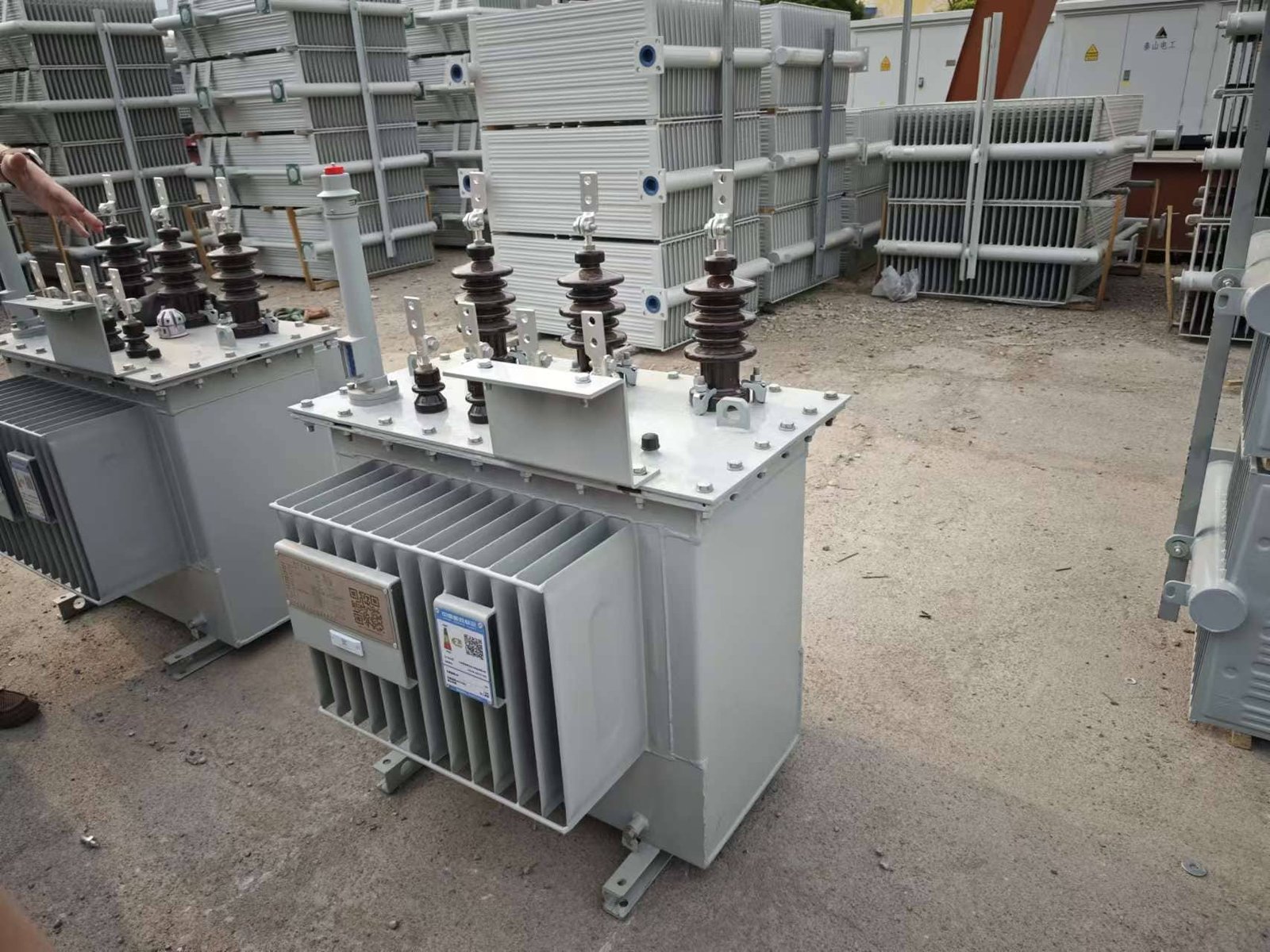
A distribution transformer is a transformer designed to step down medium-voltage electricity from distribution networks to lower utilization voltages suitable for homes, commercial buildings, and industrial facilities. Distribution transformers are commonly used in residential neighborhoods, commercial complexes, factories, schools, hospitals, renewable energy systems, and public infrastructure projects.
Because they operate close to end users and remain energized for long periods, distribution transformers are optimized for high efficiency, excellent voltage regulation, and long service life.
Distribution transformers are primarily used to increase voltage for long-distance power transmission.False
Distribution transformers are designed primarily to reduce medium-voltage electricity to lower voltages suitable for end-user consumption. Voltage step-up for transmission is performed by generator step-up transformers.
Understanding the Role of Distribution Transformers
The electrical power system consists of several stages.
Power Delivery Chain
| Stage | Typical Voltage |
|---|---|
| Generation | 11–25 kV |
| Transmission | 110–765 kV |
| Distribution | 4–35 kV |
| Utilization | 120–600 V |
Distribution transformers perform the final voltage conversion step.
Why Voltage Must Be Reduced
High-voltage transmission is efficient but unsuitable for direct use.
Reasons for Voltage Reduction
| Reason | Benefit |
|---|---|
| Equipment compatibility | Safe operation |
| Consumer safety | Reduced risk |
| Appliance requirements | Proper functionality |
Distribution transformers make electricity usable for customers.
What Is a Distribution Transformer?
A distribution transformer is a transformer specifically designed for local power distribution.
Main Characteristics
| Feature | Description |
|---|---|
| Continuous operation | 24/7 service |
| Voltage reduction | Medium to low voltage |
| High efficiency | Reduced losses |
| Customer proximity | Located near loads |
These characteristics distinguish them from transmission-level transformers.
How a Distribution Transformer Works
Distribution transformers operate according to electromagnetic induction.
Operating Principle
| Step | Process |
|---|---|
| Medium-voltage input received | Primary energized |
| Magnetic flux created | Core energized |
| Secondary voltage induced | Lower voltage produced |
| Power delivered to consumers | End-use supply |
The operating principle is identical to other transformer types.
Voltage Transformation Relationship
The output voltage depends on the winding turns ratio.
Transformer Voltage Ratio
\frac{V_p}{V_s}=\frac{N_p}{N_s}
Where:
- (V_p) = primary voltage
- (V_s) = secondary voltage
- (N_p) = primary turns
- (N_s) = secondary turns
This relationship determines the required voltage conversion.
Main Components of a Distribution Transformer
Several components work together to ensure reliable operation.
Core Components
| Component | Function |
|---|---|
| Magnetic core | Flux transfer |
| Primary winding | Receives input voltage |
| Secondary winding | Supplies output voltage |
| Insulation system | Electrical isolation |
| Tank or enclosure | Protection |
| Cooling system | Heat dissipation |
Each component influences transformer performance.
Common Voltage Ratings
Distribution transformers are available in numerous voltage combinations.
Typical Primary Voltages
| Voltage Level | Application |
|---|---|
| 4.16 kV | Local distribution |
| 11 kV | Urban networks |
| 13.8 kV | Utility systems |
| 22 kV | Regional distribution |
| 33 kV | Industrial distribution |
Primary voltage depends on local utility standards.
Typical Secondary Voltages
| Voltage | Common Use |
|---|---|
| 120/240 V | Residential |
| 208Y/120 V | Commercial |
| 400/230 V | International systems |
| 480Y/277 V | Industrial facilities |
Secondary voltages are selected according to customer requirements.
Types of Distribution Transformers
Distribution transformers can be classified by installation method.
Pole-Mounted Transformers
Pole-mounted units are common in overhead distribution systems.
Characteristics
| Feature | Benefit |
|---|---|
| Elevated installation | Reduced footprint |
| Lower infrastructure cost | Economic deployment |
| Easy utility access | Maintenance convenience |
These transformers are common in suburban and rural areas.
Pad-Mounted Transformers
Pad-mounted transformers are widely used in underground distribution systems.
Features
| Feature | Benefit |
|---|---|
| Ground-level installation | Accessibility |
| Tamper-resistant enclosure | Safety |
| Aesthetic appearance | Urban suitability |
They are common in residential developments and commercial complexes.
Dry-Type Distribution Transformers
Dry-type designs eliminate insulating oil.
Advantages
| Benefit | Result |
|---|---|
| Improved fire safety | Indoor suitability |
| No oil leakage | Environmental protection |
| Lower maintenance | Reduced operating costs |
These transformers are often installed inside buildings.
Oil-Filled Distribution Transformers
Oil-filled transformers remain widely used outdoors.
Advantages
| Benefit | Result |
|---|---|
| Excellent cooling | High efficiency |
| Proven technology | Long service history |
| Cost effectiveness | Broad adoption |
Utilities commonly deploy oil-filled designs.
Residential Applications
Residential power distribution represents one of the largest markets.
Typical Uses
| Application | Purpose |
|---|---|
| Single-family homes | Household power |
| Apartment complexes | Shared distribution |
| Residential communities | Neighborhood supply |
Distribution transformers provide electricity for daily living.
Commercial Applications
Commercial facilities require reliable voltage conversion.
Examples
| Facility | Transformer Function |
|---|---|
| Office buildings | Building distribution |
| Shopping centers | Retail power |
| Hotels | Facility operations |
| Restaurants | Equipment supply |
Commercial demand often varies throughout the day.
Industrial Applications
Industrial facilities frequently utilize dedicated distribution transformers.
Industrial Uses
| Industry | Application |
|---|---|
| Manufacturing | Process equipment |
| Mining | Site power |
| Food processing | Production systems |
| Chemical plants | Facility operations |
Industrial transformers often handle larger loads.
Healthcare Facilities
Hospitals require dependable electrical infrastructure.
Transformer Applications
| System | Purpose |
|---|---|
| Main distribution | Facility power |
| Emergency systems | Backup support |
| Medical equipment | Critical loads |
Reliability is particularly important in healthcare environments.
Educational Institutions
Schools and universities depend on local power distribution.
Common Applications
| Facility | Purpose |
|---|---|
| Schools | Classroom power |
| Universities | Campus distribution |
| Laboratories | Specialized equipment |
Distribution transformers support daily operations.
Renewable Energy Systems
Renewable energy facilities increasingly use distribution transformers.
Solar Power Applications
| Function | Purpose |
|---|---|
| Voltage conversion | Grid connection |
| Collection systems | Energy aggregation |
Distribution transformers help integrate renewable generation.
Wind Energy Applications
| Function | Purpose |
|---|---|
| Turbine output conversion | Voltage adaptation |
| Collection networks | Power transfer |
Wind farms rely on multiple transformer stages.
Public Infrastructure
Many public services depend on distribution transformers.
Infrastructure Examples
| Facility | Application |
|---|---|
| Airports | Facility power |
| Water treatment plants | Equipment supply |
| Transit systems | Distribution networks |
Reliable operation is essential.
Data Centers
Modern digital infrastructure requires stable power.
Transformer Roles
| Function | Purpose |
|---|---|
| Voltage reduction | Equipment supply |
| Isolation | Power quality |
| Reliability | Continuous operation |
Distribution transformers support critical IT systems.
Efficiency Requirements
Distribution transformers operate continuously and therefore prioritize efficiency.
Efficiency Formula
\eta=\frac{P{out}}{P{in}}\times100%
Typical Efficiency Levels
| Transformer Type | Efficiency |
|---|---|
| Standard distribution transformer | 97–99% |
| High-efficiency model | Above 99% |
Even small efficiency improvements can produce significant energy savings.
Voltage Regulation Performance
Good voltage regulation is essential for customer satisfaction.
Voltage Regulation Formula
%VR=\frac{V{NL}-V{FL}}{V_{FL}}\times100
Lower voltage regulation values generally indicate better performance.
Distribution Transformer Capacity Range
Distribution transformers are available in a wide range of ratings.
Typical Capacities
| Capacity Range | Common Application |
|---|---|
| 10–100 kVA | Small residential loads |
| 100–500 kVA | Commercial buildings |
| 500–2500 kVA | Industrial facilities |
| Above 2500 kVA | Large distribution networks |
Sizing depends on load demand and future growth.
Advantages of Distribution Transformers
| Advantage | Benefit |
|---|---|
| Reliable voltage conversion | Stable power supply |
| High efficiency | Reduced energy loss |
| Long service life | Lower lifecycle cost |
| Flexible installation | Broad application range |
| Scalable capacity | Adaptable design |
These benefits support modern electrical infrastructure.
Summary of Common Applications
| Sector | Typical Use |
|---|---|
| Residential | Household power |
| Commercial | Building distribution |
| Industrial | Equipment supply |
| Healthcare | Critical systems |
| Education | Campus power |
| Renewable energy | Grid integration |
| Public infrastructure | Utility services |
| Data centers | IT operations |
Distribution transformers serve virtually every sector of society.
What Is a Power Transformer and How Does It Differ from Other Types?
Electric power systems depend on transformers to efficiently transfer energy between different voltage levels. From generation plants to transmission networks and local distribution systems, transformers ensure that electricity can be transmitted economically and delivered safely to end users. Among the many transformer categories, the power transformer is one of the most critical components of the electrical grid, enabling large-scale energy transfer across high-voltage transmission networks.
Although power transformers share the same fundamental operating principle as distribution transformers, dry-type transformers, and isolation transformers, they are designed for different operating conditions and applications. Understanding these differences is essential when selecting transformers for utility, industrial, renewable energy, or infrastructure projects.
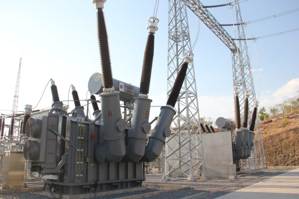
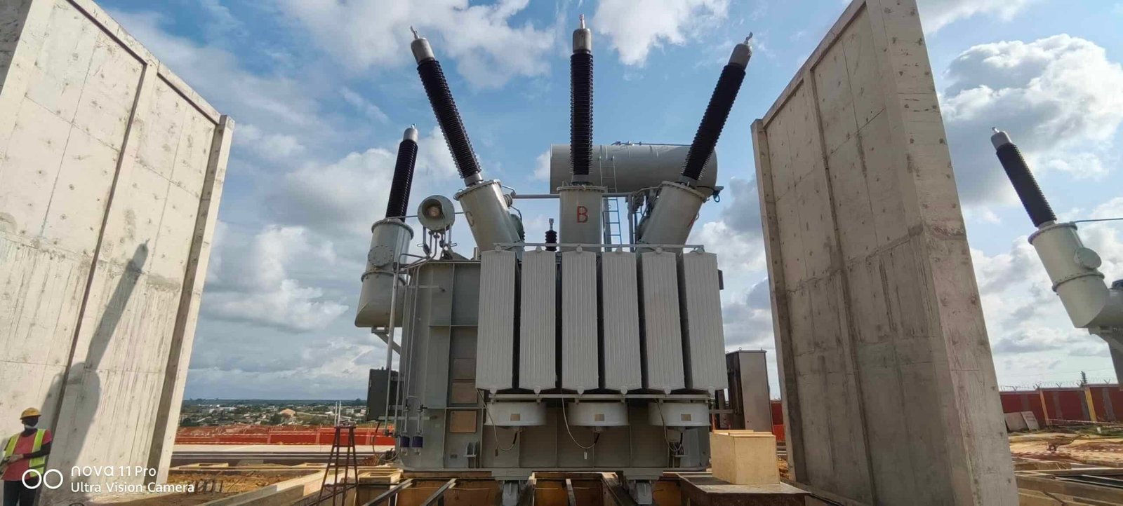
A power transformer is a high-capacity transformer primarily used in electrical generation plants, transmission substations, and high-voltage power networks to step up or step down voltage levels for bulk power transfer. Unlike distribution transformers, which serve end users, power transformers are designed for high-voltage operation, large power ratings, maximum efficiency near full load, and transmission-level applications.
As the backbone of modern power transmission systems, power transformers play a crucial role in ensuring reliable and efficient electricity delivery over long distances.
Power transformers are mainly used to supply electricity directly to residential homes and small commercial buildings.False
Power transformers are generally used in generation plants and transmission substations for bulk power transfer. Residential and commercial consumers are typically supplied through distribution transformers.
What Is a Power Transformer?
A power transformer is a transformer designed to transfer large amounts of electrical power between high-voltage networks.
Primary Purpose
The main objective is to enable efficient bulk power transmission.
Core Functions
| Function | Purpose |
|---|---|
| Voltage step-up | Transmission efficiency |
| Voltage step-down | Grid interconnection |
| Power transfer | Large-scale energy movement |
| Network isolation | System reliability |
Power transformers operate at the highest levels of the electrical grid.
Where Power Transformers Fit in the Electrical System
Electricity passes through multiple voltage conversion stages.
Typical Power Flow
| Stage | Voltage Range |
|---|---|
| Generation | 11–25 kV |
| Step-up transformer | 110–765 kV |
| Transmission network | 110–765 kV |
| Step-down transformer | 33–220 kV |
| Distribution network | 4–35 kV |
| End users | 120–600 V |
Power transformers primarily operate in the transmission stages.
How a Power Transformer Works
Like all transformers, power transformers operate through electromagnetic induction.
Operating Process
| Step | Description |
|---|---|
| AC voltage applied | Current flows |
| Magnetic flux generated | Core energized |
| Flux links secondary winding | Voltage induced |
| Energy transferred | Power delivered |
The operating principle remains identical regardless of transformer size.
Fundamental Voltage Relationship
Voltage transformation depends on winding turns ratio.
Transformer Equation
\frac{V_p}{V_s}=\frac{N_p}{N_s}
Where:
- (V_p) = primary voltage
- (V_s) = secondary voltage
- (N_p) = primary turns
- (N_s) = secondary turns
This relationship governs both step-up and step-down operation.
Key Characteristics of Power Transformers
Power transformers are designed differently from other transformer categories.
Main Characteristics
| Characteristic | Description |
|---|---|
| High voltage operation | Transmission-level voltages |
| Large power ratings | MVA capacity |
| High efficiency | Minimized losses |
| Continuous operation | Utility service |
| Substation installation | Grid infrastructure |
These features distinguish power transformers from lower-voltage designs.
Typical Power Transformer Ratings
Power transformers are available in a broad range of capacities.
Common Capacity Range
| Rating | Application |
|---|---|
| 5–50 MVA | Regional substations |
| 50–250 MVA | Transmission substations |
| 250–1000+ MVA | Major grid interconnections |
Large utility transformers may exceed several hundred MVA.
Typical Voltage Levels
High-Voltage Applications
| Voltage Class | Common Use |
|---|---|
| 69 kV | Sub-transmission |
| 115 kV | Regional transmission |
| 230 kV | Transmission |
| 345 kV | Bulk transmission |
| 500 kV | Long-distance transmission |
| 765 kV | Ultra-high voltage networks |
Voltage levels vary by country and utility requirements.
Power Transformer vs Distribution Transformer
The most common comparison is between power and distribution transformers.
Major Differences
| Feature | Power Transformer | Distribution Transformer |
|---|---|---|
| Primary application | Transmission | Local distribution |
| Voltage level | High voltage | Medium voltage |
| Capacity | High MVA | Lower kVA/MVA |
| Load profile | Near full load | Variable load |
| Installation location | Substations | Near consumers |
Both are essential but serve different purposes.
Efficiency Design Philosophy
Efficiency requirements differ significantly.
Operating Conditions
| Transformer Type | Optimized For |
|---|---|
| Power transformer | Full-load efficiency |
| Distribution transformer | All-day efficiency |
This difference reflects their operating environments.
Why Full-Load Efficiency Matters
Power transformers typically operate close to rated capacity.
Benefits
| Benefit | Impact |
|---|---|
| Lower losses | Energy savings |
| Reduced heating | Longer life |
| Improved grid efficiency | Economic operation |
Utilities prioritize efficiency due to large power transfers.
Power Transformer vs Dry-Type Transformer
Dry-type transformers and power transformers serve different markets.
Comparison
| Feature | Power Transformer | Dry-Type Transformer |
|---|---|---|
| Cooling medium | Oil | Air |
| Installation | Outdoor substations | Indoor facilities |
| Voltage range | Very high | Low to medium |
| Capacity | Very large | Small to medium |
Large transmission applications typically require oil-filled designs.
Power Transformer vs Isolation Transformer
Isolation transformers have a different primary purpose.
Key Difference
| Transformer Type | Primary Objective |
|---|---|
| Power transformer | Voltage conversion |
| Isolation transformer | Electrical isolation |
Isolation transformers often have a 1:1 turns ratio.
Step-Up Power Transformers
Generator step-up transformers are a major category.
Function
Power plants generate electricity at moderate voltages.
Typical Example
| Stage | Voltage |
|---|---|
| Generator output | 13.8 kV |
| Transformer output | 230–500 kV |
This enables efficient long-distance transmission.
Step-Down Power Transformers
Transmission substations use step-down power transformers.
Purpose
| Function | Benefit |
|---|---|
| Reduce transmission voltage | Distribution compatibility |
| Improve system integration | Grid flexibility |
Multiple voltage reduction stages often occur before electricity reaches consumers.
Main Components of a Power Transformer
Large power transformers contain several critical systems.
Major Components
| Component | Function |
|---|---|
| Magnetic core | Flux transfer |
| Windings | Energy conversion |
| Insulation system | Electrical isolation |
| Oil system | Cooling and insulation |
| Radiators | Heat dissipation |
| Tap changer | Voltage regulation |
Each component is designed for high-voltage operation.
Cooling Systems
Power transformers generate substantial heat.
Common Cooling Methods
| Cooling Class | Description |
|---|---|
| ONAN | Oil Natural Air Natural |
| ONAF | Oil Natural Air Forced |
| OFAF | Oil Forced Air Forced |
| OFWF | Oil Forced Water Forced |
Cooling capability directly affects transformer capacity.
Voltage Regulation Capabilities
Power transformers often include tap changers.
Purpose of Tap Changers
| Function | Benefit |
|---|---|
| Voltage adjustment | Stable system voltage |
| Compensation for load variation | Improved power quality |
This helps maintain grid performance.
Reliability Requirements
Power transformers are among the most critical grid assets.
Importance
| Factor | Significance |
|---|---|
| High capital cost | Major investment |
| Network dependence | Critical infrastructure |
| Long service life | 30–50+ years |
Reliability is therefore a primary design objective.
Applications of Power Transformers
Power transformers serve many utility-scale applications.
Common Uses
| Application | Purpose |
|---|---|
| Power plants | Generator step-up |
| Transmission substations | Voltage conversion |
| Renewable energy plants | Grid interconnection |
| Industrial utility systems | Bulk power transfer |
They form the backbone of large-scale electrical networks.
Renewable Energy Applications
Large renewable projects often require power transformers.
Examples
| Project Type | Transformer Function |
|---|---|
| Solar farms | Grid connection |
| Wind farms | Voltage step-up |
| Hydroelectric plants | Transmission integration |
Power transformers facilitate renewable energy delivery.
Efficiency of Power Transformers
Power transformers achieve extremely high efficiency.
Efficiency Formula
\eta=\frac{P{out}}{P{in}}\times100%
Typical Efficiency
| Transformer Size | Efficiency |
|---|---|
| Medium power transformer | 98–99% |
| Large power transformer | 99–99.75% |
Even small improvements can save substantial energy.
Comparison of Major Transformer Types
| Feature | Power Transformer | Distribution Transformer | Dry-Type Transformer | Isolation Transformer |
|---|---|---|---|---|
| Main purpose | Bulk power transfer | Local distribution | Safe indoor distribution | Electrical isolation |
| Voltage level | High | Medium/low | Low/medium | Variable |
| Capacity | Very high | Moderate | Moderate | Low/moderate |
| Installation | Substations | Near loads | Buildings | Equipment systems |
| Cooling | Usually oil | Oil or dry-type | Air | Various |
This comparison highlights their different roles.
Advantages of Power Transformers
| Advantage | Benefit |
|---|---|
| Efficient long-distance transmission | Reduced losses |
| High capacity | Bulk power handling |
| Excellent reliability | Grid stability |
| Voltage flexibility | System integration |
| Long service life | Asset value |
These advantages make power transformers indispensable.
What Is an Autotransformer and What Are Its Advantages?
Voltage transformation is a fundamental requirement in electrical power systems, industrial facilities, renewable energy projects, and motor control applications. While most people are familiar with conventional two-winding transformers that provide complete electrical isolation between primary and secondary circuits, another important transformer design—the autotransformer—offers a more compact, efficient, and economical solution for certain voltage conversion requirements.
Autotransformers are widely used where the voltage difference between input and output is relatively small. Because they utilize a single winding instead of separate primary and secondary windings, they can achieve higher efficiency, lower cost, reduced size, and improved voltage regulation compared to conventional transformers of the same rating. However, these advantages come with specific design considerations, particularly regarding electrical isolation and fault protection.
An autotransformer is a transformer that uses a single continuous winding with one or more taps to provide both primary and secondary voltages. Unlike conventional transformers that have separate primary and secondary windings, an autotransformer shares part of the same winding between the input and output circuits. Its main advantages include higher efficiency, lower cost, smaller size, reduced weight, improved voltage regulation, and lower material usage.
Because of these benefits, autotransformers are commonly used in power transmission systems, motor starting applications, voltage regulation equipment, and industrial electrical networks.
An autotransformer provides complete electrical isolation between the primary and secondary circuits, just like a conventional two-winding transformer.False
Because part of the winding is shared between the input and output circuits, autotransformers do not provide full galvanic isolation between primary and secondary sides.
What Is an Autotransformer?
An autotransformer is a transformer with a single winding that serves both the primary and secondary circuits.
Basic Structure
Unlike conventional transformers, which have separate windings, an autotransformer uses one continuous winding with taps.
Main Components
| Component | Function |
|---|---|
| Magnetic core | Flux transfer |
| Single winding | Input and output connection |
| Voltage taps | Voltage selection |
| Insulation system | Electrical protection |
This simplified construction contributes to its economic advantages.
How an Autotransformer Works
Autotransformers operate using electromagnetic induction and direct electrical connection.
Energy Transfer Mechanisms
| Mechanism | Description |
|---|---|
| Conductive transfer | Through shared winding |
| Inductive transfer | Through magnetic coupling |
Both methods contribute to power transfer simultaneously.
Basic Operating Principle
When AC voltage is applied to the winding, magnetic flux develops in the core.
Operating Sequence
| Step | Process |
|---|---|
| Input voltage applied | Current flows |
| Magnetic flux generated | Core energized |
| Voltage induced in winding | Output produced |
| Load connected | Power delivered |
The operation follows the same electromagnetic principles as other transformers.
Typical Autotransformer Configuration
The winding contains taps that provide different voltage levels.
Example
| Connection Point | Voltage |
|---|---|
| Full winding | 480 V |
| Intermediate tap | 240 V |
| Lower tap | 120 V |
Voltage depends on the number of turns between connection points.
Voltage Ratio Relationship
The output voltage depends on the winding turns ratio.
Transformer Equation
\frac{V_1}{V_2}=\frac{N_1}{N_2}
Where:
- (V_1) = primary voltage
- (V_2) = secondary voltage
- (N_1) = primary turns
- (N_2) = secondary turns
This relationship governs autotransformer voltage conversion.
Difference Between an Autotransformer and a Conventional Transformer
The primary distinction lies in winding construction.
Comparison
| Feature | Autotransformer | Conventional Transformer |
|---|---|---|
| Number of windings | One | Two |
| Electrical isolation | No | Yes |
| Material usage | Lower | Higher |
| Cost | Lower | Higher |
| Size | Smaller | Larger |
These differences influence application selection.
Why an Autotransformer Is More Efficient
A portion of power is transferred directly through the winding.
Energy Transfer Comparison
| Transformer Type | Transfer Method |
|---|---|
| Conventional transformer | Entirely inductive |
| Autotransformer | Inductive + conductive |
This reduces losses and improves efficiency.
Higher Efficiency
One of the most significant advantages is improved efficiency.
Efficiency Formula
\eta=\frac{P{out}}{P{in}}\times100%
Typical Efficiency Levels
| Transformer Type | Efficiency |
|---|---|
| Conventional transformer | 95–99% |
| Autotransformer | 98–99.8% |
Autotransformers often achieve exceptionally high efficiencies.
Reduced Copper Usage
A single winding requires less conductor material.
Material Savings
| Aspect | Benefit |
|---|---|
| Less copper | Lower cost |
| Smaller winding | Reduced weight |
| Lower resistance | Reduced losses |
Material savings can be substantial.
Smaller Physical Size
Autotransformers are generally more compact.
Comparison
| Characteristic | Advantage |
|---|---|
| Smaller core | Reduced footprint |
| Smaller winding | Compact design |
| Reduced weight | Easier installation |
This is especially valuable where space is limited.
Lower Manufacturing Cost
Reduced material requirements lower production costs.
Cost Benefits
| Factor | Effect |
|---|---|
| Less copper | Lower material cost |
| Smaller core | Reduced steel consumption |
| Simpler construction | Lower manufacturing expense |
Autotransformers are often the most economical option for suitable applications.
Better Voltage Regulation
Voltage regulation refers to voltage stability under changing loads.
Voltage Regulation Formula
%VR=\frac{V{NL}-V{FL}}{V_{FL}}\times100
Why Regulation Improves
| Reason | Benefit |
|---|---|
| Lower winding resistance | Reduced voltage drop |
| Lower leakage reactance | Better load performance |
Improved regulation enhances power quality.
Lower Losses
Autotransformers typically exhibit lower losses.
Types of Losses
| Loss Type | Effect |
|---|---|
| Copper loss | Reduced |
| Stray loss | Lower |
| Load loss | Lower overall |
Reduced losses improve operating efficiency.
Higher Capacity for Similar Size
Autotransformers can provide greater capacity than equivalent two-winding designs.
Benefits
| Feature | Advantage |
|---|---|
| More power handling | Higher utilization |
| Smaller footprint | Space savings |
| Lower cost per kVA | Economic benefit |
This makes them attractive for utility applications.
Main Limitation: Lack of Electrical Isolation
The most important disadvantage is the absence of galvanic isolation.
Why It Matters
| Issue | Consequence |
|---|---|
| Shared winding | Direct electrical connection |
| Fault propagation | Increased risk |
| Grounding concerns | System design challenges |
Isolation requirements must be carefully evaluated.
Short-Circuit Considerations
Autotransformers may experience higher fault currents.
Comparison
| Characteristic | Autotransformer | Conventional Transformer |
|---|---|---|
| Impedance | Lower | |
| Fault current | Higher | |
| Isolation | Lower |
Protection systems must be appropriately designed.
Common Applications of Autotransformers
Autotransformers are widely used where voltage ratios are relatively small.
Typical Uses
| Application | Purpose |
|---|---|
| Voltage conversion | Utility systems |
| Motor starting | Reduced inrush current |
| Voltage regulation | Power quality improvement |
| Grid interconnection | System compatibility |
These applications benefit from efficiency and economy.
Power Transmission Systems
Utilities frequently employ autotransformers.
Why Utilities Use Them
| Benefit | Impact |
|---|---|
| High efficiency | Reduced losses |
| Lower cost | Economic advantage |
| Large capacity | Bulk power transfer |
They are commonly used between transmission voltage levels.
Example Utility Applications
| Voltage Conversion | Application |
|---|---|
| 400 kV ↔ 220 kV | Transmission interconnection |
| 230 kV ↔ 138 kV | Regional networks |
| 138 kV ↔ 69 kV | Sub-transmission systems |
These are common utility configurations.
Motor Starting Applications
Large motors often utilize autotransformer starters.
Benefits
| Benefit | Result |
|---|---|
| Reduced starting current | Lower system stress |
| Reduced voltage dip | Improved stability |
| Smoother startup | Equipment protection |
This is common in industrial facilities.
Renewable Energy Systems
Some renewable projects employ autotransformers.
Applications
| Sector | Purpose |
|---|---|
| Wind farms | Voltage matching |
| Solar plants | Grid interconnection |
| Energy storage systems | Voltage adaptation |
Their efficiency supports renewable energy objectives.
Industrial Power Systems
Industrial facilities often require voltage conversion.
Common Uses
| Application | Purpose |
|---|---|
| Equipment compatibility | Voltage adjustment |
| Facility expansion | Network integration |
| Process systems | Reliable power delivery |
Autotransformers can offer cost-effective solutions.
Comparison of Transformer Types
| Feature | Autotransformer | Two-Winding Transformer |
|---|---|---|
| Electrical isolation | No | |
| Voltage transformation | Yes | |
| Efficiency | Higher | |
| Cost | Lower | |
| Weight | Lower | |
| Size | Smaller | |
| Safety isolation | Limited | |
| Fault current | Higher |
Each type has its own ideal applications.
Advantages Summary
| Advantage | Benefit |
|---|---|
| Higher efficiency | Lower operating costs |
| Smaller size | Easier installation |
| Reduced weight | Lower transportation cost |
| Less copper usage | Material savings |
| Better voltage regulation | Improved performance |
| Lower purchase cost | Economic benefit |
These factors explain the widespread use of autotransformers.
When Should an Autotransformer Be Used?
Autotransformers are generally preferred when:
| Condition | Suitability |
|---|---|
| Small voltage ratio | Excellent |
| Isolation not required | Excellent |
| High efficiency desired | Excellent |
| Space constraints exist | Excellent |
| Cost reduction important | Excellent |
Careful application analysis is essential.
What Is a Generator Step-Up (GSU) Transformer?
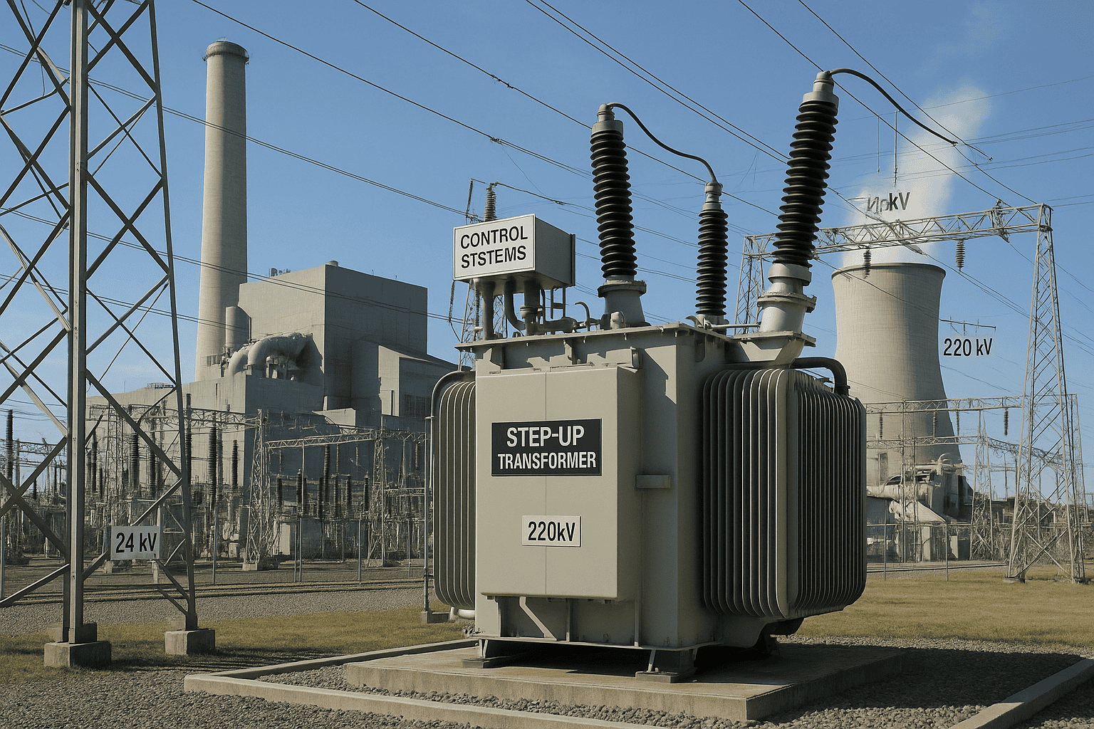
Electricity generated by power plants is typically produced at medium voltage levels, often ranging from 11 kV to 25 kV depending on the generator design. While these voltages are suitable for power generation equipment, they are not efficient for transmitting large amounts of electrical energy over long distances. To minimize transmission losses and improve grid efficiency, the generated voltage must be increased substantially before entering the transmission network. This critical task is performed by a Generator Step-Up (GSU) Transformer.
GSU transformers are among the most important assets in modern power generation facilities. Whether used in conventional thermal power stations, hydroelectric plants, nuclear facilities, solar farms, or wind power projects, they serve as the vital link between power generation equipment and the high-voltage transmission grid. Their reliability and efficiency directly influence the performance of the entire power generation system.
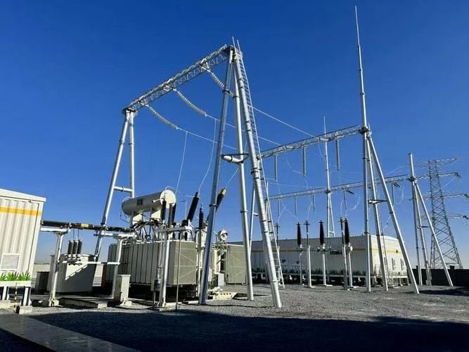
A Generator Step-Up (GSU) transformer is a power transformer installed between an electrical generator and the transmission network. Its primary function is to increase the generator's medium-voltage output to a much higher transmission voltage, enabling efficient long-distance power transfer with reduced current, lower losses, and improved grid performance.
Without GSU transformers, modern large-scale power generation and transmission systems would be significantly less efficient and far more costly to operate.
A Generator Step-Up transformer reduces generator voltage to levels suitable for residential consumers.False
A GSU transformer performs the opposite function. It increases generator voltage to high transmission levels so electricity can be transported efficiently across the power grid.
What Is a Generator Step-Up Transformer?
A Generator Step-Up transformer is a specialized high-capacity power transformer.
Primary Purpose
Its role is to connect generating units to transmission systems.
Main Functions
| Function | Purpose |
|---|---|
| Voltage step-up | Increase generator voltage |
| Grid connection | Interface with transmission system |
| Efficient power transfer | Reduce transmission losses |
| Electrical isolation | System protection |
GSU transformers are essential components of utility-scale generation facilities.
Why Voltage Must Be Increased
Generators typically produce electricity at medium voltages.
Typical Generator Voltages
| Generator Type | Common Output Voltage |
|---|---|
| Small generators | 4–15 kV |
| Utility generators | 11–25 kV |
| Large power plant generators | 13.8–24 kV |
These voltages are not ideal for long-distance transmission.
The Relationship Between Voltage and Current
For a given amount of power, increasing voltage reduces current.
Power Relationship
P=VI
Where:
- (P) = power
- (V) = voltage
- (I) = current
When voltage increases, current decreases for the same power transfer.
Why Lower Current Matters
Transmission losses are heavily influenced by current.
Copper Loss Equation
P_{loss}=I^2R
Where:
- (P_{loss}) = conductor losses
- (I) = current
- (R) = conductor resistance
Reducing current dramatically lowers transmission losses.
How a GSU Transformer Works
A GSU transformer operates according to electromagnetic induction.
Operating Process
| Step | Description |
|---|---|
| Generator supplies medium voltage | Primary winding energized |
| Magnetic flux develops | Core transfers energy |
| High voltage induced | Secondary winding output |
| Power delivered to transmission grid | Long-distance transfer begins |
The operating principle is identical to other power transformers.
Voltage Transformation Principle
The voltage ratio depends on the winding turns ratio.
Transformer Voltage Equation
\frac{V_p}{V_s}=\frac{N_p}{N_s}
Where:
- (V_p) = generator voltage
- (V_s) = transmission voltage
- (N_p) = primary turns
- (N_s) = secondary turns
GSU transformers are designed with more turns on the high-voltage winding to increase voltage.
Typical GSU Voltage Conversions
The exact voltage levels vary by project and utility requirements.
Common Examples
| Generator Voltage | Transmission Voltage |
|---|---|
| 13.8 kV | 115 kV |
| 13.8 kV | 230 kV |
| 18 kV | 345 kV |
| 20 kV | 400 kV |
| 24 kV | 500 kV |
These voltage increases significantly improve transmission efficiency.
Where GSU Transformers Are Installed
GSU transformers are typically located close to generating units.
Installation Location
| Equipment | Connection |
|---|---|
| Generator | Low-voltage side |
| GSU transformer | Voltage conversion |
| Transmission switchyard | High-voltage side |
This arrangement minimizes generator-side losses.
Main Components of a GSU Transformer
GSU transformers contain many of the same components found in other large power transformers.
Major Components
| Component | Function |
|---|---|
| Magnetic core | Flux transfer |
| Low-voltage winding | Generator connection |
| High-voltage winding | Grid connection |
| Insulation system | Electrical isolation |
| Transformer oil | Cooling and insulation |
| Radiators | Heat dissipation |
| Bushings | External connections |
| Monitoring systems | Condition assessment |
These components are engineered for high reliability and long service life.
Power Ratings of GSU Transformers
GSU transformers handle very large amounts of power.
Typical Capacity Range
| Rating | Application |
|---|---|
| 10–100 MVA | Small generation facilities |
| 100–500 MVA | Utility power plants |
| 500–1500+ MVA | Large generating stations |
Some of the world's largest GSU transformers exceed 1000 MVA.
Cooling Systems Used in GSU Transformers
Because of their large capacities, effective cooling is essential.
Common Cooling Classes
| Cooling Method | Description |
|---|---|
| ONAN | Oil Natural Air Natural |
| ONAF | Oil Natural Air Forced |
| OFAF | Oil Forced Air Forced |
| OFWF | Oil Forced Water Forced |
Cooling capability directly affects transformer loading.
Why GSU Transformers Are Critical
The economic operation of power plants depends heavily on efficient voltage conversion.
Benefits
| Benefit | Impact |
|---|---|
| Reduced transmission losses | Lower operating costs |
| Improved grid efficiency | Better energy delivery |
| Higher transmission capacity | More power transfer |
| Enhanced system reliability | Stable operation |
These benefits justify the significant investment in GSU equipment.
GSU Transformers in Conventional Power Plants
Traditional power stations rely heavily on GSU transformers.
Applications
| Plant Type | Function |
|---|---|
| Coal-fired plants | Voltage step-up |
| Natural gas plants | Grid connection |
| Nuclear stations | Transmission integration |
| Hydroelectric plants | Power export |
Every large generating facility requires voltage transformation.
GSU Transformers in Renewable Energy Projects
Renewable energy facilities also depend on GSU transformers.
Solar Power Plants
| Function | Purpose |
|---|---|
| Collector system integration | Power aggregation |
| Voltage step-up | Grid connection |
Utility-scale solar farms commonly use GSU transformers.
Wind Power Projects
| Function | Purpose |
|---|---|
| Wind farm collection | Power consolidation |
| Transmission interface | Voltage increase |
GSU transformers support efficient renewable energy transmission.
Hydroelectric Facilities
Hydropower stations often utilize large GSU transformers.
Typical Configuration
| Component | Voltage |
|---|---|
| Generator output | 13–18 kV |
| Transmission voltage | 115–500 kV |
The voltage increase enables regional power delivery.
Electrical Isolation Benefits
In addition to voltage conversion, GSU transformers provide electrical isolation.
Advantages
| Benefit | Purpose |
|---|---|
| Fault isolation | Equipment protection |
| Grounding flexibility | System design |
| Improved reliability | Stable operation |
Isolation contributes to overall grid security.
Efficiency of GSU Transformers
GSU transformers are among the most efficient electrical devices.
Efficiency Formula
\eta=\frac{P{out}}{P{in}}\times100%
Typical Efficiency
| Transformer Size | Efficiency |
|---|---|
| Medium GSU | 98.5–99.5% |
| Large utility GSU | Above 99.5% |
Even small efficiency improvements can save substantial energy.
Reliability Requirements
GSU transformers are critical power system assets.
Design Priorities
| Requirement | Importance |
|---|---|
| High reliability | Essential |
| Long service life | Essential |
| Thermal performance | High |
| Fault tolerance | High |
Unexpected outages can affect large portions of the grid.
Monitoring and Protection Systems
Modern GSU transformers include advanced monitoring technologies.
Common Monitoring Parameters
| Parameter | Purpose |
|---|---|
| Oil temperature | Thermal protection |
| Winding temperature | Overload protection |
| Dissolved gas analysis | Fault detection |
| Load current | Capacity management |
These systems improve reliability and maintenance planning.
GSU Transformer vs Distribution Transformer
| Feature | GSU Transformer | Distribution Transformer |
|---|---|---|
| Main purpose | Voltage step-up | Voltage step-down |
| Application | Generation facilities | End-user supply |
| Voltage level | High transmission voltage | Medium-to-low voltage |
| Capacity | Very high MVA | Lower kVA/MVA |
| Location | Power plants | Near consumers |
The two transformer types serve entirely different roles.
Advantages of GSU Transformers
| Advantage | Benefit |
|---|---|
| Efficient power transmission | Reduced losses |
| Increased voltage | Lower current |
| High capacity | Large-scale power transfer |
| Electrical isolation | Enhanced protection |
| Long service life | Improved asset value |
These characteristics make GSU transformers indispensable in modern power systems.
Summary of GSU Transformer Functions
| Function | Contribution |
|---|---|
| Voltage step-up | Transmission efficiency |
| Power transfer | Grid integration |
| Electrical isolation | System protection |
| Loss reduction | Improved economics |
| Reliability enhancement | Stable operation |
GSU transformers are fundamental to large-scale electricity generation.
What Are Instrument Transformers and Why Are They Important?
Modern electrical power systems often operate at voltages and currents far beyond the safe operating limits of meters, protection relays, monitoring devices, and control equipment. Directly connecting measurement instruments to high-voltage transmission lines or high-current circuits would be dangerous, impractical, and costly. To solve this challenge, power systems rely on specialized devices known as instrument transformers.
Instrument transformers provide accurate, scaled-down representations of system voltage and current while electrically isolating measuring and protection equipment from high-energy power circuits. They play a critical role in power system monitoring, revenue metering, fault detection, relay protection, automation, and grid management. Without instrument transformers, modern electrical networks could not safely perform accurate measurement and protection functions.
Instrument transformers are specialized transformers designed to reduce high voltages or high currents to standardized, measurable values for meters, relays, monitoring devices, and control systems. Their importance lies in providing electrical isolation, improving personnel safety, enabling accurate measurements, supporting protective relays, and ensuring reliable operation of electrical power systems.
Because they serve as the eyes and ears of the power system, instrument transformers are essential for both operational efficiency and system protection.
Instrument transformers are primarily used to transfer large amounts of electrical power to consumers.False
Instrument transformers are designed for measurement, monitoring, and protection purposes. They provide scaled representations of voltage and current rather than bulk power transfer.
What Is an Instrument Transformer?
An instrument transformer is a transformer designed specifically for measurement and protection applications.
Primary Functions
| Function | Purpose |
|---|---|
| Current measurement | Monitoring system current |
| Voltage measurement | Monitoring system voltage |
| Relay protection | Fault detection |
| Electrical isolation | Equipment and personnel safety |
Unlike power transformers, instrument transformers handle very small power levels.
Why Instrument Transformers Are Needed
Power systems often operate at extremely high voltages and currents.
Typical System Values
| System Type | Voltage Range |
|---|---|
| Distribution systems | 4–35 kV |
| Transmission systems | 69–765 kV |
| Industrial systems | Hundreds to thousands of amperes |
Most measuring devices cannot directly withstand these levels.
Problems Without Instrument Transformers
| Challenge | Consequence |
|---|---|
| Excessive voltage | Equipment damage |
| High current | Meter failure |
| Safety hazards | Personnel risk |
| Lack of isolation | Protection problems |
Instrument transformers solve these issues efficiently.
Main Types of Instrument Transformers
Instrument transformers are generally divided into two categories.
Primary Types
| Type | Function |
|---|---|
| Current Transformer (CT) | Current measurement |
| Voltage Transformer (VT/PT) | Voltage measurement |
Each type performs a specific measurement role.
What Is a Current Transformer (CT)?
A Current Transformer reduces large primary currents to standardized secondary currents.
Typical CT Output Ratings
| Standard Secondary Current | Common Use |
|---|---|
| 1 A | Modern protection systems |
| 5 A | Traditional metering and relays |
The output remains proportional to the primary current.
How a Current Transformer Works
The primary conductor acts as the primary winding.
Operating Process
| Step | Description |
|---|---|
| Primary current flows | Magnetic field generated |
| Core transfers magnetic flux | Induction occurs |
| Secondary current produced | Scaled measurement output |
The CT reproduces current proportionally.
Current Transformation Ratio
The current ratio depends on the turns ratio.
CT Relationship
\frac{I_p}{I_s}=\frac{N_s}{N_p}
Where:
- (I_p) = primary current
- (I_s) = secondary current
- (N_p) = primary turns
- (N_s) = secondary turns
This relationship allows accurate current scaling.
Example CT Ratios
| Primary Current | Secondary Current |
|---|---|
| 100 A | 5 A |
| 400 A | 5 A |
| 1000 A | 5 A |
| 2000 A | 1 A |
These ratios are common in power systems.
What Is a Voltage Transformer (VT/PT)?
A Voltage Transformer, also called a Potential Transformer (PT), reduces high voltages to standardized levels.
Typical Secondary Voltages
| Output Voltage | Application |
|---|---|
| 110 V | Protection systems |
| 120 V | Metering systems |
| 100 V | International applications |
The reduced voltage remains proportional to the primary voltage.
How a Voltage Transformer Works
Voltage transformers operate similarly to conventional transformers.
Operating Principle
| Step | Description |
|---|---|
| Primary voltage applied | Magnetic flux generated |
| Flux links secondary winding | Voltage induced |
| Reduced voltage output | Measurement and protection |
This provides a safe measurement signal.
Voltage Transformation Relationship
Voltage Ratio Formula
\frac{V_p}{V_s}=\frac{N_p}{N_s}
Where:
- (V_p) = primary voltage
- (V_s) = secondary voltage
- (N_p) = primary turns
- (N_s) = secondary turns
The winding ratio determines the output voltage.
Current Transformers vs Voltage Transformers
| Characteristic | Current Transformer | Voltage Transformer |
|---|---|---|
| Measures | Current | Voltage |
| Connected | Series | Parallel |
| Secondary output | 1 A or 5 A | 100–120 V |
| Application | Current monitoring | Voltage monitoring |
Both types often operate together.
Importance of Electrical Isolation
One of the most important functions is electrical isolation.
Benefits
| Benefit | Importance |
|---|---|
| Personnel safety | Very high |
| Equipment protection | Very high |
| Reduced fault exposure | High |
| Improved reliability | High |
Isolation protects sensitive devices from dangerous system voltages.
Importance in Metering
Accurate energy measurement depends on instrument transformers.
Metering Applications
| Application | Purpose |
|---|---|
| Utility billing | Revenue metering |
| Industrial monitoring | Energy management |
| Load analysis | System optimization |
Measurement accuracy directly affects operational decisions.
Revenue Metering Applications
Utilities rely on instrument transformers for billing accuracy.
Typical Uses
| Customer Type | Application |
|---|---|
| Industrial facilities | Energy billing |
| Commercial buildings | Consumption monitoring |
| Power plants | Generation measurement |
Accurate measurement has significant financial implications.
Importance in Protective Relaying
Protective relays require accurate current and voltage information.
Protection Functions
| Protection Type | Purpose |
|---|---|
| Overcurrent protection | Fault detection |
| Differential protection | Equipment protection |
| Distance protection | Transmission line protection |
| Ground fault protection | Safety enhancement |
Instrument transformers provide the necessary inputs.
Fault Detection
Instrument transformers help detect abnormal conditions.
Examples
| Condition | Detection Method |
|---|---|
| Short circuit | Current increase |
| Overvoltage | Voltage increase |
| Ground fault | Current imbalance |
Protection systems respond rapidly to these events.
Importance in Grid Stability
Modern power systems depend on continuous monitoring.
Monitoring Functions
| Function | Benefit |
|---|---|
| Load measurement | Capacity management |
| Voltage monitoring | Power quality |
| Frequency analysis | Grid stability |
Instrument transformers provide essential operating data.
Automation and Smart Grids
Modern substations increasingly rely on digital systems.
Applications
| System | Purpose |
|---|---|
| SCADA | Remote monitoring |
| Digital relays | Protection |
| Smart metering | Data collection |
| Grid automation | Operational efficiency |
Instrument transformers provide critical measurement inputs.
Types of Current Transformers
Several CT designs exist.
Common CT Types
| Type | Application |
|---|---|
| Wound CT | Precision metering |
| Bar-type CT | High-current systems |
| Window CT | Switchgear installations |
| Bushing CT | Power transformers |
Selection depends on the application.
Types of Voltage Transformers
Voltage transformers also have several configurations.
Common VT Types
| Type | Application |
|---|---|
| Electromagnetic VT | Standard substations |
| Capacitive VT (CVT) | High-voltage transmission |
| Indoor VT | Industrial facilities |
| Outdoor VT | Utility substations |
Each design offers specific advantages.
Accuracy Requirements
Measurement accuracy is a critical parameter.
Accuracy Classes
| Application | Typical Requirement |
|---|---|
| Revenue metering | Very high accuracy |
| Protection systems | Reliable fault response |
| Monitoring | Moderate accuracy |
Transformer selection depends on accuracy needs.
Instrument Transformer Burden
The burden refers to the load connected to the secondary circuit.
Why Burden Matters
| Effect | Impact |
|---|---|
| Excessive burden | Reduced accuracy |
| Proper burden | Accurate measurements |
| Low burden | Improved performance |
Manufacturers specify allowable burden ratings.
Safety Considerations
Instrument transformers improve overall electrical safety.
Safety Benefits
| Feature | Benefit |
|---|---|
| Voltage reduction | Safer measurement |
| Current reduction | Equipment protection |
| Isolation | Personnel protection |
Safety is one of their primary purposes.
Common Installation Locations
Instrument transformers are used throughout power systems.
Typical Locations
| Facility | Application |
|---|---|
| Substations | Protection and metering |
| Power plants | Generator monitoring |
| Industrial facilities | Power management |
| Renewable energy plants | Grid integration |
Virtually every medium- and high-voltage installation uses them.
Applications in Renewable Energy Systems
Renewable facilities require extensive monitoring.
Common Uses
| Facility | Purpose |
|---|---|
| Solar farms | Revenue metering |
| Wind farms | Protection systems |
| Battery storage plants | Monitoring and control |
Instrument transformers support reliable renewable integration.
Comparison Between Power and Instrument Transformers
| Feature | Power Transformer | Instrument Transformer |
|---|---|---|
| Main purpose | Power transfer | Measurement and protection |
| Power handling | High | Very low |
| Output | Operational power | Measurement signals |
| Installation | Transmission/distribution systems | Monitoring circuits |
| Users | Loads and networks | Meters and relays |
Their functions are fundamentally different.
Advantages of Instrument Transformers
| Advantage | Benefit |
|---|---|
| Electrical isolation | Enhanced safety |
| Accurate measurements | Better decision-making |
| Protection support | Improved reliability |
| Standardized outputs | Equipment compatibility |
| Reduced equipment costs | Economic operation |
These benefits make them indispensable in power systems.
What Specialized Transformer Types Are Used in Modern Power Systems?
As electrical grids become more complex and interconnected, the demand for specialized transformer technologies continues to grow. While conventional power and distribution transformers remain the foundation of electricity transmission and distribution, many modern applications require transformers designed for highly specific operating conditions. Renewable energy integration, smart grids, industrial processing, HVDC transmission, power quality management, and advanced protection systems all rely on specialized transformer designs that perform functions beyond simple voltage conversion.
These transformers are engineered to address unique challenges such as harmonic distortion, power flow control, high fault currents, variable renewable generation, precision measurement, and extreme industrial loads. By performing specialized tasks, they enhance grid stability, efficiency, reliability, and operational flexibility across modern power systems.
Modern power systems use a variety of specialized transformer types, including Generator Step-Up (GSU) transformers, autotransformers, phase-shifting transformers, instrument transformers, converter transformers, rectifier transformers, furnace transformers, grounding transformers, renewable energy transformers, and smart transformers. Each type is designed to perform specific functions that improve power transmission, distribution, control, protection, and system reliability.
As power networks evolve toward greater digitalization and renewable energy integration, the importance of specialized transformers continues to increase.
All transformers used in modern power systems perform exactly the same functions and differ only in size.False
Many specialized transformer types are designed for unique applications such as power flow control, renewable energy integration, harmonic mitigation, HVDC conversion, industrial processing, grounding, measurement, and system protection.
Why Specialized Transformers Are Needed
Modern electrical systems face increasingly complex operational requirements.
Key Challenges
| Challenge | Impact |
|---|---|
| Renewable energy integration | Variable power flow |
| Growing electricity demand | Capacity expansion |
| Power quality requirements | Harmonic management |
| Grid interconnection | Voltage compatibility |
| Smart grid development | Advanced control |
Specialized transformers help address these challenges.
Classification of Specialized Transformers
Transformer designs vary according to application.
Major Categories
| Category | Primary Function |
|---|---|
| Generation transformers | Grid connection |
| Transmission transformers | Voltage control |
| Industrial transformers | Process support |
| Protection transformers | Measurement and safety |
| Renewable energy transformers | Energy integration |
Each category serves a distinct role within the power system.
Generator Step-Up (GSU) Transformers
GSU transformers connect generators to transmission networks.
Main Function
Electricity generated at medium voltage is stepped up to transmission voltage.
Typical Voltage Conversion
| Generator Voltage | Transmission Voltage |
|---|---|
| 13.8 kV | 115 kV |
| 15 kV | 230 kV |
| 20 kV | 400 kV |
| 24 kV | 500 kV |
GSU transformers are essential in power plants and renewable energy facilities.
Key Advantages
| Benefit | Result |
|---|---|
| Reduced transmission losses | Improved efficiency |
| Lower current | Higher transmission capacity |
| Grid compatibility | Reliable power export |
Autotransformers
Autotransformers use a single winding with multiple taps.
Main Characteristics
| Feature | Advantage |
|---|---|
| Single winding | Reduced material cost |
| Compact size | Space savings |
| High efficiency | Lower losses |
Autotransformers are commonly used when voltage ratios are relatively small.
Typical Applications
| Application | Purpose |
|---|---|
| Transmission interconnection | Voltage matching |
| Industrial systems | Voltage conversion |
| Motor starting | Reduced inrush current |
Phase-Shifting Transformers (PSTs)
Phase-shifting transformers control real power flow in transmission networks.
Operating Principle
By introducing a controlled phase-angle shift, power flow can be redirected.
Power Flow Relationship
P=\frac{V_1V_2}{X}\sin\delta
Where:
- (P) = transmitted power
- (V_1, V_2) = system voltages
- (X) = line reactance
- (\delta) = phase angle difference
Adjusting the phase angle changes power flow.
Benefits of PSTs
| Benefit | Impact |
|---|---|
| Congestion management | Improved network utilization |
| Power flow control | Enhanced stability |
| Interconnection support | Better system coordination |
Instrument Transformers
Instrument transformers provide scaled measurement signals.
Main Types
| Type | Function |
|---|---|
| Current Transformer (CT) | Current measurement |
| Voltage Transformer (VT/PT) | Voltage measurement |
They are critical for metering and protection.
Importance
| Application | Purpose |
|---|---|
| Revenue metering | Accurate billing |
| Protective relays | Fault detection |
| Monitoring systems | Grid management |
Converter Transformers
Converter transformers are used in HVDC systems.
Main Purpose
They connect AC networks to power electronic converters.
Applications
| Application | Function |
|---|---|
| HVDC transmission | AC/DC conversion |
| Interconnection projects | Power exchange |
| Offshore wind farms | Long-distance transmission |
Converter transformers are among the most technically demanding transformer designs.
Advantages
| Benefit | Result |
|---|---|
| Long-distance transmission | Lower losses |
| Grid interconnection | Enhanced flexibility |
| Renewable integration | Improved efficiency |
Rectifier Transformers
Rectifier transformers supply power conversion equipment.
Typical Applications
| Industry | Use |
|---|---|
| Aluminum production | Electrolysis |
| Steel manufacturing | DC process power |
| Chemical processing | Rectifier systems |
They are specifically designed to handle harmonic-rich loads.
Design Features
| Feature | Purpose |
|---|---|
| Harmonic tolerance | Improved reliability |
| Multiple secondary windings | Rectifier support |
| Enhanced thermal design | Heat management |
Furnace Transformers
Furnace transformers serve electric arc furnaces and similar equipment.
Key Characteristics
| Feature | Benefit |
|---|---|
| Extremely high current capability | Process support |
| Robust mechanical design | Fault resistance |
| Variable voltage operation | Process control |
These transformers operate under severe electrical conditions.
Common Applications
| Industry | Equipment |
|---|---|
| Steel production | Arc furnaces |
| Metallurgy | Smelting operations |
Grounding Transformers
Grounding transformers provide neutral points in power systems.
Main Functions
| Function | Benefit |
|---|---|
| Neutral creation | Grounding support |
| Fault current path | Protection operation |
| System stability | Improved reliability |
They are commonly used in delta-connected networks.
Zig-Zag Grounding Transformers
A popular grounding transformer design is the zig-zag transformer.
Advantages
| Benefit | Purpose |
|---|---|
| Effective grounding | System protection |
| Compact design | Reduced footprint |
| Fault current management | Safety enhancement |
Renewable Energy Transformers
Renewable energy systems often require specialized transformers.
Solar Power Transformers
| Function | Purpose |
|---|---|
| Inverter integration | Voltage conversion |
| Grid connection | Power export |
Solar projects use dedicated transformer solutions.
Wind Power Transformers
| Function | Purpose |
|---|---|
| Turbine output conversion | Voltage adaptation |
| Collection system support | Energy aggregation |
Wind farms may use hundreds of transformers.
Offshore Wind Transformers
Offshore installations present additional challenges.
Design Requirements
| Requirement | Importance |
|---|---|
| Corrosion resistance | High |
| Compact design | High |
| Reliability | Critical |
Offshore transformers operate in harsh marine environments.
Traction Transformers
Traction transformers are used in railway and transit systems.
Applications
| Sector | Use |
|---|---|
| High-speed rail | Power supply |
| Metro systems | Traction power |
| Electric locomotives | Voltage conversion |
Transportation electrification depends on these transformers.
Smart Transformers
Smart transformers represent an emerging technology.
Core Capabilities
| Feature | Benefit |
|---|---|
| Digital monitoring | Real-time diagnostics |
| Automated control | Enhanced performance |
| Communication systems | Smart grid integration |
These transformers support future grid development.
Benefits of Smart Transformers
| Benefit | Impact |
|---|---|
| Improved reliability | Reduced outages |
| Predictive maintenance | Lower costs |
| Renewable integration | Better flexibility |
Smart transformers are becoming increasingly important.
Harmonic Mitigation Transformers
Certain transformers are designed specifically to address harmonics.
Common Types
| Transformer Type | Purpose |
|---|---|
| K-rated transformer | Nonlinear loads |
| Harmonic mitigating transformer | Distortion reduction |
These designs improve power quality.
Isolation Transformers
Isolation transformers provide galvanic separation.
Benefits
| Benefit | Purpose |
|---|---|
| Electrical safety | Personnel protection |
| Noise reduction | Improved signal quality |
| Ground loop prevention | Reliable operation |
Isolation is important in many critical systems.
Mobile Substation Transformers
Temporary and emergency installations often use mobile transformers.
Applications
| Situation | Purpose |
|---|---|
| Disaster recovery | Rapid restoration |
| Maintenance projects | Temporary supply |
| Capacity upgrades | Transitional support |
Mobility enhances operational flexibility.
Comparison of Specialized Transformer Types
| Transformer Type | Primary Function | Typical Application |
|---|---|---|
| GSU Transformer | Voltage step-up | Power plants |
| Autotransformer | Efficient voltage conversion | Transmission systems |
| Phase-Shifting Transformer | Power flow control | Grid management |
| Instrument Transformer | Measurement | Protection and metering |
| Converter Transformer | AC/DC conversion | HVDC systems |
| Rectifier Transformer | Rectifier supply | Industrial processing |
| Furnace Transformer | High-current supply | Steel manufacturing |
| Grounding Transformer | Neutral grounding | Protection systems |
| Renewable Energy Transformer | Grid integration | Solar and wind projects |
| Smart Transformer | Digital control | Smart grids |
| Traction Transformer | Railway power | Transportation |
Each design addresses a unique operational requirement.
How Specialized Transformers Support Modern Power Systems
| Objective | Transformer Contribution |
|---|---|
| Grid stability | Power flow control |
| Renewable integration | Voltage adaptation |
| Protection | Accurate measurement |
| Industrial productivity | Process power supply |
| Smart grid operation | Digital monitoring |
| Efficient transmission | Voltage optimization |
These capabilities are essential for modern energy infrastructure.
Future Trends
Transformer technology continues to evolve.
Emerging Developments
| Trend | Impact |
|---|---|
| Digitalization | Smarter operation |
| Renewable expansion | New transformer designs |
| HVDC growth | Converter transformer demand |
| Grid automation | Advanced monitoring |
Specialized transformers will play an increasingly important role in future power systems.
Conclusion
Power transformers are available in several types, each designed for a specific role within electrical networks. Distribution transformers supply power to end users, power transformers support high-voltage transmission systems, autotransformers provide efficient voltage adjustment, and GSU transformers connect generators to transmission grids. In addition, instrument transformers and other specialized designs serve critical measurement, protection, and industrial functions. Selecting the appropriate transformer type depends on voltage requirements, capacity needs, system configuration, and application objectives.
FAQ
Q1: What are the main types of power transformers?
Power transformers can be classified according to their function, application, voltage level, insulation method, and construction design. The most common types include:
Distribution transformers
Power transformers
Autotransformers
Instrument transformers
Isolation transformers
Dry-type transformers
Oil-immersed transformers
Phase-shifting transformers
Each type is designed to meet specific electrical system requirements.
Q2: What is a distribution transformer?
A distribution transformer is used to reduce medium-voltage electricity from distribution networks to lower voltages suitable for homes, offices, and commercial facilities.
Key Characteristics:
Typically operates below 33 kV
Designed for continuous operation
Optimized for high efficiency at varying loads
Installed on poles, pads, or in substations
Common Applications:
Residential neighborhoods
Commercial buildings
Small industrial facilities
Distribution transformers are the final voltage-conversion stage before electricity reaches end users.
Q3: What is a power transformer?
A power transformer is used in high-voltage transmission systems to transfer large amounts of electrical energy between generation stations and substations.
Key Characteristics:
High voltage ratings
Large power capacities (MVA range)
Maximum efficiency near full load
Used in transmission networks
Common Applications:
Power plants
Transmission substations
Utility grids
Large industrial complexes
Power transformers are critical components of national electrical infrastructure.
Q4: What is an autotransformer?
An autotransformer uses a single continuous winding that serves as both the primary and secondary winding.
Advantages:
Smaller size
Lower cost
Higher efficiency
Reduced copper usage
Disadvantages:
No galvanic isolation between circuits
Lower fault isolation capability
Common Applications:
Voltage regulation
Motor starting systems
Interconnection of similar voltage networks
Industrial power systems
Autotransformers are often used when voltage differences are relatively small.
Q5: What are instrument transformers?
Instrument transformers are designed for measurement and protection purposes rather than power transfer.
They include:
Current Transformers (CTs)
Reduce high currents to measurable levels
Supply meters and protective relays
Voltage Transformers (VTs) or Potential Transformers (PTs)
Reduce high voltages for monitoring and protection systems
Common Applications:
Electrical substations
Metering systems
Protective relay circuits
Instrument transformers improve safety and measurement accuracy.
Q6: What is an isolation transformer?
An isolation transformer transfers power between circuits while providing complete electrical separation.
Benefits:
Enhanced personnel safety
Reduced electrical noise
Protection against ground faults
Improved equipment protection
Common Applications:
Medical facilities
Laboratories
Data centers
Sensitive electronic equipment
The primary and secondary windings are electrically isolated while remaining magnetically coupled.
Q7: How are transformers classified by insulation and cooling method?
Oil-Immersed Transformers
Use insulating oil for cooling and insulation
Suitable for large capacities
Excellent heat dissipation
Dry-Type Transformers
Use air and solid insulation materials
No oil leakage risk
Preferred for indoor installations
The choice depends on safety requirements, environmental conditions, and power rating.
Q8: What are some specialized transformer types?
Modern power systems also use specialized transformers such as:
Phase-Shifting Transformers
Control power flow in transmission networks
Rectifier Transformers
Supply DC conversion systems
Furnace Transformers
Power electric arc furnaces
Renewable Energy Transformers
Connect solar and wind farms to the grid
HVDC Converter Transformers
Support high-voltage direct current transmission systems
These transformers are engineered for specific operational demands and industries.
References
IEC 60076 – Power Transformers
https://webstore.iec.ch/publication/602
IEC 60076-11 – Dry-Type Transformers
https://webstore.iec.ch/publication/627
IEEE C57 Series – Transformer Standards
https://standards.ieee.org
Electrical Engineering Portal – Types of Transformers Explained
https://electrical-engineering-portal.com
National Electrical Manufacturers Association (NEMA) – Transformer Standards
https://www.nema.org
IEEE Power & Energy Society – Transformer Engineering Resources
https://ieeexplore.ieee.org