Proper installation and commissioning are critical to ensuring the safe, reliable, and efficient operation of transformers throughout their service life. Even a well-designed and thoroughly tested transformer can experience performance issues if installation procedures are not followed correctly. Adhering to industry best practices helps minimize risks, verify equipment readiness, and ensure successful integration into the power system.
What Site Preparation and Pre-Installation Checks Should Be Completed?
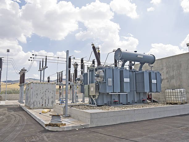
The successful installation of an oil-immersed transformer begins long before the unit arrives on site. Even a transformer that has been properly designed, manufactured, and factory-tested can experience operational problems if the installation site is inadequately prepared or if critical pre-installation inspections are overlooked. Site preparation and pre-installation verification are essential for ensuring safety, preventing equipment damage, reducing commissioning delays, and maximizing long-term reliability.
Transformer installation projects often involve substantial investments, and correcting site deficiencies after delivery can be costly and time-consuming. Therefore, utilities, industrial facilities, EPC contractors, and project owners should establish a comprehensive checklist covering civil works, environmental conditions, transportation access, grounding systems, safety provisions, and equipment inspections before installation begins.
Before installing an oil-immersed transformer, the site should be prepared with suitable foundations, grounding systems, oil containment measures, clearances, access routes, and safety infrastructure. Pre-installation checks should verify transportation condition, documentation, accessories, insulation condition, oil quality, and compliance with design specifications to ensure safe and reliable commissioning.
If a transformer passes factory acceptance testing, site preparation and pre-installation inspections are unnecessary.False
Factory testing verifies manufacturing quality, but site preparation and pre-installation inspections are essential to identify transportation damage, installation issues, environmental concerns, and site-specific compliance requirements.
Why Site Preparation Is Critical
Transformer installation environments can significantly affect operational reliability.
Proper preparation helps prevent:
| Risk | Potential Consequence |
|---|---|
| Foundation problems | Mechanical stress and vibration |
| Inadequate grounding | Safety hazards |
| Poor drainage | Corrosion and environmental damage |
| Restricted access | Maintenance difficulties |
| Improper clearances | Safety and operational risks |
Correcting these issues before installation is far less expensive than addressing them later.
Review of Project Documentation
Before any physical work begins, all project documentation should be reviewed.
Documents to verify
| Document | Purpose |
|---|---|
| Approved drawings | Confirm installation requirements |
| Transformer datasheets | Verify ratings and specifications |
| General arrangement drawings | Confirm dimensions and clearances |
| Foundation drawings | Validate civil works |
| Protection and control diagrams | Ensure system compatibility |
Documentation review helps prevent installation errors and specification mismatches.
Foundation Inspection
The transformer foundation must be capable of supporting the equipment safely throughout its service life.
Foundation verification checklist
| Item | Requirement |
|---|---|
| Dimensions | Match approved drawings |
| Elevation | Correct site level |
| Structural strength | Adequate load capacity |
| Surface levelness | Within specified tolerance |
Uneven foundations can introduce unwanted mechanical stresses.
Load-Bearing Capacity Verification
Transformers can weigh several tons to several hundred tons depending on size.
Factors to evaluate
| Parameter | Importance |
|---|---|
| Transformer weight | Structural loading |
| Oil weight | Additional load |
| Future accessories | Expansion capability |
Engineering calculations should confirm that the foundation and supporting structures can withstand all expected loads.
Oil Containment System Preparation
Environmental regulations often require oil containment systems for oil-immersed transformers.
Typical containment features
| Component | Function |
|---|---|
| Oil collection pit | Capture leaks |
| Containment wall | Prevent spread |
| Drainage system | Control rainwater |
| Oil-water separator | Environmental protection |
The containment system should be completed and inspected before transformer arrival.
Site Drainage Assessment
Proper drainage prevents water accumulation around transformer installations.
Drainage considerations
| Requirement | Benefit |
|---|---|
| Surface runoff control | Reduced flooding risk |
| Oil containment integration | Environmental compliance |
| Erosion prevention | Foundation stability |
Poor drainage can accelerate corrosion and compromise safety.
Grounding System Verification
A properly designed grounding system is essential for personnel safety and equipment protection.
Grounding checks
| Item | Verification |
|---|---|
| Ground grid installation | Complete |
| Ground resistance | Within specification |
| Connection points | Accessible and secure |
| Corrosion protection | Adequate |
Grounding systems should be tested before transformer installation.
Clearance and Accessibility Review
Adequate clearances are required for safe operation and maintenance.
Clearance considerations
| Area | Purpose |
|---|---|
| Electrical clearances | Prevent flashover |
| Maintenance access | Facilitate servicing |
| Fire safety zones | Emergency protection |
| Cooling airflow paths | Thermal performance |
Restricted access can complicate future maintenance activities.
Transportation Route Inspection
The transformer must be transported safely from the unloading point to its final location.
Route evaluation
| Item | Requirement |
|---|---|
| Road capacity | Support transport weight |
| Turning radius | Accommodate transport vehicle |
| Bridge limitations | Verify load capability |
| Site obstacles | Remove obstructions |
Transportation planning is especially important for large power transformers.
Receiving Inspection Upon Arrival
The transformer should be inspected immediately after delivery.
Initial receiving checks
| Inspection Item | Purpose |
|---|---|
| Shipping condition | Detect visible damage |
| Packaging integrity | Verify protection |
| Impact indicators | Assess transport handling |
| Documentation | Confirm completeness |
Any discrepancies should be documented immediately.
Verification of Shipping Records
Shipping documentation provides valuable information regarding transport conditions.
Documents to review
| Document | Purpose |
|---|---|
| Packing list | Accessory verification |
| Shipping report | Delivery confirmation |
| Transport logs | Handling history |
| Factory test reports | Compliance verification |
These records should be compared with contract requirements.
Mechanical Inspection of Transformer Exterior
A detailed visual inspection should be conducted before installation.
Inspection points
| Component | Check |
|---|---|
| Tank | Dents, deformation, corrosion |
| Radiators | Physical damage |
| Bushings | Cracks or contamination |
| Valves | Proper condition |
| Paint finish | Coating integrity |
Visible damage may indicate transportation-related issues.
Accessory Verification
All shipped accessories should be accounted for before installation.
Common accessories
| Accessory | Function |
|---|---|
| Conservator | Oil expansion management |
| Bushings | Electrical connection |
| Cooling fans | Thermal management |
| Temperature indicators | Monitoring |
| Pressure relief devices | Safety protection |
Missing components can delay commissioning.
Oil Level Inspection
Oil level should be checked before installation.
Verification objectives
| Parameter | Importance |
|---|---|
| Oil quantity | Proper insulation |
| Conservator level | Expansion capability |
| Leakage evidence | Condition assessment |
Any abnormal oil condition should be investigated.
Transformer Oil Testing
Oil quality should be verified before energization.
Common oil tests
| Test | Purpose |
|---|---|
| Breakdown voltage | Dielectric strength |
| Moisture content | Insulation protection |
| Dissolved gas analysis | Condition assessment |
| Acidity | Oil health evaluation |
Oil testing is especially important for large power transformers.
Insulation Resistance Testing
Insulation condition should be assessed before installation.
Typical measurements
| Test | Objective |
|---|---|
| Insulation resistance | Verify dielectric condition |
| Polarization index | Assess insulation quality |
Results should be compared with manufacturer recommendations.
Winding Resistance and Ratio Verification
Basic electrical checks may be performed before commissioning.
Verification purposes
| Test | Benefit |
|---|---|
| Winding resistance | Detect transport damage |
| Turns ratio | Confirm winding integrity |
These tests provide additional assurance before energization.
Bushing Inspection and Cleaning
Bushings are critical insulation components.
Inspection checklist
| Item | Verification |
|---|---|
| Physical condition | No cracks |
| Cleanliness | No contamination |
| Tightness | Secure mounting |
| Oil level (if applicable) | Within limits |
Contaminated bushings can lead to flashover.
Cooling System Inspection
Cooling equipment should be verified before operation.
Items to inspect
| Component | Verification |
|---|---|
| Radiators | Proper installation |
| Fans | Operational readiness |
| Pumps | Functional condition |
| Control circuits | Correct operation |
Cooling system deficiencies can cause overheating after energization.
Protection Device Verification
Protective devices must be inspected and tested.
Typical devices
| Device | Function |
|---|---|
| Buchholz relay | Internal fault detection |
| Pressure relief device | Overpressure protection |
| Oil level indicator | Oil monitoring |
| Temperature indicators | Thermal protection |
Correct operation is essential for transformer safety.
Environmental and Safety Review
Before installation, the site should undergo a final safety assessment.
Key considerations
| Area | Requirement |
|---|---|
| Fire protection | Installed and accessible |
| Emergency access | Unobstructed |
| Warning signage | Visible |
| Personnel safety measures | Implemented |
Safety compliance should be verified before commissioning activities begin.
Pre-Installation Checklist Summary
| Category | Key Verification |
|---|---|
| Foundation | Structural readiness |
| Grounding | Resistance compliance |
| Oil containment | Environmental protection |
| Transportation | Route and delivery inspection |
| Mechanical condition | Damage assessment |
| Oil quality | Dielectric integrity |
| Electrical condition | Insulation and winding tests |
| Accessories | Completeness verification |
| Protection systems | Functional readiness |
A structured checklist minimizes installation risks and commissioning delays.
How Should the Transformer Be Handled, Positioned, and Assembled?
Handling, positioning, and assembly of an oil-immersed transformer are among the most sensitive stages in the entire project lifecycle. Even when a transformer is correctly designed, manufactured, and tested, improper lifting, poor alignment, or incorrect field assembly can introduce mechanical stress, insulation damage, oil leakage, or long-term reliability issues. Because transformers are precision-engineered electrical machines with tight mechanical tolerances, every movement and installation step must follow strict engineering and safety procedures.
On-site installation is not simply a mechanical operation—it is a controlled engineering process that ensures the transformer transitions safely from transport condition to operational condition without compromising insulation integrity, structural alignment, or cooling performance.
A transformer should be handled using approved lifting points and rated lifting equipment, positioned on a properly prepared and level foundation with correct alignment and grounding, and assembled according to manufacturer instructions including radiator installation, bushing mounting, oil filling, vacuum processing, and accessory integration to ensure safe and reliable operation.
Transformers can be safely lifted and installed using any standard crane without considering manufacturer-defined lifting points.False
Transformers must only be lifted using designated lifting lugs and approved lifting procedures; incorrect lifting can cause tank deformation, insulation damage, or structural failure.
Importance of Proper Handling and Installation
Oil-immersed transformers are heavy, delicate, and highly sensitive to mechanical stress.
Improper handling can lead to:
| Risk | Potential Consequence |
|---|---|
| Tank deformation | Oil leakage and structural failure |
| Bushing damage | Electrical breakdown |
| Internal displacement | Reduced dielectric strength |
| Vibration stress | Long-term insulation degradation |
Therefore, handling procedures must be strictly controlled.
Pre-Handling Inspection Before Movement
Before any lifting operation begins, a detailed inspection must be performed.
Key checks
| Item | Requirement |
|---|---|
| Shipping condition | No visible damage |
| Oil level | Within specified limits |
| Pressure condition | Normal reading |
| Accessories | Properly secured |
| Documentation | Verified completeness |
Any abnormal condition must be reported before lifting.
Approved Lifting Points and Equipment
Transformers are designed with specific lifting structures.
Standard lifting components
| Component | Function |
|---|---|
| Lifting lugs | Primary lifting points |
| Jacking pads | Controlled raising |
| Pulling eyes | Horizontal movement |
| Base skid | Transport support |
Only manufacturer-approved lifting points should be used.
Crane and Lifting Equipment Requirements
All lifting equipment must be properly rated and certified.
Equipment requirements
| Equipment | Specification |
|---|---|
| Crane | Rated above transformer weight |
| Slings | Load-certified, non-damaging |
| Shackles | Proper safety factor |
| Spreader beam | Prevents tank deformation |
Using improper rigging is one of the most common causes of transformer damage.
Safe Lifting Procedure
A controlled lifting sequence must be followed.
Typical lifting steps
- Verify lifting points and weight distribution
- Attach slings to designated lugs
- Install spreader beam if required
- Perform trial lift (few centimeters)
- Check balance and stability
- Lift slowly and steadily
- Avoid sudden movements or swinging
- Lower carefully onto foundation
Each step must be supervised by qualified personnel.
Environmental Conditions During Lifting
Weather and site conditions affect lifting safety.
Restrictions
| Condition | Requirement |
|---|---|
| High wind | Avoid lifting |
| Heavy rain | Delay operation |
| Poor visibility | Not permitted |
| Uneven ground | Stabilization required |
Safe lifting conditions are mandatory.
Positioning on Foundation
Once the transformer is lifted, correct placement on the foundation is critical.
Positioning requirements
| Factor | Requirement |
|---|---|
| Alignment | Matches design coordinates |
| Leveling | Within tolerance limits |
| Vibration isolation | Proper support pads |
| Access clearance | Maintenance access ensured |
Incorrect positioning can lead to mechanical stress during operation.
Alignment With Electrical System
The transformer must be correctly aligned with incoming and outgoing connections.
Alignment considerations
| Aspect | Importance |
|---|---|
| Cable routing | Prevent mechanical strain |
| Busbar alignment | Ensure connection accuracy |
| Bushing orientation | Avoid stress on terminals |
Misalignment can cause long-term connection failures.
Grounding Connection Installation
Proper grounding is essential for safety and system protection.
Grounding steps
| Step | Purpose |
|---|---|
| Connect tank grounding | Personnel safety |
| Verify grounding resistance | System protection |
| Inspect connections | Mechanical integrity |
Grounding must be completed before energization.
Radiator and Cooling System Assembly
Many transformers are shipped with radiators detached.
Installation steps
| Step | Requirement |
|---|---|
| Mount radiator panels | Secure mechanical installation |
| Connect oil piping | Leak-free sealing |
| Install valves | Proper orientation |
| Tighten flanges | Prevent oil leakage |
Cooling efficiency depends on correct installation.
Bushing Installation
Bushings are critical high-voltage insulation components.
Installation precautions
| Requirement | Reason |
|---|---|
| Clean surface | Prevent flashover |
| Correct torque | Mechanical integrity |
| Proper sealing | Oil and moisture protection |
| Careful handling | Avoid cracking |
Even minor damage can lead to catastrophic failure.
Oil Handling and Filling Process
Oil filling is one of the most sensitive assembly steps.
Typical procedures
| Stage | Purpose |
|---|---|
| Vacuum drying | Remove moisture |
| Oil filling under vacuum | Prevent air entrapment |
| Degassing | Improve dielectric strength |
| Final oil level adjustment | Ensure correct operation |
Oil quality directly impacts insulation performance.
Vacuum Processing and Drying
Before oil filling, internal components must be dried.
Objectives
| Objective | Benefit |
|---|---|
| Remove moisture | Prevent insulation failure |
| Eliminate air pockets | Improve dielectric strength |
| Stabilize insulation | Increase lifespan |
This process is essential for long-term reliability.
Assembly of Accessories
Various accessories must be installed and connected.
Common accessories
| Component | Function |
|---|---|
| Buchholz relay | Fault detection |
| Pressure relief device | Safety protection |
| Oil level gauge | Monitoring |
| Temperature sensors | Thermal control |
Proper installation ensures accurate monitoring.
Electrical Connection Assembly
Primary and secondary connections must be installed carefully.
Connection requirements
| Requirement | Reason |
|---|---|
| Correct torque | Prevent overheating |
| Clean contact surfaces | Reduce resistance |
| Mechanical support | Avoid stress on bushings |
Poor connections are a common cause of failures.
Tap Changer Installation (if applicable)
If the transformer includes an on-load tap changer (OLTC), special care is required.
Installation steps
| Step | Purpose |
|---|---|
| Mechanical alignment | Smooth operation |
| Electrical connection | Proper voltage control |
| Oil compartment sealing | Prevent contamination |
OLTC systems require precision alignment.
Final Tightening and Mechanical Checks
All bolts, flanges, and structural components must be checked.
Inspection checklist
| Item | Requirement |
|---|---|
| Bolt torque | Within specification |
| Seals | Leak-free condition |
| Structural supports | Secure |
| Tank integrity | No deformation |
This ensures mechanical stability during operation.
Pre-Energization Inspection After Assembly
Before energization, a final inspection is required.
Key checks
| Area | Verification |
|---|---|
| Oil level | Correct |
| Insulation resistance | Acceptable |
| Grounding | Complete |
| Cooling system | Operational |
| Protection devices | Functional |
No transformer should be energized without this verification.
Common Installation Mistakes to Avoid
Frequent errors
| Mistake | Consequence |
|---|---|
| Improper lifting | Tank deformation |
| Loose electrical connections | Overheating |
| Incorrect oil filling | Insulation failure |
| Skipping vacuum drying | Reduced lifespan |
| Poor grounding | Safety hazards |
Avoiding these mistakes is essential for reliability.
Best Practice Installation Workflow
| Stage | Key Focus |
|---|---|
| Handling | Mechanical safety |
| Positioning | Alignment and leveling |
| Assembly | Electrical and mechanical integrity |
| Testing | Pre-energization verification |
A structured workflow ensures predictable and safe commissioning.
What Electrical and Mechanical Inspections Are Required Before Energization?
Before energizing an oil-immersed transformer, a strict set of electrical and mechanical inspections must be completed to ensure the unit is safe, correctly installed, and fully ready for operation. This stage is the last barrier between construction and live operation, and it is where hidden defects caused by transportation, installation errors, moisture ingress, or loose connections are most likely to be detected. Missing even a single critical check can lead to insulation failure, protection maloperation, or catastrophic damage during first energization.
Electrical and mechanical inspections before energization include insulation testing, winding verification, ratio and vector checks, oil condition assessment, grounding verification, bushing and connection inspection, cooling system confirmation, and mechanical integrity checks to ensure the transformer is fully safe and operationally ready.
A transformer that has passed factory testing does not require site electrical and mechanical inspections before energization.False
Factory tests confirm manufacturing quality, but site inspections are required to detect transportation damage, installation errors, moisture ingress, and assembly issues that occur after delivery.
Electrical Inspections Before Energization
Electrical inspections verify the integrity of insulation systems, winding connections, and dielectric strength after installation and assembly.
Insulation Resistance (IR) and Polarization Index (PI)
Insulation resistance testing is one of the most important checks before energization.
Purpose of IR/PI testing
- Detect moisture ingress in windings
- Identify contamination during installation
- Confirm dielectric readiness
Interpretation
| Result | Condition |
|---|---|
| High IR, PI > 2 | Dry and healthy insulation |
| Medium values | Acceptable but monitor |
| Low IR or PI < 1 | Unsafe for energization |
Winding Resistance Measurement
This test confirms the integrity of electrical connections.
What it verifies
- Phase balance consistency
- Correct tap changer position
- Tightness of internal joints
Why it matters
Even small connection issues can cause localized heating during operation.
Turns Ratio Test (TTR)
This ensures correct voltage transformation.
Key checks
- Primary-to-secondary ratio accuracy
- Tap changer position correctness
- Winding integrity after installation
Incorrect ratio can lead to system overvoltage or undervoltage conditions.
Vector Group Verification
Correct phase displacement is essential for system compatibility.
Verification points
- Phase sequence correctness
- Phase angle confirmation
- Parallel operation compatibility
A wrong vector group can prevent energization entirely.
Oil Quality and Condition Tests
Transformer oil is both insulation and cooling medium.
Required checks
- Breakdown voltage (dielectric strength)
- Moisture content level
- Dissolved Gas Analysis (baseline condition)
- Oil level in conservator
Contaminated oil significantly reduces insulation strength.
Insulation Dielectric Tests (If Applicable)
Some projects require additional dielectric verification on site.
Common tests
- Applied voltage test
- Induced voltage test
These confirm insulation strength after transport and installation.
Grounding System Verification
Proper grounding is essential for safety and fault protection.
Checks include
- Tank grounding continuity
- Ground resistance measurement
- Connection tightness verification
Poor grounding can create dangerous touch voltages.
Mechanical Inspections Before Energization
Mechanical inspections ensure that the transformer is physically sound, correctly assembled, and free from transport or installation damage.
External Visual Inspection
A full physical inspection of the transformer body and accessories.
Items checked
- Tank deformation or dents
- Paint and corrosion protection
- Radiator installation condition
- Valve and flange tightness
Even minor mechanical damage may indicate internal stress.
Bushing Inspection and Cleaning
Bushings are critical high-voltage insulation components.
Inspection requirements
- No cracks or surface defects
- Clean, dust-free surface
- Correct mounting torque
- Proper sealing integrity
Bushing contamination is a common cause of flashover.
Oil Level and Leakage Inspection
Oil condition must be verified before energization.
Key checks
- Oil level in main tank and conservator
- Evidence of leaks at gaskets or flanges
- Correct oil expansion space
Low oil levels can lead to insulation breakdown.
Cooling System Inspection
Cooling systems must be fully operational before loading.
Verification points
- Fan rotation and direction
- Oil pump operation (if applicable)
- Thermostat response
- Control circuit functionality
Cooling failure can cause rapid overheating under load.
Tap Changer Mechanical and Electrical Check
Tap changers must be verified for correct operation.
Checks include
- Correct tap position setting
- Smooth mechanical movement
- Motor drive operation (for OLTC)
- Indicator alignment
Incorrect tap position is a frequent commissioning error.
Protection Device Inspection
Protection systems ensure safe fault response.
Devices checked
- Buchholz relay operation
- Pressure relief device condition
- Oil level indicators
- Temperature sensors and alarms
These systems must be fully functional before energization.
Tightness and Mechanical Integrity Check
All mechanical fasteners must be verified.
Inspection points
- Bolt torque values
- Flange sealing integrity
- Structural support stability
Loose components may lead to vibration damage or oil leakage.
Nameplate and Documentation Verification
Final confirmation ensures correct installation and traceability.
Items verified
- Nameplate ratings match design
- Wiring diagrams are correct
- Test certificates are complete
Documentation errors can lead to operational confusion.
Integrated Pre-Energization Checklist Summary
| Category | Key Checks |
|---|---|
| Electrical | IR, PI, TTR, vector group, oil tests |
| Mechanical | Bushings, tank, cooling, leaks |
| Protection | Buchholz, PRD, alarms |
| Grounding | Continuity and resistance |
| Documentation | Nameplate and certificates |
Common Pre-Energization Errors
| Error | Consequence |
|---|---|
| Skipping insulation test | Hidden dielectric failure |
| Wrong tap setting | Voltage instability |
| Loose grounding | Safety hazard |
| Oil contamination | Reduced insulation strength |
| Cooling not tested | Overheating risk |
How Are Commissioning Tests Performed to Verify Transformer Readiness?
Commissioning tests represent the final verification stage before an oil-immersed transformer is placed into commercial operation. Although factory acceptance tests (FAT) confirm manufacturing quality and pre-energization inspections verify proper installation, commissioning tests demonstrate that the transformer, its auxiliary systems, and its protection schemes function correctly under actual site conditions. This process ensures that the transformer can safely integrate into the power system and perform according to design specifications.
Failure to conduct thorough commissioning tests can result in unexpected outages, protection malfunctions, insulation failures, or equipment damage shortly after energization. Therefore, utilities, industrial facilities, EPC contractors, and renewable energy developers treat transformer commissioning as a critical step in project execution.
Commissioning tests verify transformer readiness by systematically evaluating insulation integrity, winding condition, voltage ratio accuracy, protection system functionality, cooling system operation, auxiliary equipment performance, and system integration before and during initial energization. Successful completion confirms that the transformer is safe, compliant, and ready for long-term operation.
A transformer that passes factory acceptance tests can be energized immediately without site commissioning tests.False
Factory tests verify manufacturing quality, but commissioning tests confirm installation quality, protection coordination, system integration, and operational readiness under actual site conditions.
Purpose of Transformer Commissioning Tests
Commissioning tests provide confidence that the transformer and all associated systems are functioning correctly.
Primary objectives
- Verify installation quality
- Confirm electrical integrity
- Validate protection systems
- Check auxiliary equipment
- Ensure grid compatibility
- Establish baseline operating data
Benefits of proper commissioning
| Benefit | Impact |
|---|---|
| Reduced failure risk | Improved reliability |
| Correct protection operation | Enhanced safety |
| Verified performance | Regulatory compliance |
| Baseline measurements | Future condition monitoring |
Commissioning Test Sequence
Transformer commissioning follows a structured process to ensure that all systems are verified before energization.
Typical sequence
| Stage | Activity |
|---|---|
| 1 | Visual and mechanical inspection |
| 2 | Electrical testing |
| 3 | Protection system verification |
| 4 | Auxiliary system checks |
| 5 | Functional testing |
| 6 | Initial energization |
| 7 | Post-energization monitoring |
Each stage must be successfully completed before moving to the next.
Visual and Mechanical Verification
Before electrical testing begins, the transformer undergoes a detailed mechanical inspection.
Items inspected
- Tank condition
- Bushings
- Radiators
- Conservator
- Valves
- Cooling equipment
- Grounding connections
Mechanical inspection checklist
| Component | Verification |
|---|---|
| Main tank | No damage or leaks |
| Bushings | Clean and crack-free |
| Radiators | Proper installation |
| Conservator | Correct oil level |
| Bolted connections | Proper torque |
Mechanical issues discovered at this stage must be corrected before further testing.
Insulation Resistance Testing
Insulation resistance testing evaluates the condition of transformer insulation.
Purpose
- Detect moisture ingress
- Identify contamination
- Verify insulation integrity
Typical measurements
| Test Circuit | Measurement |
|---|---|
| HV to LV | Insulation resistance |
| HV to ground | Insulation resistance |
| LV to ground | Insulation resistance |
High and stable readings indicate healthy insulation.
Polarization Index Testing
Polarization Index (PI) testing provides additional information about insulation quality.
Calculation
Interpretation
| PI Value | Assessment |
|---|---|
| Above 2.0 | Excellent |
| 1.5–2.0 | Acceptable |
| Below 1.5 | Further investigation required |
PI testing is particularly useful for detecting moisture-related problems.
Winding Resistance Measurement
Winding resistance testing verifies conductor continuity and connection quality.
Objectives
- Detect loose connections
- Verify tap changer operation
- Confirm phase balance
Parameters evaluated
| Parameter | Purpose |
|---|---|
| Phase resistance | Balance verification |
| Tap position resistance | Tap changer validation |
| Connection integrity | Installation quality |
Unexpected values may indicate assembly or connection issues.
Turns Ratio Test (TTR)
The turns ratio test confirms proper voltage transformation.
Verification areas
- Voltage ratio accuracy
- Tap changer settings
- Winding integrity
Importance
| Benefit | Reason |
|---|---|
| Voltage accuracy | System compatibility |
| Tap verification | Proper regulation |
| Installation validation | Correct assembly |
Results should match nameplate values within specified tolerances.
Vector Group Verification
This test confirms correct phase displacement and winding configuration.
Checks performed
| Parameter | Purpose |
|---|---|
| Phase sequence | Grid compatibility |
| Phase displacement | Parallel operation |
| Connection group | Protection coordination |
Incorrect vector groups can cause severe operational problems.
Transformer Oil Testing
Transformer oil condition is verified before energization.
Common tests
| Test | Purpose |
|---|---|
| Breakdown voltage | Dielectric strength |
| Moisture content | Insulation protection |
| Dissolved Gas Analysis | Baseline condition |
| Acidity | Oil quality assessment |
Poor oil quality may require filtration or replacement before energization.
Capacitance and Dissipation Factor Testing
For large or high-voltage transformers, insulation diagnostic testing may be required.
Measurements
| Parameter | Significance |
|---|---|
| Capacitance | Insulation structure |
| Tan Delta (Dissipation Factor) | Dielectric losses |
These tests help identify hidden insulation defects.
Grounding System Verification
Grounding systems must be fully operational before energization.
Verification activities
- Continuity testing
- Ground resistance measurement
- Connection inspection
Grounding checklist
| Item | Requirement |
|---|---|
| Tank grounding | Connected |
| Neutral grounding | Correct configuration |
| Ground resistance | Within specification |
Proper grounding protects both personnel and equipment.
Protection Relay Testing
Protection systems are tested to ensure correct operation.
Typical protection functions
| Protection Type | Purpose |
|---|---|
| Differential protection | Internal fault detection |
| Overcurrent protection | External fault protection |
| Earth fault protection | Ground fault detection |
| Restricted earth fault | Sensitive fault detection |
Protection testing confirms trip logic and coordination.
Buchholz Relay Functional Test
The Buchholz relay protects oil-filled transformers against internal faults.
Verification checks
- Alarm operation
- Trip operation
- Float movement
- Contact functionality
Correct operation is essential for transformer protection.
Pressure Relief Device Testing
Pressure relief devices protect against excessive internal pressure.
Inspection points
| Item | Verification |
|---|---|
| Mechanical condition | Normal |
| Operation mechanism | Functional |
| Alarm contacts | Operational |
These devices are critical safety components.
Cooling System Functional Testing
Cooling equipment must operate correctly before loading.
Components tested
| Equipment | Verification |
|---|---|
| Fans | Rotation and control |
| Pumps | Flow operation |
| Thermostats | Automatic response |
| Control circuits | Functional |
Cooling performance directly affects transformer life expectancy.
Tap Changer Functional Testing
Tap changers regulate output voltage.
Tests performed
- Mechanical operation
- Position indication
- Electrical control
- Interlock verification
Proper operation is essential for voltage regulation.
Auxiliary System Verification
All monitoring and control systems must be checked.
Auxiliary equipment
| Equipment | Function |
|---|---|
| Temperature indicators | Thermal monitoring |
| Oil level indicators | Oil supervision |
| Alarm circuits | Fault notification |
| SCADA interfaces | Remote monitoring |
Commissioning ensures these systems communicate correctly.
Initial No-Load Energization
After successful testing, the transformer is energized without load.
Parameters monitored
| Parameter | Observation |
|---|---|
| Inrush current | Expected behavior |
| Voltage levels | Stability |
| Noise level | Mechanical condition |
| Vibration | Structural integrity |
This stage confirms fundamental operational readiness.
Load Acceptance Testing
The transformer is gradually loaded after no-load energization.
Monitoring activities
- Winding temperature
- Oil temperature
- Voltage regulation
- Load current
- Cooling system response
Performance is compared against design expectations.
Post-Energization Observation Period
Many projects require a monitoring period after energization.
Typical observations
| Parameter | Purpose |
|---|---|
| Temperature trends | Thermal stability |
| Oil levels | Leak detection |
| Alarm status | System health |
| Protection records | Operational verification |
This phase helps identify issues that may not appear immediately.
Documentation and Commissioning Records
All commissioning activities must be documented.
Required records
- Test reports
- Calibration certificates
- Energization records
- Protection settings
- Acceptance certificates
Proper documentation provides traceability and supports future maintenance.
Common Commissioning Issues
Frequently encountered problems
| Issue | Possible Cause |
|---|---|
| Low insulation resistance | Moisture ingress |
| Incorrect ratio results | Tap changer error |
| Relay maloperation | Wiring issue |
| Cooling failure | Control circuit fault |
| Oil quality problems | Contamination |
Prompt correction is necessary before commercial operation.
What Safety Procedures Must Be Followed During Installation and Startup?
Installing and energizing an oil-immersed transformer involves significant electrical, mechanical, and environmental hazards. High voltages, heavy lifting operations, confined working areas, pressurized systems, and flammable insulating oil all create potential risks for personnel and equipment. Consequently, transformer installation and startup activities must be performed under strict safety procedures that comply with applicable regulations, utility requirements, and industry best practices.
Failure to follow proper safety procedures can result in serious injuries, equipment damage, environmental incidents, project delays, or fatal accidents. Therefore, every installation project should implement a comprehensive safety management plan before work begins.
Safety during transformer installation and startup requires rigorous planning, hazard assessments, lockout/tagout procedures, grounding verification, lifting safety controls, personal protective equipment (PPE), fire protection measures, electrical testing protocols, and controlled energization processes to protect personnel, equipment, and the surrounding environment.
Once a transformer is mechanically installed, the risk level is low until the unit is energized.False
Significant hazards exist during installation, including heavy lifting, stored electrical energy, confined spaces, pressurized systems, and oil handling activities, making strict safety controls necessary throughout the installation process.
Importance of Safety During Transformer Installation
Transformer installation combines multiple high-risk activities.
Major hazards
- Heavy equipment handling
- High-voltage exposure
- Stored electrical energy
- Oil spills and fire risks
- Working at height
- Confined space entry
Proper safety procedures significantly reduce the likelihood of incidents.
Safety Planning Before Installation
Safety begins long before equipment arrives on site.
Planning activities
| Activity | Purpose |
|---|---|
| Risk assessment | Hazard identification |
| Method statement preparation | Work procedure control |
| Emergency response planning | Incident readiness |
| Personnel training | Competency assurance |
Comprehensive planning helps eliminate preventable accidents.
Site Hazard Assessment
A detailed site assessment should be conducted before work starts.
Areas to evaluate
| Hazard Area | Considerations |
|---|---|
| Electrical systems | Nearby energized equipment |
| Ground conditions | Stability for cranes and transport |
| Weather conditions | Wind, rain, temperature |
| Access routes | Personnel and equipment movement |
Hazards should be documented and mitigated before installation begins.
Personnel Training and Qualification
Only qualified personnel should participate in transformer installation and startup.
Required competencies
- Electrical safety training
- Lifting and rigging certification
- Transformer installation experience
- Emergency response awareness
Typical qualification requirements
| Role | Qualification |
|---|---|
| Electrician | Electrical certification |
| Crane operator | Licensed operator |
| Test engineer | Commissioning experience |
| Supervisor | Site safety training |
Proper training is one of the most effective safety controls.
Personal Protective Equipment (PPE)
Appropriate PPE must be worn throughout installation and commissioning activities.
Common PPE requirements
| PPE | Purpose |
|---|---|
| Safety helmet | Head protection |
| Safety glasses | Eye protection |
| Arc-rated clothing | Electrical protection |
| Insulated gloves | Shock prevention |
| Safety boots | Foot protection |
PPE requirements should be reviewed daily based on work activities.
Lockout/Tagout (LOTO) Procedures
Lockout/Tagout procedures prevent accidental energization.
Key principles
- Isolate all energy sources
- Apply locks and tags
- Verify de-energization
- Control access to equipment
LOTO checklist
| Step | Action |
|---|---|
| 1 | Identify energy sources |
| 2 | Isolate equipment |
| 3 | Apply lockout devices |
| 4 | Attach warning tags |
| 5 | Verify zero energy state |
LOTO is essential whenever personnel work on electrical equipment.
Electrical Isolation Verification
Before any work begins, all circuits must be verified as de-energized.
Verification methods
- Voltage testing
- Grounding confirmation
- Isolation checks
Safety rule
Always test before touch.
Failure to verify isolation is a leading cause of electrical accidents.
Grounding and Earthing Safety
Temporary and permanent grounding systems protect personnel from electrical hazards.
Grounding requirements
| Requirement | Purpose |
|---|---|
| Temporary grounds | Worksite protection |
| Permanent grounding | Operational safety |
| Bonding connections | Equalize potential |
Grounding must be installed and inspected before electrical work proceeds.
Safe Lifting and Rigging Procedures
Transformer installation often involves lifting equipment weighing several tons.
Lifting safety requirements
- Approved lifting plans
- Certified lifting equipment
- Qualified rigging personnel
- Load path control
Critical lifting checks
| Check | Requirement |
|---|---|
| Crane capacity | Exceeds load weight |
| Sling rating | Proper safety factor |
| Ground stability | Adequate support |
| Weather conditions | Acceptable limits |
Improper lifting can result in severe injuries and equipment damage.
Exclusion Zones During Lifting
Personnel should remain clear of suspended loads.
Exclusion zone rules
- Establish barriers
- Control access
- Use designated spotters
- Maintain communication
No person should stand beneath a suspended transformer.
Working at Height Safety
Some installation activities require elevated work.
Fall protection measures
| Control | Purpose |
|---|---|
| Safety harnesses | Fall prevention |
| Guardrails | Edge protection |
| Approved platforms | Safe access |
Fall protection requirements should comply with local regulations.
Oil Handling Safety Procedures
Transformer oil presents environmental and fire hazards.
Safe handling practices
- Use approved transfer equipment
- Prevent spills
- Control contamination
- Maintain proper storage
Oil handling risks
| Risk | Consequence |
|---|---|
| Oil spill | Environmental damage |
| Contamination | Reduced insulation quality |
| Fire hazard | Safety incident |
Proper containment systems should always be available.
Fire Prevention Measures
Although transformer oil is relatively stable, fire risks must be addressed.
Fire safety requirements
- Fire extinguishers available
- Hot work permits enforced
- Ignition sources controlled
- Emergency access maintained
Fire response procedures should be reviewed before startup activities.
Confined Space Safety
Some inspection or maintenance tasks may involve confined spaces.
Safety controls
- Atmospheric testing
- Entry permits
- Rescue planning
- Continuous monitoring
Confined space entry should only be performed by trained personnel.
Safety During Electrical Testing
Commissioning tests introduce additional electrical hazards.
Precautions
| Requirement | Purpose |
|---|---|
| Barricaded test area | Access control |
| Warning signage | Hazard awareness |
| Qualified operators | Safe execution |
| Test procedures | Consistent operation |
Testing should only be performed using calibrated equipment.
Protection System Verification Safety
Protection systems must be tested carefully before energization.
Safety considerations
- Confirm relay settings
- Verify trip circuits
- Test alarm functions
- Document results
Incorrect protection settings can create significant operational risks.
Pre-Energization Safety Review
Before energization, a formal safety review should be completed.
Verification checklist
| Item | Status Required |
|---|---|
| Installation complete | Verified |
| Tools removed | Confirmed |
| Grounds removed | Verified |
| Personnel clear | Confirmed |
| Protection active | Verified |
This review is often conducted as part of a commissioning checklist.
Controlled Initial Energization
First energization should follow a structured procedure.
Startup sequence
- Verify all approvals
- Confirm communication channels
- Notify affected personnel
- Energize transformer
- Monitor system response
Unexpected conditions should trigger immediate investigation.
Monitoring During Startup
The transformer should be closely observed after energization.
Parameters monitored
| Parameter | Purpose |
|---|---|
| Voltage | Stability verification |
| Current | Load assessment |
| Temperature | Thermal condition |
| Noise | Mechanical integrity |
| Oil level | Leak detection |
Continuous observation helps identify abnormal conditions early.
Emergency Response Preparedness
Emergency procedures must be established before installation begins.
Emergency scenarios
- Electrical shock
- Fire
- Oil spill
- Equipment failure
- Personnel injury
Preparedness measures
| Measure | Objective |
|---|---|
| Emergency contacts | Rapid response |
| First aid equipment | Immediate treatment |
| Spill kits | Environmental protection |
| Fire equipment | Incident control |
Preparedness significantly reduces incident consequences.
Common Safety Violations to Avoid
Frequent mistakes
| Violation | Potential Consequence |
|---|---|
| Skipping LOTO | Electrical injury |
| Improper PPE | Personnel harm |
| Unauthorized access | Accident risk |
| Poor lifting practices | Equipment damage |
| Inadequate grounding | Electrical hazard |
Most installation accidents are linked to procedural violations rather than equipment defects.
Safety Documentation Requirements
Proper records support compliance and accountability.
Documentation typically includes
- Risk assessments
- Permit records
- Training certifications
- Inspection reports
- Energization approvals
Complete documentation provides traceability and regulatory compliance.
How Can Performance Be Monitored After Initial Energization?
The period immediately following transformer energization is one of the most important phases in the equipment's operational life. Although the transformer may have successfully passed factory acceptance tests, site inspections, commissioning tests, and initial startup procedures, actual operating conditions can reveal issues that were not apparent during testing. Mechanical stresses, thermal stabilization, load variations, protection coordination, and insulation behavior all begin to develop under real system conditions.
Effective post-energization monitoring helps operators detect abnormalities at an early stage, establish baseline performance data, verify design expectations, and prevent minor issues from escalating into costly failures. For utilities, industrial facilities, renewable energy plants, and critical infrastructure projects, systematic monitoring is essential for ensuring long-term reliability and asset health.
After initial energization, transformer performance should be monitored through continuous observation of electrical parameters, temperatures, oil condition, cooling system operation, protection system status, loading patterns, and diagnostic indicators. These measurements establish baseline operating conditions and enable early detection of developing faults.
If a transformer operates normally during the first few hours after energization, no additional performance monitoring is necessary.False
Many transformer issues develop gradually over days, weeks, or months. Continuous monitoring is necessary to identify thermal, electrical, mechanical, and insulation-related problems before they become serious failures.
Importance of Post-Energization Monitoring
The first days and weeks of operation provide valuable information about transformer behavior.
Key objectives
- Verify stable operation
- Establish baseline performance data
- Detect installation-related issues
- Confirm cooling system effectiveness
- Monitor insulation condition
- Prevent unexpected outages
Early monitoring often identifies problems before they become critical.
Establishing Baseline Operating Conditions
One of the primary goals after energization is creating reference data for future comparisons.
Baseline parameters
| Parameter | Purpose |
|---|---|
| Load current | Performance reference |
| Voltage levels | System stability |
| Oil temperature | Thermal baseline |
| Winding temperature | Operational benchmark |
| Oil quality | Future trend analysis |
These baseline values become essential for condition-based maintenance programs.
Monitoring Voltage Performance
Voltage measurements verify that the transformer is operating within design limits.
Parameters to monitor
| Measurement | Significance |
|---|---|
| Primary voltage | Grid condition |
| Secondary voltage | Load supply quality |
| Voltage regulation | Performance evaluation |
| Phase balance | System stability |
Abnormal voltage behavior may indicate tap changer or system issues.
Current and Load Monitoring
Load monitoring helps determine whether the transformer is operating within its rating.
Important measurements
| Parameter | Purpose |
|---|---|
| Phase current | Load balance |
| Neutral current | System condition |
| Peak loading | Capacity assessment |
| Load profile | Operational analysis |
Unexpected current imbalances may indicate connection or load distribution problems.
Monitoring Power and Energy Flow
Power measurements provide insight into transformer utilization.
Typical parameters
| Parameter | Importance |
|---|---|
| Active power (kW) | Load demand |
| Reactive power (kVAR) | Power factor assessment |
| Apparent power (kVA) | Capacity utilization |
| Power factor | System efficiency |
These values help evaluate operating efficiency and loading conditions.
Temperature Monitoring
Temperature is one of the most critical indicators of transformer health.
Key temperatures
| Measurement | Purpose |
|---|---|
| Top oil temperature | Thermal condition |
| Bottom oil temperature | Cooling effectiveness |
| Winding temperature | Insulation protection |
| Ambient temperature | Performance evaluation |
Excessive temperatures accelerate insulation aging and reduce transformer lifespan.
Winding Temperature Monitoring
Modern transformers often use winding temperature indicators or thermal models.
Why it matters
- Protects insulation systems
- Prevents overheating
- Supports loading decisions
- Detects cooling deficiencies
Winding temperature is often more important than oil temperature when assessing transformer stress.
Cooling System Performance Monitoring
Cooling systems must function properly to maintain safe operating temperatures.
Components monitored
| Component | Verification |
|---|---|
| Cooling fans | Proper operation |
| Oil pumps | Flow confirmation |
| Thermostats | Correct switching |
| Control circuits | Functional status |
Cooling failures can rapidly lead to overheating under load.
Oil Level Monitoring
Oil level variations can reveal operational issues.
Monitoring objectives
| Condition | Possible Cause |
|---|---|
| Falling oil level | Leakage |
| Excessive fluctuations | Conservator issues |
| Abnormal readings | Instrument malfunction |
Maintaining proper oil level is critical for insulation performance.
Oil Leakage Inspection
Visual inspections should continue after energization.
Areas to inspect
- Flanges
- Valves
- Radiators
- Bushings
- Conservator connections
Small leaks can become significant problems if not corrected promptly.
Dissolved Gas Analysis (DGA)
DGA is one of the most powerful transformer diagnostic tools.
Purpose
- Detect internal faults
- Monitor insulation degradation
- Identify overheating
- Track electrical discharge activity
Common gases monitored
| Gas | Possible Indication |
|---|---|
| Hydrogen | Partial discharge |
| Methane | Low-temperature overheating |
| Ethylene | High-temperature overheating |
| Acetylene | Arcing |
Early DGA testing establishes valuable baseline data.
Moisture Monitoring
Moisture significantly affects insulation life.
Monitoring methods
| Method | Application |
|---|---|
| Oil moisture analysis | Routine testing |
| Online moisture sensors | Continuous monitoring |
| DGA correlation | Insulation assessment |
Excessive moisture reduces dielectric strength and accelerates aging.
Protection System Monitoring
Protection systems should be closely observed after energization.
Components monitored
| Device | Purpose |
|---|---|
| Differential relay | Internal fault detection |
| Buchholz relay | Gas accumulation monitoring |
| Overcurrent protection | Load protection |
| Temperature alarms | Thermal protection |
Unexpected protection operations require immediate investigation.
Buchholz Relay Observation
The Buchholz relay provides valuable information during initial operation.
Monitoring activities
- Check for gas accumulation
- Verify alarm functionality
- Confirm trip readiness
Gas accumulation shortly after energization may indicate internal issues.
Tap Changer Performance Monitoring
Tap changers are among the most mechanically active transformer components.
Parameters to observe
| Parameter | Purpose |
|---|---|
| Position indication | Correct operation |
| Motor current | Mechanical condition |
| Operation count | Maintenance planning |
| Voltage response | Regulation effectiveness |
Tap changer issues can affect voltage quality and reliability.
Noise and Vibration Monitoring
Mechanical condition can often be assessed through sound and vibration analysis.
Indicators
| Observation | Possible Issue |
|---|---|
| Increased vibration | Loose components |
| Abnormal humming | Core issues |
| Sudden noise changes | Mechanical faults |
Baseline measurements help identify future deterioration.
Infrared Thermography
Thermal imaging is an effective non-contact diagnostic tool.
Areas inspected
- Bushings
- Cable connections
- Radiators
- Tap changers
- Grounding connections
Benefits
| Benefit | Value |
|---|---|
| Hot spot detection | Early fault identification |
| Non-invasive inspection | Operational flexibility |
| Fast diagnostics | Reduced downtime |
Thermography is particularly useful during initial loading.
Load Trend Analysis
Long-term load monitoring helps evaluate transformer utilization.
Key metrics
| Metric | Purpose |
|---|---|
| Average load | Utilization assessment |
| Peak demand | Capacity planning |
| Load growth | Future expansion planning |
Load trends support operational and investment decisions.
Power Quality Monitoring
Power quality affects transformer performance and lifespan.
Parameters monitored
- Harmonic distortion
- Voltage imbalance
- Flicker
- Frequency variations
Poor power quality can increase losses and heating.
Online Monitoring Systems
Many modern transformers incorporate digital monitoring technologies.
Common online systems
| System | Function |
|---|---|
| DGA monitors | Gas analysis |
| Moisture sensors | Water content measurement |
| Thermal monitoring | Temperature tracking |
| Bushing monitors | Insulation assessment |
Online systems provide continuous condition information.
SCADA and Remote Monitoring Integration
Modern substations often integrate transformers into centralized monitoring systems.
Benefits
- Real-time visibility
- Alarm notification
- Historical trending
- Remote diagnostics
Remote monitoring improves operational efficiency and response time.
Recommended Monitoring Intervals
Monitoring frequency typically changes over time.
Typical schedule
| Period | Monitoring Intensity |
|---|---|
| First 24 hours | Continuous |
| First week | Frequent inspections |
| First month | Daily reviews |
| First year | Periodic condition assessment |
Higher monitoring frequency is recommended immediately after startup.
Key Performance Indicators (KPIs)
Utilities often track specific performance metrics.
Common KPIs
| KPI | Objective |
|---|---|
| Availability | Reliability assessment |
| Temperature margin | Thermal performance |
| Load factor | Utilization measurement |
| Alarm frequency | Condition evaluation |
KPIs help quantify transformer health and performance.
Common Issues Detected After Energization
Frequently observed problems
| Issue | Detection Method |
|---|---|
| Oil leaks | Visual inspection |
| Hot connections | Thermography |
| Cooling faults | Temperature monitoring |
| Protection misoperation | Relay monitoring |
| Moisture ingress | Oil analysis |
Early detection significantly reduces repair costs.
Conclusion
Successful transformer installation and commissioning require careful planning, proper handling, thorough inspections, and comprehensive testing before energization. Verifying mechanical integrity, insulation condition, electrical connections, protection systems, and cooling equipment helps prevent operational problems and ensures reliable performance. By following established best practices and applicable standards, operators can maximize transformer safety, efficiency, and long-term service life.
FAQ
Q1: Why are proper installation and commissioning important for transformers?
Proper installation and commissioning are essential to ensure that a transformer operates safely, efficiently, and reliably throughout its service life. Even a well-designed transformer can experience premature failures if installation procedures are not followed correctly.
Benefits of proper installation and commissioning include:
Reduced risk of equipment failure
Improved operational reliability
Enhanced safety for personnel
Compliance with industry standards
Validation of warranty requirements
Longer transformer lifespan
A structured commissioning process also helps identify issues before the transformer is placed into service.
Q2: What site preparation steps should be completed before installation?
Before the transformer arrives on-site, the installation area should be fully prepared.
Key requirements include:
Verification of foundation strength and dimensions
Proper drainage systems
Adequate ventilation and cooling provisions
Fire protection measures
Grounding and earthing systems
Access routes for transportation and lifting equipment
Compliance with local electrical codes
Ensuring site readiness minimizes delays and installation risks.
Q3: What inspections should be performed upon transformer delivery?
A thorough receiving inspection should be conducted immediately after delivery.
Inspection items typically include:
Verification of shipping documentation
Visual inspection for transport damage
Check of seals and pressure indicators
Inspection of bushings and accessories
Confirmation of oil level (for oil-immersed transformers)
Review of impact recorder data
Inventory verification of supplied components
Any discrepancies should be documented and reported before installation begins.
Q4: What are the best practices during transformer installation?
Proper installation procedures help prevent mechanical and electrical issues.
Recommended practices include:
Follow manufacturer installation instructions
Use approved lifting and rigging methods
Maintain transformer level during placement
Install accessories according to specifications
Verify torque values on electrical connections
Ensure proper grounding of the transformer tank and components
Protect insulation systems from moisture and contamination
Careful installation helps preserve factory-tested performance.
Q5: What pre-commissioning tests should be conducted?
Before energization, several tests should be performed to confirm transformer integrity.
Common pre-commissioning tests include:
Electrical Tests
Insulation resistance test
Winding resistance measurement
Transformer turns ratio (TTR) test
Vector group verification
Magnetic balance test
Oil Tests (for oil-immersed transformers)
Dielectric strength test
Moisture content analysis
Dissolved Gas Analysis (DGA)
Mechanical Checks
Tap changer operation
Cooling system functionality
Alarm and protection device verification
These tests ensure the transformer is ready for service.
Q6: What is involved in transformer commissioning?
Commissioning is the process of verifying that the transformer and associated systems function correctly under operating conditions.
Typical commissioning activities include:
Functional testing of protection systems
Relay coordination verification
Monitoring and control system checks
Current transformer (CT) and voltage transformer (VT) testing
Cooling system operation tests
Load simulation where applicable
Successful commissioning confirms system readiness for energization.
Q7: What precautions should be taken during transformer energization?
Energization is a critical stage and should follow a documented procedure.
Best practices include:
Verify all tests have been completed successfully
Confirm grounding systems are operational
Ensure protection relays are enabled
Monitor inrush current behavior
Observe transformer noise and vibration
Check temperature and oil pressure indicators
Record operating parameters during initial energization
Any abnormal conditions should be investigated immediately.
Q8: What documentation should be completed after commissioning?
Comprehensive documentation supports future operation, maintenance, and warranty claims.
Records should include:
Installation reports
Test results and certificates
Site acceptance test (SAT) reports
Commissioning checklists
Protection settings
As-built drawings
Energization records
Operation and maintenance manuals
Proper documentation ensures traceability and facilitates long-term asset management.
References
IEC 60076 – Power Transformers
https://webstore.iec.ch/publication/602
IEC 60076-1 – Power Transformers: General Requirements
https://webstore.iec.ch/publication/602
IEEE C57.93 – Guide for Installation and Maintenance of Liquid-Immersed Power Transformers
https://standards.ieee.org
IEEE C57 Series – Transformer Testing and Commissioning Standards
https://standards.ieee.org