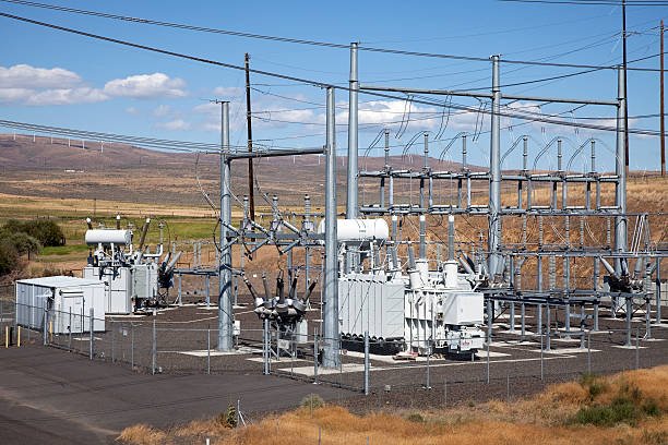
Power transformers are the backbone of electrical transmission and distribution systems, but many buyers and engineers focus only on voltage ratings and capacity without understanding what makes these machines reliable. Each component inside a power transformer plays a specific role in insulation, cooling, voltage regulation, or protection. Failing to understand these parts can make maintenance more difficult, increase the risk of unexpected failures, and complicate purchasing decisions. Knowing the main components of a power transformer helps you evaluate product quality, improve maintenance planning, and select the right transformer for your application.
The main components found in a power transformer include the magnetic core, primary and secondary windings, insulating system, transformer tank, cooling system, bushings, tap changer, conservator tank, protection devices, and monitoring instruments. Together, these components enable efficient voltage transformation, provide electrical insulation, dissipate heat, protect the transformer from faults, and ensure reliable long-term operation in power transmission and distribution networks.
Although every transformer is designed to meet specific electrical requirements, the core components remain largely the same. Understanding the function of each part provides valuable insight into how power transformers operate and why proper design and maintenance are essential for long service life.
What Are the Main Components Found in a Power Transformer?
Power transformers are among the most critical assets in electrical transmission and distribution systems. Their ability to efficiently transfer electrical energy between voltage levels depends on a series of carefully engineered components working together as an integrated system. While the transformer core and windings perform the actual voltage transformation, numerous auxiliary components—including the insulation system, tank, cooling equipment, bushings, tap changer, and protection devices—are equally important for ensuring reliable, safe, and long-lasting operation. Understanding the function of each component helps engineers, operators, and buyers make informed decisions regarding transformer selection, maintenance, and lifecycle management.
The main components of a power transformer include the magnetic core, primary and secondary windings, insulation system, insulating liquid, transformer tank, cooling system, bushings, tap changer, conservator, breather, protection devices, monitoring instruments, and structural accessories. Together, these components provide voltage transformation, electrical insulation, heat dissipation, mechanical protection, and operational safety.
The transformer core and windings are the only components that determine transformer performance.False
While the core and windings perform energy conversion, the insulation system, cooling equipment, protection devices, bushings, and accessories are equally essential for ensuring reliable, efficient, and safe long-term operation.
Magnetic core
The magnetic core is the central component of a power transformer and provides the low-reluctance path for magnetic flux generated by the primary winding.
Its primary functions include:
- Conducting magnetic flux efficiently
- Minimizing hysteresis and eddy current losses
- Supporting high transformer efficiency
- Providing mechanical support for windings
Modern transformer cores are typically manufactured from grain-oriented silicon steel laminations or amorphous metal in high-efficiency designs.
Core characteristics
| Feature | Function |
|---|---|
| Laminated steel | Reduces eddy current losses |
| Grain-oriented material | Improves magnetic efficiency |
| Step-lap construction | Reduces noise and losses |
| Rigid clamping | Maintains mechanical stability |
Primary and secondary windings
The windings transfer electrical energy through electromagnetic induction.
The primary winding receives electrical power, while the secondary winding delivers transformed voltage to the load.
Windings are commonly manufactured using:
- Copper conductors
- Aluminum conductors
- Paper insulation
- Epoxy-coated insulation systems
Their design influences:
- Voltage regulation
- Efficiency
- Short-circuit strength
- Thermal performance
Insulation system
The insulation system electrically separates energized components while withstanding operating and transient voltages.
It consists of:
- Solid insulation
- Paper insulation
- Pressboard
- Spacers
- Barriers
A high-quality insulation system prevents electrical breakdown and significantly extends transformer service life.
Insulating liquid
Most power transformers use insulating liquid for both electrical insulation and cooling.
Common insulating fluids include:
- Mineral oil
- Natural ester fluid
- Synthetic ester fluid
- Silicone insulating liquid (special applications)
The insulating liquid performs several important functions:
- Removes heat from windings
- Provides dielectric insulation
- Suppresses electrical discharges
- Protects insulation materials from oxidation
Transformer tank
The transformer tank provides mechanical protection and contains the core, windings, and insulating liquid.
Its functions include:
- Supporting internal components
- Preventing oil leakage
- Withstanding internal pressure
- Protecting against environmental exposure
Tank construction must accommodate thermal expansion and mechanical stresses during transportation and operation.
Tank functions
| Component Feature | Purpose |
|---|---|
| Welded steel construction | Structural strength |
| Corrosion-resistant coating | Long-term durability |
| Pressure resistance | Safe operation |
| Oil-tight sealing | Prevents contamination |
Cooling system
Heat generated by transformer losses must be removed efficiently.
Cooling equipment may include:
- Radiators
- Cooling fins
- Cooling fans
- Oil pumps
- Water heat exchangers (large units)
Common cooling methods include:
- ONAN (Oil Natural Air Natural)
- ONAF (Oil Natural Air Forced)
- OFAF (Oil Forced Air Forced)
- OFWF (Oil Forced Water Forced)
Proper cooling extends insulation life and improves overload capability.
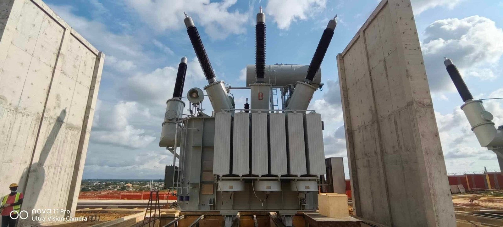
Bushings
Bushings allow electrical conductors to safely pass through the grounded transformer tank.
They provide:
- High-voltage insulation
- Mechanical support
- Weather resistance
- Electrical connection to external systems
Bushings are among the most highly stressed insulation components in a transformer.
Tap changer
A tap changer adjusts the transformer's turns ratio to maintain stable output voltage.
Two primary types are used:
- Off-circuit tap changer (OCTC)
- On-load tap changer (OLTC)
The tap changer compensates for:
- Load variation
- Grid voltage fluctuations
- Seasonal demand changes
Voltage regulation is especially important in transmission and distribution systems.
Conservator tank
Many oil-filled transformers include a conservator to accommodate oil expansion and contraction as temperature changes.
Its benefits include:
- Maintaining proper oil level
- Reducing oxidation
- Limiting moisture ingress
- Extending insulating oil life
A conservator is often connected to the main tank through a pipe equipped with a Buchholz relay.
Breather
The breather removes moisture from air entering the conservator during oil volume changes.
It typically contains silica gel, which:
- Absorbs moisture
- Protects insulation quality
- Reduces oil contamination
Moisture control is essential because water significantly reduces dielectric strength.
Protection devices
Power transformers incorporate multiple protective devices to detect abnormal operating conditions.
Typical protection equipment includes:
- Buchholz relay
- Pressure relief device
- Sudden pressure relay
- Oil level indicator
- Temperature indicators
- Gas monitoring systems
These devices improve reliability by detecting developing faults before catastrophic failures occur.
Common protection equipment
| Protection Device | Function |
|---|---|
| Buchholz relay | Detects internal gas generation |
| Pressure relief device | Releases excessive internal pressure |
| Oil level gauge | Monitors insulating liquid level |
| Temperature indicator | Tracks operating temperature |
Monitoring instruments
Modern power transformers increasingly incorporate digital monitoring technologies.
Typical monitoring systems include:
- Winding temperature sensors
- Oil temperature sensors
- Dissolved gas analysis (DGA)
- Moisture-in-oil sensors
- Load monitoring
- Online condition monitoring
These systems support predictive maintenance and reduce unexpected outages.
Structural accessories
Numerous structural components contribute to safe installation and maintenance.
Examples include:
- Lifting lugs
- Jacking pads
- Ground terminals
- Nameplate
- Drain valves
- Sampling valves
- Inspection covers
- Cable boxes
Although these accessories do not directly influence electrical performance, they improve installation, operation, and maintenance efficiency.
How the components work together
Each transformer component performs a specific function while supporting the operation of the entire system.
| Component | Primary Role |
|---|---|
| Core | Guides magnetic flux |
| Windings | Transfer electrical energy |
| Insulation system | Prevents electrical breakdown |
| Insulating liquid | Provides insulation and cooling |
| Tank | Mechanical protection |
| Cooling system | Removes heat |
| Bushings | External electrical connections |
| Tap changer | Voltage regulation |
| Conservator | Oil expansion control |
| Protection devices | Fault detection |
| Monitoring instruments | Condition assessment |
The reliability of a power transformer depends on the proper interaction of all these components rather than any single part alone.
Factors influencing component selection
Transformer component design depends on several project-specific factors, including:
- Rated power
- System voltage
- Cooling requirements
- Installation environment
- Short-circuit withstand capability
- Applicable standards
- Maintenance strategy
- Expected service life
Careful engineering ensures that each component is appropriately sized and coordinated with the rest of the transformer.
What Is the Function of the Transformer Core and Windings?
The transformer core and windings are the two primary components responsible for transferring electrical energy from one circuit to another through electromagnetic induction. The core provides a low-reluctance path for magnetic flux, while the windings generate and receive that magnetic flux to transform voltage levels. Together, they determine a transformer's efficiency, voltage regulation, thermal performance, short-circuit strength, and overall reliability. Although a transformer contains many auxiliary components, the core and windings form the heart of its electrical operation.
The transformer core guides magnetic flux between the primary and secondary windings, while the windings transfer electrical energy through electromagnetic induction. The core minimizes magnetic losses, and the windings convert electrical energy from one voltage level to another with high efficiency. Their combined design directly influences transformer performance, efficiency, temperature rise, and service life.
The transformer core generates electrical power, while the windings only provide mechanical support.False
The core does not generate power. It provides a low-reluctance magnetic path, while the primary and secondary windings transfer electrical energy through electromagnetic induction based on the transformer's turns ratio.
What is the function of the transformer core?
The transformer core serves as the magnetic circuit of the transformer.
Its primary purpose is to provide an efficient path for the alternating magnetic flux produced by the primary winding.
The core performs several critical functions:
- Conducts magnetic flux efficiently
- Reduces magnetic reluctance
- Minimizes hysteresis losses
- Minimizes eddy current losses
- Supports the windings mechanically
- Improves overall transformer efficiency
Without the core, much of the magnetic field would disperse into the surrounding air, significantly reducing efficiency.
Main functions of the core
| Function | Benefit |
|---|---|
| Provides magnetic path | Efficient flux transfer |
| Reduces magnetic losses | Higher efficiency |
| Supports windings | Improved mechanical stability |
| Concentrates magnetic field | Better voltage transformation |
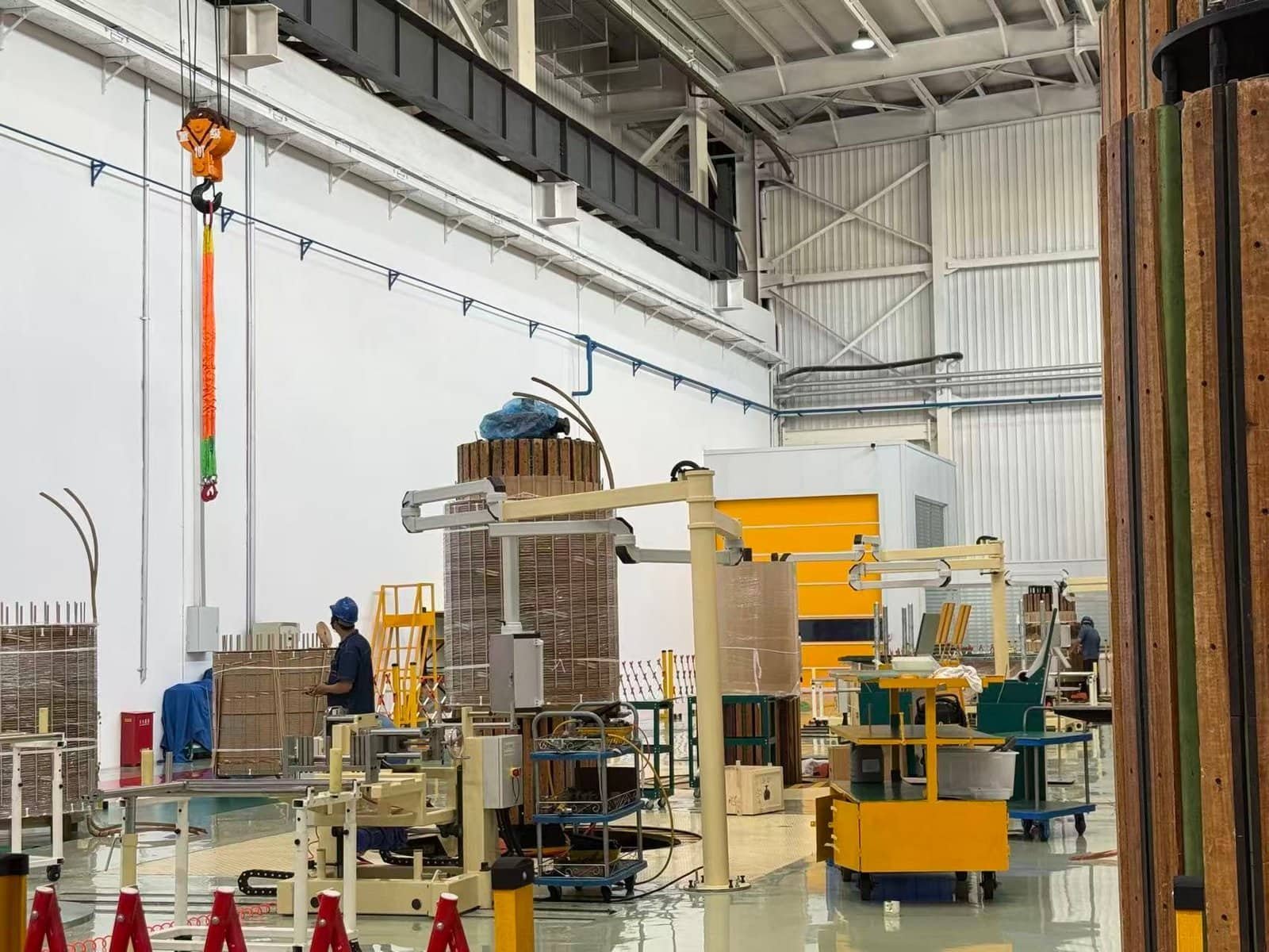
How is the transformer core constructed?
Modern transformer cores are manufactured using thin laminated sheets of high-grade electrical steel.
Typical materials include:
- Grain-oriented silicon steel
- Amorphous metal (high-efficiency designs)
The laminations are insulated from each other to reduce circulating eddy currents.
Important construction features include:
- Step-lap joints
- Laminated construction
- Precision stacking
- Mechanical clamping
These features improve efficiency while reducing vibration and audible noise.
Why are laminations necessary?
Alternating magnetic fields naturally induce circulating currents inside conductive materials.
Laminating the core reduces these unwanted currents by increasing their electrical resistance.
Benefits include:
- Lower eddy current losses
- Reduced heat generation
- Improved efficiency
- Longer insulation life
Without laminations, transformer losses would increase dramatically.
What is the function of the windings?
The windings are responsible for transferring electrical energy between circuits through electromagnetic induction.
Every transformer contains at least two windings:
- Primary winding
- Secondary winding
The primary winding receives electrical power from the source.
The secondary winding delivers transformed electrical power to the connected load.
How do the windings transfer electrical energy?
When alternating current flows through the primary winding, it produces an alternating magnetic field.
That magnetic field passes through the transformer core and induces voltage in the secondary winding.
The relationship between voltage and the number of turns is:
[\frac{V_p}{V_s}=\frac{N_p}{N_s}]
Where:
- (V_p) = Primary voltage
- (V_s) = Secondary voltage
- (N_p) = Primary turns
- (N_s) = Secondary turns
This turns ratio determines whether the transformer steps voltage up or down.
Primary winding
The primary winding performs several functions:
- Receives incoming electrical energy
- Produces alternating magnetic flux
- Transfers energy into the magnetic circuit
Its design depends on:
- System voltage
- Current rating
- Insulation level
- Thermal requirements
Secondary winding
The secondary winding converts magnetic energy back into electrical energy.
Its functions include:
- Delivering output voltage
- Supplying load current
- Maintaining voltage regulation
- Supporting system stability
The secondary winding is designed according to the required output voltage and current.
Winding conductor materials
Transformer windings are commonly manufactured using either copper or aluminum conductors.
Conductor comparison
| Material | Advantages | Considerations |
|---|---|---|
| Copper | Higher conductivity, excellent mechanical strength | Higher cost |
| Aluminum | Lower weight, lower material cost | Larger conductor size required |
Copper remains the preferred choice for many power transformers because of its excellent electrical and mechanical properties.
Winding insulation
The conductors are insulated to prevent electrical breakdown between turns and between windings.
Common insulation materials include:
- Cellulose paper
- Pressboard
- Epoxy resin
- Nomex® insulation
- High-temperature polymers
The insulation system significantly influences transformer lifespan.
Interaction between the core and windings
Neither the core nor the windings can perform voltage transformation independently.
The process works as follows:
- Alternating current enters the primary winding.
- The primary winding generates magnetic flux.
- The core channels the magnetic flux efficiently.
- The flux links the secondary winding.
- Voltage is induced in the secondary winding.
- Electrical power is delivered to the load.
This coordinated operation enables efficient power transfer with no direct electrical connection between the two circuits.
Core and winding interaction
| Component | Primary Function |
|---|---|
| Core | Guides magnetic flux |
| Primary winding | Creates magnetic field |
| Secondary winding | Receives induced voltage |
| Insulation | Prevents electrical breakdown |
How do the core and windings affect transformer efficiency?
Transformer efficiency depends heavily on minimizing losses in both components.
Core-related losses include:
- Hysteresis loss
- Eddy current loss
Winding-related losses include:
- Copper (I²R) losses
- Stray losses
- Additional heating under harmonic loads
Modern transformer designs reduce these losses through:
- High-grade core materials
- Optimized conductor geometry
- Improved insulation systems
- Precision manufacturing
How do they influence temperature rise?
Both components generate heat during operation.
The core produces heat due to magnetic losses.
The windings generate heat because of electrical resistance.
Effective cooling systems remove this heat to:
- Protect insulation
- Maintain efficiency
- Extend service life
- Improve overload capability
Thermal design is therefore closely linked to both core and winding performance.
Factors affecting core and winding design
Transformer manufacturers optimize these components based on:
- Rated power
- System voltage
- Frequency
- Cooling method
- Short-circuit withstand requirements
- Efficiency targets
- Applicable international standards
Each design parameter influences the final performance of the transformer.
Summary of core and winding functions
| Component | Main Function | Contribution |
|---|---|---|
| Magnetic core | Conducts magnetic flux | High efficiency and low losses |
| Primary winding | Receives input power | Generates magnetic field |
| Secondary winding | Supplies output power | Delivers transformed voltage |
| Insulation system | Electrically separates conductors | Safe and reliable operation |
Together, these components perform the fundamental task of voltage transformation while ensuring safe, efficient, and reliable operation.
How Do the Cooling and Insulation Systems Protect a Power Transformer?

Power transformers operate continuously under high electrical and thermal stress. During operation, electrical losses in the core and windings generate heat, while high operating voltages place constant stress on the insulation system. Without effective cooling and insulation, excessive temperatures and electrical breakdown could rapidly damage the transformer, leading to reduced efficiency, insulation aging, unexpected outages, or catastrophic failure. Together, the cooling and insulation systems form the foundation of transformer reliability, ensuring safe operation throughout decades of service.
The cooling system protects a power transformer by removing heat generated by core and winding losses, while the insulation system prevents electrical breakdown between energized components and the grounded structure. Working together, these systems maintain safe operating temperatures, preserve dielectric strength, extend insulation life, improve efficiency, and ensure long-term transformer reliability.
The cooling system only improves transformer efficiency, while the insulation system only prevents electric shock.False
The cooling system primarily controls operating temperature to prevent thermal damage, while the insulation system electrically isolates energized components to prevent internal faults and dielectric failure. Both systems are essential for safe, reliable transformer operation.
Why are cooling and insulation systems essential?
A power transformer is exposed to two major operational stresses:
- Thermal stress caused by electrical losses
- Electrical stress caused by operating voltage and transient overvoltages
The cooling system manages heat, while the insulation system withstands electrical stress. Neither system can ensure reliable operation on its own.
Primary protective functions
| System | Primary Function |
|---|---|
| Cooling system | Removes heat from the transformer |
| Insulation system | Prevents electrical breakdown |
| Combined effect | Protects transformer reliability and extends service life |
Together, they allow the transformer to operate safely under varying load conditions.
How the cooling system protects the transformer
Whenever current flows through the windings and magnetic flux passes through the core, electrical losses generate heat.
Major heat sources include:
- Core (no-load) losses
- Copper (load) losses
- Stray losses
- Eddy current losses
If this heat is not removed effectively:
- Insulation ages more rapidly
- Winding temperatures increase
- Efficiency decreases
- Mechanical stresses rise
- Failure risk increases
The cooling system continuously transfers heat away from the transformer.
Components of the cooling system
Depending on transformer size, cooling equipment may include:
- Transformer oil
- Radiators
- Cooling fins
- Cooling fans
- Oil pumps
- Water heat exchangers
Each component contributes to efficient heat dissipation.
Cooling component functions
| Component | Function |
|---|---|
| Insulating liquid | Transfers heat from windings and core |
| Radiators | Dissipate heat to surrounding air |
| Cooling fans | Increase airflow |
| Oil pumps | Improve oil circulation |
| Heat exchangers | Enhance cooling in large transformers |
Common transformer cooling methods
Power transformers use standardized cooling classifications.
Typical methods include:
- ONAN (Oil Natural Air Natural)
- ONAF (Oil Natural Air Forced)
- OFAF (Oil Forced Air Forced)
- OFWF (Oil Forced Water Forced)
Higher-capacity transformers generally require more advanced cooling systems to maintain acceptable operating temperatures.
Benefits of effective cooling
An efficient cooling system provides several important advantages:
- Lower operating temperatures
- Longer insulation life
- Improved efficiency
- Higher continuous load capability
- Better overload performance
- Reduced maintenance costs
Keeping temperatures under control is one of the most effective ways to maximize transformer service life.
How the insulation system protects the transformer
The insulation system electrically separates conductive components operating at different voltage potentials.
It prevents:
- Short circuits
- Flashovers
- Partial discharge
- Dielectric breakdown
- Internal electrical faults
Without adequate insulation, voltage differences inside the transformer would quickly lead to catastrophic failure.
Components of the insulation system
Transformer insulation combines both solid and liquid insulating materials.
Typical components include:
- Cellulose paper
- Pressboard
- Insulating barriers
- Spacers
- Transformer oil or alternative insulating fluids
- Bushings
Each material contributes to the overall dielectric strength of the transformer.
Insulation materials
| Material | Purpose |
|---|---|
| Cellulose paper | Conductor insulation |
| Pressboard | Mechanical and electrical insulation |
| Transformer oil | Liquid dielectric and cooling medium |
| Bushings | Insulated external electrical connections |
Electrical protection provided by insulation
The insulation system must withstand several types of electrical stress:
- Rated operating voltage
- Lightning impulses
- Switching surges
- Temporary overvoltages
- Short-circuit mechanical forces
A properly designed insulation system ensures that these stresses do not cause dielectric failure.
Thermal protection of insulation
Although insulation prevents electrical breakdown, excessive temperature gradually degrades insulating materials.
High temperatures accelerate:
- Paper aging
- Oxidation
- Moisture generation
- Loss of dielectric strength
This illustrates why cooling and insulation cannot be considered separately.
The cooling system protects the insulation by limiting thermal aging.
How cooling and insulation work together
The two systems are closely interconnected.
The cooling system:
- Removes heat from the core and windings
- Protects insulation from overheating
- Maintains dielectric performance
The insulation system:
- Prevents electrical faults
- Enables safe voltage isolation
- Protects conductive components
System interaction
| Cooling System Role | Insulation System Role |
|---|---|
| Controls temperature | Prevents electrical breakdown |
| Removes internal heat | Isolates energized parts |
| Slows insulation aging | Maintains dielectric strength |
| Supports long service life | Ensures safe operation |
Together, they determine much of a transformer's operational reliability.
Monitoring cooling and insulation performance
Modern power transformers are equipped with monitoring devices that continuously assess both systems.
Common monitoring equipment includes:
- Oil temperature indicators
- Winding temperature indicators
- Cooling fan controls
- Dissolved Gas Analysis (DGA)
- Moisture sensors
- Partial discharge monitoring
- Online condition monitoring systems
These technologies help identify developing problems before failures occur.
Factors affecting cooling and insulation performance
Several operating conditions influence both systems:
- Ambient temperature
- Transformer loading
- Altitude
- Moisture ingress
- Oil quality
- Ventilation
- Contamination
- Maintenance practices
Proper installation and preventive maintenance help preserve system performance throughout the transformer's life.
Consequences of cooling or insulation failure
Failure of either system can have serious consequences.
Possible results include:
- Overheating
- Accelerated insulation aging
- Partial discharge
- Internal arcing
- Oil decomposition
- Reduced efficiency
- Unexpected outages
- Complete transformer failure
Routine inspection and condition monitoring significantly reduce these risks.
Summary of protective functions
| Protection Objective | Cooling System | Insulation System |
|---|---|---|
| Heat removal | ✔ | — |
| Electrical isolation | — | ✔ |
| Temperature control | ✔ | Indirect |
| Dielectric strength | Indirect | ✔ |
| Service life extension | ✔ | ✔ |
| Reliability improvement | ✔ | ✔ |
Both systems are indispensable to the safe and efficient operation of a power transformer.
Why Are Bushings, Tap Changers, and Conservator Tanks Important?

Although the core and windings perform the fundamental task of voltage transformation, several auxiliary components are essential for ensuring a power transformer operates safely, efficiently, and reliably. Among the most important are the bushings, tap changer, and conservator tank. Bushings provide insulated electrical connections between the transformer and the external power system, tap changers maintain stable output voltage despite fluctuations in supply or load, and conservator tanks protect the insulating oil from oxidation while accommodating thermal expansion. Together, these components enhance operational reliability, extend equipment life, and support stable power delivery.
Bushings, tap changers, and conservator tanks are critical because they enable safe electrical connections, regulate transformer output voltage, and preserve the quality of insulating oil. These components improve transformer reliability, operational flexibility, insulation life, and long-term performance while reducing the risk of faults and premature aging.
Bushings, tap changers, and conservator tanks are optional accessories that have little impact on transformer performance.False
These components play essential roles in electrical insulation, voltage regulation, and insulating oil preservation. Their proper design and maintenance are vital for the safe and reliable operation of most oil-immersed power transformers.
Why are bushings important?
Bushings provide a safe path for electrical conductors to pass through the grounded transformer tank without creating an electrical short circuit.
Since the transformer tank is grounded and the conductors carry high voltage, effective insulation is essential.
Bushings perform several key functions:
- Insulate high-voltage conductors
- Support external electrical connections
- Prevent flashover between conductors and the tank
- Withstand electrical and mechanical stresses
- Protect against weather and environmental contamination
Without bushings, it would be impossible to safely connect the transformer to the power network.
Main functions of bushings
| Function | Benefit |
|---|---|
| Electrical insulation | Prevents short circuits |
| Mechanical support | Holds conductors securely |
| External connection | Connects transformer to the grid |
| Environmental protection | Resists moisture and contamination |
Types of transformer bushings
The type of bushing selected depends on the voltage level and transformer application.
Common types include:
- Porcelain bushings
- Resin-impregnated paper (RIP) bushings
- Resin-impregnated synthetic (RIS) bushings
- Oil-impregnated paper (OIP) bushings
Higher-voltage transformers typically use condenser bushings to distribute the electric field more uniformly and improve dielectric performance.
How bushings improve transformer reliability
Bushings are designed to withstand:
- Rated operating voltage
- Lightning impulse voltages
- Switching surges
- Mechanical loads from connected conductors
- Environmental exposure
Properly designed bushings reduce the risk of insulation failure and improve overall system reliability.
Why are tap changers important?
Power system voltage varies continuously due to changes in:
- Load demand
- Transmission conditions
- Generator output
- Seasonal operating patterns
A tap changer adjusts the transformer's turns ratio to compensate for these variations and maintain the desired secondary voltage.
Without voltage regulation, sensitive electrical equipment may experience poor performance or damage.
How does a tap changer work?
A tap changer changes the effective number of turns in one of the transformer windings.
This alters the voltage ratio between the primary and secondary windings.
By selecting different taps, the transformer can:
- Increase output voltage
- Decrease output voltage
- Maintain stable voltage under varying operating conditions
Voltage regulation improves both power quality and system stability.
Types of tap changers
| Type | Characteristics | Typical Application |
|---|---|---|
| Off-circuit tap changer (OCTC) | Operated only when de-energized | Distribution transformers |
| On-load tap changer (OLTC) | Operated while energized | Power and transmission transformers |
On-load tap changers are widely used in transmission networks because they allow continuous voltage adjustment without interrupting service.
Benefits of tap changers
A properly designed tap changer offers several operational advantages:
- Stable secondary voltage
- Improved power quality
- Better load regulation
- Enhanced grid stability
- Greater operational flexibility
Modern OLTC systems can automatically adjust taps in response to changing network conditions.
Why is the conservator tank important?
Transformer insulating oil expands when heated and contracts when cooled.
A conservator tank provides space for these volume changes without exposing the main transformer tank directly to outside air.
This helps maintain:
- Proper oil level
- Internal pressure stability
- Oil quality
- Insulation performance
The conservator is especially important for extending the service life of both the insulating oil and the cellulose insulation.
How the conservator tank works
The conservator is connected to the main transformer tank through a pipe.
As the transformer warms during operation:
- Oil expands into the conservator.
As the transformer cools:
- Oil returns to the main tank.
In many designs, the conservator works together with a breather containing silica gel, which removes moisture from incoming air.
This minimizes contamination of the insulating oil.
Benefits of the conservator tank
The conservator tank provides several important advantages:
- Accommodates thermal expansion
- Reduces oil oxidation
- Limits moisture ingress
- Preserves dielectric strength
- Extends oil service life
- Protects paper insulation
Conservator functions
| Function | Benefit |
|---|---|
| Oil expansion space | Prevents excessive pressure |
| Oil preservation | Reduces oxidation |
| Moisture control | Protects insulation |
| Pressure stabilization | Improves reliability |
How these components work together
Although each component performs a different function, they collectively support reliable transformer operation.
- Bushings provide safe electrical interfaces.
- Tap changers maintain voltage stability.
- Conservator tanks protect the insulating oil and insulation system.
Together, they improve:
- Electrical safety
- Voltage regulation
- Insulation performance
- Operational reliability
- Equipment lifespan
Their coordinated operation helps ensure consistent transformer performance under changing operating conditions.
Monitoring and maintenance considerations
Regular inspection of these components is essential for long-term reliability.
Typical maintenance activities include:
Bushings
- Visual inspection for cracks or contamination
- Insulation resistance testing
- Power factor (tan δ) measurements
- Thermal imaging
Tap changers
- Contact wear inspection
- Motor drive testing
- Oil quality monitoring (for OLTC compartments)
- Operational timing verification
Conservator tanks
- Oil level inspection
- Breather silica gel replacement
- Leak detection
- Diaphragm or bladder inspection (where fitted)
Routine maintenance helps identify developing issues before they affect transformer performance.
Consequences of component failure
Failure of any of these components can significantly impact transformer operation.
| Component | Possible Consequences of Failure |
|---|---|
| Bushing | Flashover, insulation failure, transformer outage |
| Tap changer | Poor voltage regulation, contact damage, overheating |
| Conservator tank | Oil contamination, accelerated insulation aging, reduced dielectric strength |
Preventive maintenance and condition monitoring are essential to minimize these risks.
Factors influencing component selection
The design and specification of bushings, tap changers, and conservator tanks depend on several factors, including:
- Rated voltage
- Transformer capacity
- Cooling method
- Installation environment
- Utility operating practices
- Grid voltage regulation requirements
- Applicable international standards
Selecting components that match the application's electrical and environmental demands helps maximize transformer reliability and service life.
What Protection and Monitoring Devices Are Installed in Power Transformers?
Power transformers operate continuously under high electrical, thermal, and mechanical stresses, making protection and monitoring systems essential for safe and reliable operation. While the transformer itself is designed to withstand normal operating conditions, abnormal events such as internal faults, overheating, insulation deterioration, overloading, lightning surges, and cooling failures can significantly shorten its service life or lead to catastrophic failure. To minimize these risks, modern power transformers are equipped with a range of protection devices that isolate faults and monitoring systems that continuously assess the transformer's health.
Power transformers are equipped with protection devices such as Buchholz relays, pressure relief devices, differential protection, overcurrent relays, temperature indicators, and surge arresters, along with monitoring systems including oil level gauges, dissolved gas analysis (DGA), winding temperature monitors, moisture sensors, and online condition monitoring. Together, these devices detect faults early, protect critical components, and improve operational reliability.
Power transformers only require circuit breakers for protection because all internal faults are cleared externally.False
While circuit breakers isolate faulted equipment, transformers require dedicated internal protection and monitoring devices to detect gas generation, overheating, insulation deterioration, pressure rise, and other conditions before severe damage occurs.
Why are protection and monitoring devices necessary?
Power transformers represent major capital investments and are expected to operate reliably for 30 years or more.
Protection and monitoring systems help to:
- Detect developing faults
- Prevent catastrophic failures
- Minimize outage duration
- Improve operational safety
- Extend transformer service life
- Reduce maintenance costs
Early fault detection allows corrective action before minor problems develop into major failures.
Protection versus monitoring
| System | Primary Purpose |
|---|---|
| Protection devices | Detect faults and initiate isolation |
| Monitoring devices | Assess transformer condition continuously |
| Combined benefit | Improved reliability and asset management |
Buchholz relay
The Buchholz relay is one of the most important protection devices used in oil-immersed transformers equipped with a conservator tank.
It detects:
- Gas generated by insulation deterioration
- Minor internal faults
- Serious internal arcing
- Oil flow caused by severe faults
The relay typically provides:
- Alarm for slow gas accumulation
- Trip signal for rapid oil movement caused by major internal faults
Because it responds before many faults become catastrophic, the Buchholz relay significantly improves transformer protection.
Pressure relief device (PRD)
Internal faults can rapidly increase pressure inside the transformer tank.
The pressure relief device protects the tank by:
- Releasing excessive internal pressure
- Preventing tank rupture
- Reducing explosion risk
Many modern PRDs also include electrical contacts that send alarm or trip signals to the protection system.
Oil level indicator
Maintaining the correct insulating oil level is essential for both insulation and cooling.
Oil level indicators monitor:
- Normal oil level
- Low oil conditions
- Excessively high oil levels
Abnormal oil levels may indicate:
- Leakage
- Thermal expansion issues
- Conservator problems
Continuous monitoring helps prevent insulation exposure and cooling deficiencies.
Oil temperature indicator (OTI)
The oil temperature indicator measures the temperature of the top insulating oil.
It provides:
- Local temperature indication
- High-temperature alarms
- Cooling fan control
- Trip signals (if necessary)
High oil temperature may indicate:
- Overloading
- Cooling system malfunction
- Internal faults
Winding temperature indicator (WTI)
The winding temperature indicator estimates or directly measures the hottest part of the transformer windings.
Compared with oil temperature, winding temperature responds more quickly to load changes.
Typical functions include:
- Continuous temperature monitoring
- Alarm activation
- Automatic cooling control
- Emergency trip initiation
Keeping winding temperatures within design limits helps preserve insulation life.
Temperature monitoring devices
| Device | Monitored Parameter |
|---|---|
| Oil Temperature Indicator | Top oil temperature |
| Winding Temperature Indicator | Winding hot-spot temperature |
| Ambient Temperature Sensor | Surrounding air temperature |
Differential protection relay
Differential protection is the primary electrical protection for internal transformer faults.
It compares:
- Current entering the transformer
- Current leaving the transformer
Under normal conditions, these currents are balanced.
If an internal fault occurs, the difference exceeds a preset threshold, and the relay initiates an immediate trip.
Differential protection is highly sensitive and provides fast fault clearance.
Overcurrent and earth fault protection
Overcurrent relays protect transformers against excessive current caused by:
- External faults
- Sustained overloads
- Short circuits
Earth fault protection detects current flowing to ground due to insulation failure.
Together, these relays provide backup protection for both internal and external fault conditions.
Surge arresters
Power transformers are vulnerable to transient overvoltages caused by:
- Lightning strikes
- Switching operations
- Network disturbances
Surge arresters limit these voltage spikes before they reach the transformer insulation.
Benefits include:
- Reduced insulation stress
- Prevention of flashover
- Longer transformer lifespan
They are typically installed near the transformer bushings.
Dissolved Gas Analysis (DGA)
DGA is one of the most valuable condition-monitoring techniques for oil-filled transformers.
It analyzes gases dissolved in the insulating oil, including:
- Hydrogen
- Methane
- Ethane
- Ethylene
- Acetylene
- Carbon monoxide
- Carbon dioxide
Different gas patterns indicate different fault types, such as:
- Partial discharge
- Thermal overheating
- Electrical arcing
- Cellulose insulation degradation
Online DGA systems provide continuous transformer health assessment.
Common gases and possible indications
| Gas | Typical Indication |
|---|---|
| Hydrogen | Partial discharge |
| Methane | Low-temperature overheating |
| Ethylene | High-temperature overheating |
| Acetylene | Electrical arcing |
| Carbon monoxide | Paper insulation aging |
Moisture monitoring
Moisture significantly reduces the dielectric strength of transformer insulation.
Modern monitoring systems measure:
- Moisture in oil
- Moisture in paper insulation
- Relative saturation
Maintaining low moisture levels improves insulation performance and extends service life.
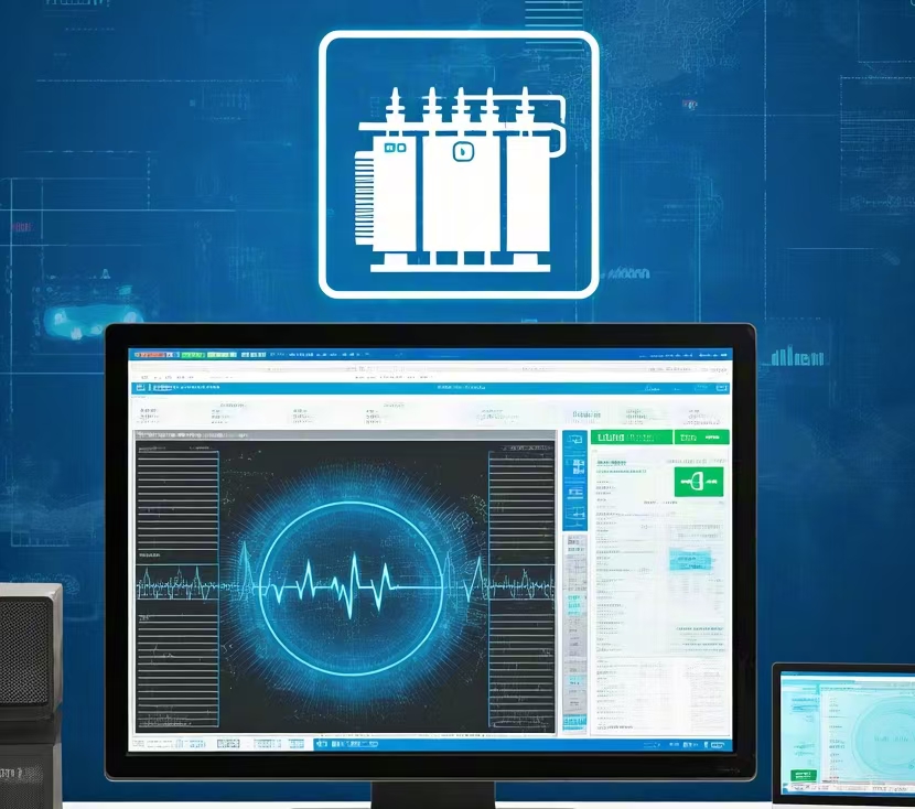
Online condition monitoring systems
Modern digital transformers increasingly use integrated monitoring platforms.
Typical monitored parameters include:
- Oil temperature
- Winding temperature
- Load current
- Oil level
- Moisture
- DGA results
- Cooling system status
- Bushing condition
- Partial discharge activity
These systems enable predictive maintenance by identifying trends before failures occur.
Cooling system monitoring
Reliable cooling is essential for transformer performance.
Monitoring devices supervise:
- Fan operation
- Oil pump operation
- Cooling stage control
- Heat exchanger performance
Automatic control systems activate additional cooling when transformer loading increases.
Bushing monitoring
Bushings are among the most stressed insulation components in a transformer.
Advanced monitoring systems can detect:
- Insulation deterioration
- Increased dielectric losses
- Partial discharge
- Capacitance changes
Continuous monitoring helps prevent unexpected bushing failures.
Protection and monitoring summary
| Device | Primary Function |
|---|---|
| Buchholz relay | Detects internal gas generation and oil movement |
| Pressure relief device | Prevents excessive tank pressure |
| Oil level indicator | Monitors insulating oil level |
| Oil temperature indicator | Monitors top oil temperature |
| Winding temperature indicator | Monitors winding hot-spot temperature |
| Differential relay | Detects internal electrical faults |
| Overcurrent relay | Protects against excessive current |
| Earth fault relay | Detects ground faults |
| Surge arrester | Protects against transient overvoltages |
| DGA monitor | Detects insulation deterioration and internal faults |
| Moisture sensor | Monitors insulation moisture |
| Cooling system monitor | Supervises cooling equipment performance |
Benefits of comprehensive monitoring
Installing modern protection and monitoring systems offers several advantages:
- Earlier fault detection
- Reduced unplanned outages
- Improved operational safety
- Lower maintenance costs
- Better asset management
- Extended transformer lifespan
- Increased power system reliability
These benefits are especially valuable for critical infrastructure and high-value power transformers.
How Do Power Transformer Components Affect Performance and Service Life?
The performance and longevity of a power transformer depend not only on its overall design but also on the quality, condition, and interaction of its individual components. Every major component—from the magnetic core and windings to the insulation system, cooling equipment, bushings, tap changer, and protection devices—contributes to the transformer's efficiency, voltage regulation, thermal stability, and operational reliability. A weakness in any single component can increase losses, accelerate insulation aging, reduce load capacity, or even lead to premature transformer failure. Understanding how these components influence performance helps operators optimize maintenance strategies and maximize asset life.
Power transformer components affect performance and service life by influencing electrical efficiency, heat dissipation, insulation integrity, voltage regulation, mechanical strength, and fault protection. High-quality components, proper maintenance, and effective monitoring reduce energy losses, slow insulation aging, improve reliability, and enable transformers to operate safely for 30 years or more.
A power transformer's service life depends almost entirely on the condition of its windings.False
While windings are critical, transformer longevity depends on the combined performance of the core, insulation system, cooling equipment, bushings, tap changer, protective devices, and maintenance practices. Failure of any major component can significantly reduce transformer life.
How does the magnetic core affect performance?
The magnetic core forms the foundation of electromagnetic energy transfer.
Its design directly influences:
- No-load losses
- Transformer efficiency
- Noise level
- Operating temperature
- Mechanical vibration
High-quality grain-oriented silicon steel and precision core assembly reduce hysteresis and eddy current losses, improving efficiency and lowering operating temperatures.
Impact of the core on transformer performance
| Core Characteristic | Effect on Performance |
|---|---|
| Low-loss material | Higher efficiency |
| Precision lamination | Reduced eddy current losses |
| Step-lap joints | Lower vibration and noise |
| Rigid clamping | Improved mechanical stability |
A well-designed core minimizes energy losses throughout the transformer's operating life.
How do the windings influence efficiency and reliability?
The primary and secondary windings are responsible for transferring electrical energy through electromagnetic induction.
Their design affects:
- Copper losses
- Voltage regulation
- Short-circuit strength
- Thermal performance
- Load capacity
High-conductivity copper conductors, optimized winding geometry, and robust insulation improve both electrical efficiency and mechanical durability.
Poor winding design can result in excessive heating, higher losses, and reduced service life.
Why is the insulation system so critical?
The insulation system protects the transformer from electrical breakdown by isolating energized components.
It must withstand:
- Continuous operating voltage
- Lightning impulses
- Switching surges
- Mechanical forces during faults
The condition of paper insulation is often considered the primary indicator of transformer aging because it cannot be replaced without major rebuilding.
Factors that accelerate insulation deterioration include:
- High temperature
- Moisture
- Oxygen
- Contamination
- Electrical discharge
Maintaining insulation integrity is essential for extending transformer life.
How does the cooling system extend service life?
Heat is one of the greatest enemies of transformer insulation.
The cooling system removes heat generated by:
- Core losses
- Winding losses
- Stray losses
Efficient cooling:
- Maintains safe operating temperatures
- Reduces insulation aging
- Improves overload capability
- Preserves transformer efficiency
Cooling system benefits
| Cooling Function | Performance Benefit |
|---|---|
| Heat removal | Lower operating temperature |
| Temperature control | Longer insulation life |
| Stable operation | Improved reliability |
| Overload support | Increased operational flexibility |
Proper cooling is essential for maintaining long-term transformer health.
How do bushings affect reliability?
Bushings provide insulated electrical connections between the transformer and the external power system.
Their performance influences:
- Dielectric reliability
- External insulation strength
- Resistance to contamination
- Lightning impulse withstand capability
Because bushings operate under high electrical stress, deterioration can lead to flashovers or insulation failure if not detected early.
Routine inspection and condition monitoring help prevent unexpected outages.
Why is the tap changer important for long-term performance?
The tap changer maintains stable output voltage by adjusting the transformer's turns ratio.
Its operation improves:
- Voltage regulation
- Power quality
- Grid stability
- Equipment protection
On-load tap changers (OLTCs) experience frequent mechanical and electrical switching, making them one of the most maintenance-intensive transformer components.
Regular servicing minimizes contact wear and maintains reliable operation.
How does the insulating liquid contribute to transformer life?
In oil-immersed transformers, the insulating liquid performs two essential functions:
- Electrical insulation
- Heat transfer
Its condition directly affects:
- Dielectric strength
- Cooling efficiency
- Moisture content
- Oxidation resistance
Regular oil testing can identify:
- Moisture contamination
- Gas generation
- Oxidation products
- Insulation deterioration
Maintaining oil quality significantly extends transformer lifespan.
Why are protection devices important?
Protection devices prevent minor faults from becoming catastrophic failures.
Common protective equipment includes:
- Buchholz relay
- Differential protection
- Pressure relief device
- Temperature alarms
- Surge arresters
These devices help by:
- Detecting abnormal operating conditions
- Initiating alarms
- Isolating the transformer when necessary
- Preventing severe equipment damage
Rapid fault detection minimizes repair costs and reduces downtime.
How do monitoring systems improve performance?
Modern online monitoring systems continuously evaluate transformer condition.
Typical monitored parameters include:
- Oil temperature
- Winding temperature
- Oil level
- Dissolved gas concentration
- Moisture
- Load current
- Bushing condition
These systems enable predictive maintenance by identifying developing problems before failures occur.
Continuous monitoring improves asset management and increases operational reliability.
How does mechanical construction influence service life?
Structural components contribute significantly to transformer durability.
Examples include:
- Tank strength
- Core clamping systems
- Winding support structures
- Vibration resistance
Robust mechanical design enables transformers to withstand:
- Transportation stresses
- Short-circuit forces
- Thermal expansion
- Long-term vibration
Mechanical integrity is particularly important in large power transformers.
Importance of regular maintenance
Even the highest-quality components require routine inspection and maintenance.
Typical maintenance activities include:
- Oil testing
- Cooling system inspection
- Bushing cleaning
- Tap changer servicing
- Temperature monitoring
- Protection relay testing
Preventive maintenance slows component deterioration and maximizes service life.
Component impact on performance and lifespan
| Component | Primary Performance Impact | Influence on Service Life |
|---|---|---|
| Magnetic core | Efficiency and losses | Reduces long-term energy waste |
| Windings | Voltage regulation and load capacity | Prevents overheating and mechanical failure |
| Insulation system | Dielectric strength | Determines transformer aging rate |
| Cooling system | Temperature control | Extends insulation life |
| Bushings | Electrical insulation | Prevents flashover and external faults |
| Tap changer | Voltage regulation | Maintains stable operation |
| Insulating liquid | Cooling and insulation | Preserves dielectric performance |
| Protection devices | Fault prevention | Reduces catastrophic failures |
| Monitoring systems | Condition assessment | Enables predictive maintenance |
Factors that most affect transformer service life
Although many variables influence longevity, the following have the greatest impact:
- Operating temperature
- Insulation condition
- Moisture control
- Load profile
- Cooling efficiency
- Oil quality
- Maintenance practices
- Fault frequency
When these factors are properly managed, many power transformers can remain in reliable service for 30–50 years or longer.
Conclusion
A power transformer is a complex piece of electrical equipment whose reliability depends on the quality and coordination of its individual components. From the magnetic core and windings to the cooling system, insulation, tap changer, and protective accessories, every part contributes to efficient energy transfer, operational safety, and long-term durability. Understanding these components not only helps buyers compare transformer designs but also supports better maintenance practices and more informed investment decisions. By choosing a transformer built with high-quality materials and well-engineered components, operators can maximize efficiency, reduce maintenance costs, and extend the service life of their power systems.
FAQ
Q1: What are the main components found in power transformers?
Power transformers are complex electrical devices designed to efficiently transfer electrical energy between circuits through electromagnetic induction. Their main components work together to provide voltage transformation, electrical insulation, cooling, and operational protection.
The primary components include:
Magnetic core
Primary and secondary windings
Insulation system
Transformer tank
Insulating liquid or solid insulation
Bushings
Cooling system
Tap changer
Conservator tank (for many oil-immersed transformers)
Protection and monitoring devices
Each component contributes to the transformer's efficiency, reliability, and long service life.
Q2: What is the function of the transformer core?
The transformer core provides a low-reluctance path for magnetic flux generated by the primary winding.
Its primary functions include:
Conducting magnetic flux efficiently
Minimizing magnetic losses
Improving energy transfer between windings
Supporting high operating efficiency
Modern transformer cores are typically manufactured from laminated grain-oriented silicon steel or amorphous metal to reduce hysteresis and eddy current losses.
Q3: What are transformer windings, and why are they important?
Windings are insulated electrical conductors wound around the transformer core.
Primary Winding
Receives electrical energy from the input power source.
Secondary Winding
Delivers electrical energy at the required output voltage.
Depending on the application, windings may be manufactured using:
Copper conductors
Aluminum conductors
The turns ratio between the primary and secondary windings determines the voltage transformation ratio.
Q4: What is the purpose of the insulation system?
The insulation system electrically separates energized components while protecting them from short circuits and dielectric failure.
Depending on the transformer type, insulation may include:
Oil-Immersed Transformers
Mineral insulating oil
Natural ester fluids
Synthetic ester fluids
Cellulose insulation paper
Dry-Type Transformers
Epoxy resin
Cast resin
Nomex® insulation
Air insulation
A high-quality insulation system is essential for long-term reliability and safe operation.
Q5: What are the functions of the transformer tank and bushings?
Transformer Tank
The tank encloses and protects the active parts of the transformer.
Its functions include:
Supporting the core and windings
Containing insulating oil (for oil-filled units)
Protecting against environmental conditions
Providing mechanical strength
Bushings
Bushings allow conductors to safely pass through the grounded transformer tank while maintaining electrical insulation and preventing flashover.
Q6: How does the cooling system help transformer performance?
The cooling system removes heat generated by electrical losses in the core and windings.
Common cooling methods include:
Oil-Immersed Transformers
ONAN (Oil Natural Air Natural)
ONAF (Oil Natural Air Forced)
OFAF (Oil Forced Air Forced)
OFWF (Oil Forced Water Forced)
Dry-Type Transformers
AN (Air Natural)
AF (Air Forced)
Cooling equipment may include:
Radiators
Cooling fans
Oil pumps
Heat exchangers
Efficient cooling extends insulation life and improves transformer performance.
Q7: What is the purpose of a tap changer?
A tap changer adjusts the transformer's turns ratio to regulate output voltage despite variations in system load or supply voltage.
Two common types are:
Off-Circuit Tap Changer (OCTC)
Operated only when the transformer is de-energized.
On-Load Tap Changer (OLTC)
Adjusts voltage while the transformer remains energized.
Tap changers help maintain stable voltage levels and improve overall power system performance.
Q8: What protection and monitoring devices are included in power transformers?
Modern power transformers incorporate a range of protective and monitoring devices to ensure safe operation and enable predictive maintenance.
Common devices include:
Buchholz relay
Pressure relief device (PRD)
Oil level indicator
Oil and winding temperature indicators
Sudden pressure relay
Dissolved Gas Analysis (DGA) monitoring systems
Moisture sensors
Online condition monitoring systems
These devices detect abnormal operating conditions, provide early warning of developing faults, and help prevent catastrophic transformer failures.
References
IEC 60076 – Power Transformers
https://webstore.iec.ch/publication/602
IEC 60076-1 – Power Transformers: General Requirements
https://webstore.iec.ch/publication/602
IEEE C57 Series – Power Transformer Standards
https://standards.ieee.org
IEEE Power & Energy Society – Transformer Design and Performance Research
https://ieeexplore.ieee.org