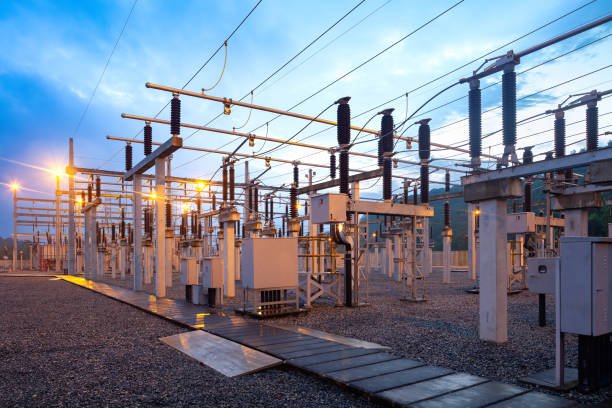
Power transformers are fundamental components of modern electrical systems, yet many buyers and end users only see them as large pieces of equipment that change voltage. Without understanding how a power transformer actually transfers electrical energy and why its construction matters, it can be difficult to evaluate transformer specifications, efficiency, reliability, or suitability for a particular application. Choosing the wrong transformer can lead to excessive losses, overheating, poor voltage regulation, premature insulation aging, and even serious system failures. Understanding the operating principle and main functions of a power transformer provides a practical foundation for making better technical and purchasing decisions.
A power transformer is a static electrical device that transfers AC electrical energy between circuits through electromagnetic induction while changing voltage and current levels. It normally consists of a magnetic core, primary winding, secondary winding, insulation system, and supporting components. When AC voltage is applied to the primary winding, it creates an alternating magnetic flux in the core, which induces a voltage in the secondary winding. By selecting an appropriate turns ratio, a power transformer can step voltage up or down while maintaining the same frequency and transferring power with relatively low losses.
From generation to transmission, distribution, and industrial consumption, transformers perform this voltage-conversion function throughout the electrical power system. The following outline explains how power transformers work, what their main components do, and which technical factors buyers should understand when selecting and evaluating transformer equipment.
What Is a Power Transformer and How Does a Power Transformer Work?
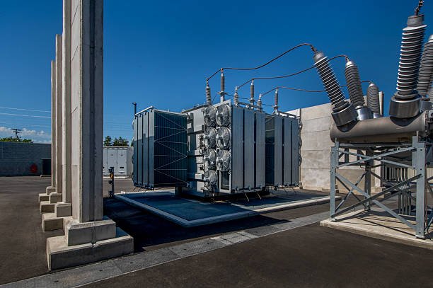
A power transformer is a critical component in modern electrical systems, but choosing or operating one without understanding its working principle can lead to incorrect voltage selection, poor efficiency, overheating, insulation stress, or unsuitable load performance. Buyers and engineers often see terms such as power transformer, step-up transformer, step-down transformer, transformer core, primary winding, secondary winding, voltage ratio, and electromagnetic induction, yet the relationship among these parts is not always obvious. Understanding how a power transformer works makes it much easier to evaluate transformer specifications, efficiency, capacity, cooling, insulation, and application suitability.
A power transformer is a static electrical device that transfers AC electrical energy from one circuit to another through electromagnetic induction while normally changing voltage and current levels without changing frequency. An AC voltage applied to the primary winding creates an alternating magnetic flux in the transformer core, which induces a voltage in the secondary winding. The turns ratio between the primary and secondary windings determines whether the transformer increases or decreases voltage, while the transformer's rated kVA/MVA capacity, insulation system, cooling design, and impedance determine how safely and efficiently it can operate under load.
The basic principle is simple, but a practical power transformer involves carefully engineered magnetic, electrical, thermal, mechanical, and insulation systems. Understanding each part helps buyers move from a textbook definition to a practical understanding of how a transformer performs in an actual power network.
A power transformer converts AC electricity into DC electricity.False
A conventional power transformer transfers AC electrical energy between circuits through electromagnetic induction and normally changes voltage and current while maintaining the same frequency. It does not inherently convert AC into DC.
What Is a Power Transformer?
A power transformer is a static electrical device designed to transfer electrical energy between two or more circuits by means of electromagnetic induction. Unlike motors and generators, a transformer has no normal rotating mechanical components. Its principal active electrical components are the magnetic core and windings, supported by an insulation system, enclosure or tank, cooling system, bushings, tap-changing equipment where required, and protection/accessory systems.
The primary purpose of a power transformer is to change the voltage level of alternating current. In an electrical grid, this function is essential because electricity is typically generated, transmitted, and distributed at different voltage levels.
For example, a generating station may produce electrical power at a medium voltage, while long-distance transmission requires a much higher voltage to reduce current for a given power level. Near the load center, another transformer can reduce the voltage to levels appropriate for substations, industrial facilities, or distribution networks.
The transformer therefore acts as an interface between different voltage levels.
| Transformer Function | Typical Purpose |
|---|---|
| Step-up | Increase voltage for transmission |
| Step-down | Reduce voltage for distribution or industrial use |
| Isolation | Electrically separate circuits while transferring energy |
| Voltage regulation | Maintain an appropriate output voltage under changing conditions |
| Grid interconnection | Connect electrical systems operating at different voltage levels |
The term power transformer is commonly associated with transformers used in generation, transmission, and major substation applications. The exact classification depends on the applicable standards, utility practice, voltage level, rating, and application.
What Are the Main Parts of a Power Transformer?
Although transformer designs vary significantly, most practical power transformers contain several major systems.
Magnetic Core
The transformer core provides a low-reluctance path for alternating magnetic flux. It is normally constructed from thin electrical-steel laminations rather than a single solid piece of steel. Laminating the core helps reduce eddy-current losses.
Grain-oriented electrical steel is widely used in power-transformer cores because its magnetic properties can be optimized for the direction of flux. Core construction, joint design, steel grade, clamping, and manufacturing quality all influence transformer losses and noise.
Primary Winding
The primary winding is connected to the input electrical circuit. When AC voltage is applied, alternating current produces alternating magnetic flux through the core.
Secondary Winding
The secondary winding is connected to the output circuit. The changing magnetic flux generated by the primary system induces voltage in the secondary winding.
The voltage relationship depends primarily on the relative number of turns.
Insulation System
The insulation system separates conductors from one another and from the grounded structure. Depending on the design, insulation can include solid insulation materials, insulating liquid, air, gas, or combinations of these.
Insulation design is critical because power transformers can operate at high voltages and must withstand normal operating stress as well as specified abnormal or transient conditions.
Tank and Cooling System
Oil-immersed transformers generally use a steel tank containing insulating liquid. Cooling radiators, fans, pumps, conservators, and other components may be used depending on transformer size and cooling method.
Dry-type transformers instead use air and solid insulation systems without the same oil-filled tank arrangement.
How Does a Power Transformer Work?
The operating principle can be understood in several sequential steps.
Step 1: AC voltage enters the primary winding.
An alternating voltage is applied to the primary winding. Because the voltage changes continuously with time, the resulting winding current and magnetic field also vary.
Step 2: The primary winding produces alternating magnetic flux.
The winding is arranged around or close to the transformer core. The alternating magnetomotive force establishes magnetic flux in the core.
Step 3: The core guides the magnetic flux.
The magnetic core provides an efficient path for the flux to link the primary and secondary windings.
Step 4: The changing flux induces secondary voltage.
According to Faraday's law of electromagnetic induction, changing magnetic flux through the secondary winding produces an induced electromotive force.
Step 5: The secondary circuit supplies the load.
When a load is connected to the secondary winding, secondary current flows. Energy is transferred from the primary electrical system to the secondary electrical system through the electromagnetic field.
The transformer therefore does not need a mechanical connection between its input and output circuits.
A simplified energy path is:
AC source
   ↓
Primary winding
   ↓
Alternating magnetic flux
   ↓
Transformer core
   ↓
Secondary winding
   ↓
AC load
This is the fundamental operating principle behind both small transformers and large substation power transformers.
How Does the Transformer Change Voltage?
The relationship between winding voltage and number of turns is commonly expressed as:
V₁ / V₂ ≈ N₁ / N₂
where:
- V₁ = primary voltage
- V₂ = secondary voltage
- N₁ = primary turns
- N₂ = secondary turns
If the secondary winding has fewer turns than the primary winding, the transformer operates as a step-down transformer.
If the secondary winding has more turns than the primary winding, it operates as a step-up transformer.
For example, if a transformer has 1,000 primary turns and 100 secondary turns, the ideal voltage ratio is 10:1. A primary voltage of 10,000 V would therefore correspond to approximately 1,000 V on the secondary under idealized conditions.
The actual terminal voltage will depend on loading, impedance, tap position, temperature, and transformer design.
What Happens to Current?
For an ideal transformer, power transferred from the primary to the secondary is approximately conserved:
V₁I₁ ≈ V₂I₂
This means that increasing voltage generally corresponds to decreasing current for the same transferred power, while decreasing voltage generally corresponds to increasing current.
This relationship explains why transformers are so valuable in power transmission.
For a simplified example:
| Parameter | Step-Up Example |
|---|---|
| Input voltage | 10 kV |
| Output voltage | 100 kV |
| Approximate voltage ratio | 1:10 |
| Input current at fixed power | Higher |
| Output current at fixed power | Approximately one-tenth |
| Frequency | Normally unchanged |
Reducing current is important because conductor losses are strongly related to current. For a resistive component, the loss is proportional to I²R, so reducing current can substantially reduce transmission losses.
Does a Transformer Change Frequency?
Under normal operation, a transformer does not change the frequency of the AC supply.
If a transformer receives 50 Hz AC, the secondary voltage is also nominally 50 Hz. Likewise, a 60 Hz input produces a 60 Hz secondary output.
| Input | Transformer Action | Output |
|---|---|---|
| 50 Hz AC | Changes voltage/current | 50 Hz AC |
| 60 Hz AC | Changes voltage/current | 60 Hz AC |
| DC | Conventional transformer action does not occur continuously | No normal steady-state transformer transfer |
This is why transformers are fundamentally AC electromagnetic devices. A steady DC voltage does not continually create the changing magnetic flux required for sustained transformer action.
Why Is the Transformer Core Important?
The core is more than a structural support. Its magnetic properties directly influence transformer performance.
A practical core must provide efficient magnetic coupling while controlling losses. Core losses generally include:
- Hysteresis loss
- Eddy-current loss
Hysteresis loss results from repeated magnetization and demagnetization of the magnetic material. Eddy currents are circulating currents induced within conductive core material by changing magnetic flux.
Using thin insulated laminations reduces the path available for eddy currents and therefore helps reduce associated losses.
Core design also influences:
- No-load loss
- Magnetizing current
- Temperature rise
- Acoustic noise
- Efficiency
- Flux density
- Short-circuit mechanical behavior
For this reason, buyers evaluating power transformers should not judge the magnetic system solely by its physical size. Core material, steel grade, thickness, joint design, flux density, and manufacturing quality are also important.
What Is the Difference Between Step-Up and Step-Down Transformers?
The fundamental electromagnetic principle is the same, but the winding ratio is different.
| Feature | Step-Up Transformer | Step-Down Transformer |
|---|---|---|
| Secondary turns | More than primary | Fewer than primary |
| Secondary voltage | Higher | Lower |
| Secondary current at equal power | Lower | Higher |
| Common application | Transmission | Distribution and industrial loads |
| Main objective | Raise voltage | Reduce voltage |
A transformer can therefore be designed for a particular voltage transformation according to the electrical network requirements.
What Determines Power Transformer Capacity?
Transformer capacity is normally expressed in VA, kVA, or MVA, rather than watts alone.
For larger power transformers, MVA is commonly used.
Capacity indicates the amount of apparent power the transformer is designed to transfer under specified operating conditions. However, capacity is not simply a measure of how much electricity can pass through the transformer without limitation.
The rated capacity depends on the transformer's:
- Winding conductor size
- Insulation system
- Cooling capability
- Temperature-rise limits
- Core and magnetic design
- Short-circuit withstand capability
- Ambient conditions
- Installation requirements
- Applicable standards
A transformer rated at 50 MVA and another rated at 100 MVA cannot be compared only by their physical dimensions. Their thermal, electrical, mechanical, and insulation systems are designed for different operating duties.
Why Are Cooling Systems Important?
When a transformer operates, part of the electrical energy is converted into heat through core and winding losses. If this heat is not removed effectively, winding and insulation temperatures can rise beyond acceptable limits.
Common cooling arrangements include:
- ONAN — Oil Natural, Air Natural
- ONAF — Oil Natural, Air Forced
- OFAF — Oil Forced, Air Forced
- OFWF — Oil Forced, Water Forced
- Dry-type air cooling arrangements
The appropriate cooling system depends on transformer rating, design, installation conditions, and required loading profile.
A buyer should therefore consider cooling capacity when evaluating transformer performance. A transformer that meets the nominal MVA rating under one specified condition may have different permissible loading characteristics under higher ambient temperatures or different cooling modes.
What Is Transformer Efficiency?
No real transformer is perfectly efficient because energy is lost in the core, windings, structural components, and auxiliary systems.
The main losses are generally divided into:
No-load or core losses: These occur whenever the transformer is energized and are associated primarily with the magnetic core.
Load or winding losses: These increase as transformer load current increases and include winding I²R losses as well as additional stray-load losses.
For a transformer operating continuously, even relatively small efficiency differences can have significant lifetime economic consequences.
This is why buyers should evaluate both:
- Transformer efficiency
- No-load loss
- Load loss
- Total loss at the expected loading profile
The most efficient transformer is not automatically the best transformer for every project, because procurement cost, loading pattern, reliability, maintenance, installation conditions, and regulatory requirements must also be considered.
What Happens When a Transformer Is Loaded?
When the secondary circuit is unloaded, the transformer still requires magnetizing current to establish magnetic flux. Once a load is connected, secondary current flows and produces its own magnetomotive force.
The transformer responds through the primary circuit so that energy can continue to be transferred while maintaining the magnetic balance of the core.
As load increases:
- Secondary current increases.
- Primary current increases correspondingly.
- Winding losses increase.
- Temperature rise increases.
- Voltage regulation becomes important.
- Cooling demand may increase.
This is why transformer specifications should include more than primary and secondary voltage. Rated capacity, impedance, cooling, temperature rise, insulation level, tap range, and loss performance are all important for practical application.
Why Does Transformer Impedance Matter?
Transformer impedance influences several important system characteristics, especially voltage regulation and fault current.
A higher transformer impedance can limit short-circuit current, but it may also produce greater voltage drop under load. A lower impedance can improve voltage regulation but may allow higher fault current.
Therefore, transformer impedance should be selected as part of the electrical system rather than treated as an isolated catalog value.
For parallel operation, impedance and related characteristics also become particularly important because transformers must be sufficiently compatible for appropriate load sharing.
How Do Tap Changers Affect Transformer Operation?
Some power transformers use tap-changing equipment to adjust the effective winding turns ratio.
There are two broad categories:
- Off-circuit tap changers: The transformer must normally be de-energized before the tap position is changed.
- On-load tap changers (OLTC): The tap position can be changed while the transformer remains energized and carrying load, using a dedicated switching mechanism.
Tap changing is commonly used to maintain an appropriate system voltage under changing network or load conditions.
For buyers, the important parameters include:
- Tap range
- Number of tap positions
- Tap step
- Tap-changer type
- Rated current
- Control system
- Maintenance requirements
Where Are Power Transformers Used?
Power transformers are used wherever electrical energy must be transferred between voltage levels or electrical systems.
Typical applications include:
- Power generation plants
- Transmission substations
- Distribution substations
- Industrial facilities
- Renewable-energy projects
- Data centers
- Mining facilities
- Petrochemical plants
- Large commercial facilities
- Utility interconnection systems
A step-down power transformer is particularly important when high-voltage electrical energy must be reduced to a voltage suitable for industrial equipment or downstream distribution.
What Are the Main Components of a Power Transformer and How Does Each Component Work?
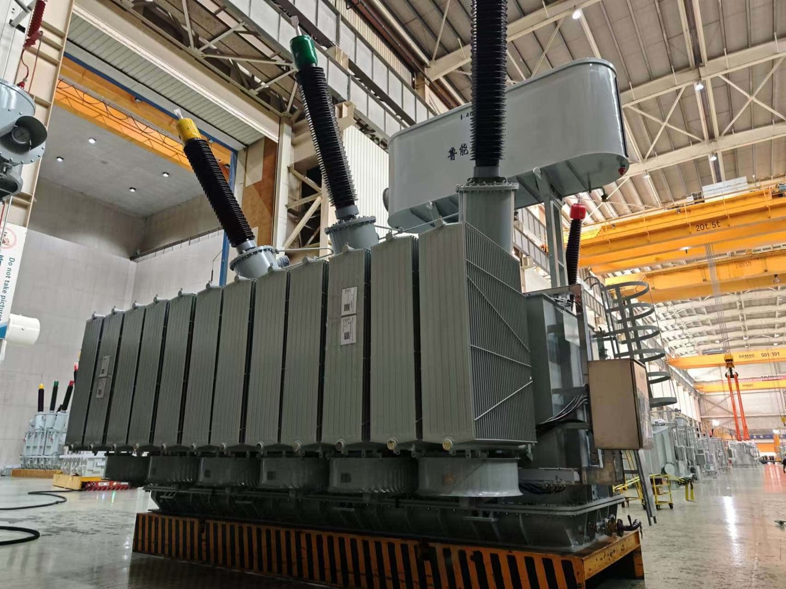
A power transformer may look like a large steel tank from the outside, but reliable operation depends on many interconnected components working together. If a buyer evaluates only the transformer rating, primary voltage, and secondary voltage, important risks can remain hidden. Poor core construction can increase losses, inadequate insulation can reduce dielectric reliability, insufficient cooling can accelerate aging, and unsuitable bushings or tap changers can create operational problems. Understanding the main components of a power transformer allows buyers, engineers, and maintenance teams to evaluate not only what each component does, but also why its design, material, manufacturing quality, and testing matter to the complete transformer system.
The main components of a power transformer include the magnetic core, high-voltage and low-voltage windings, insulation system, transformer tank, insulating liquid where applicable, bushings, cooling system, tap changer, conservator, breather, protection devices, pressure-relief equipment, temperature-monitoring devices, and mechanical clamping structures. The core provides the magnetic path, windings transfer electrical energy through electromagnetic induction, insulation separates energized parts, the tank provides mechanical and environmental protection, cooling removes heat, bushings provide insulated electrical connections, and control and protection components maintain safe and reliable operation.
The exact component arrangement depends on transformer type, rated power, voltage class, cooling method, insulation system, and application. A small dry-type transformer may have no oil tank or conservator, while a large oil-immersed substation transformer can contain a sophisticated network of cooling, protection, monitoring, and voltage-regulation equipment.
The transformer tank is the component that changes the primary voltage into the secondary voltage.False
Voltage transformation occurs through electromagnetic induction between the windings and magnetic flux in the core. The tank primarily provides mechanical protection and, in oil-immersed transformers, contains the insulating and cooling liquid.
What Is the Basic Structure of a Power Transformer?
A power transformer can be understood as several functional systems rather than one single machine. The active part normally consists of the magnetic core and windings, while the remaining components provide insulation, cooling, mechanical support, electrical connection, monitoring, protection, and voltage regulation.
A simplified structure is:
                 POWER TRANSFORMER
                        │
        ┌───────────────┼────────────────┐
        │               │                │
   Magnetic System  Electrical System  Support Systems
        │               │                │
       Core          HV/LV Windings    Tank & Clamping
        │               │                │
        └───────────────┼────────────────┘
                        │
              Insulation System
                        │
        ┌───────────────┼────────────────┐
        │               │                │
     Cooling       Connections       Protection
        │               │                │
   Radiators       Bushings          Relays/Sensors
   Fans/Pumps      Terminals         Pressure Devices
For buyers, this division is useful because it connects each physical component to a specific engineering function. It also helps identify the components that deserve the most attention during factory inspection and acceptance testing.
How Does the Transformer Core Work?
The magnetic core provides a controlled path for alternating magnetic flux generated by the windings. It is generally made from laminated electrical steel designed to provide favorable magnetic characteristics and low loss.
When alternating voltage is applied to the primary winding, alternating current establishes magnetic flux in the core. This flux links the secondary winding and produces an induced voltage.
The core therefore performs three important functions:
- Provides a low-reluctance magnetic path.
- Couples the primary and secondary windings magnetically.
- Helps control transformer magnetizing behavior and core losses.
The core is normally manufactured from thin steel laminations that are electrically insulated from one another. This construction reduces eddy-current circulation within the core.
Core manufacturing quality matters greatly. Poor stacking, excessive mechanical stress, unsuitable joints, damaged insulation between laminations, or incorrect clamping can increase losses, vibration, and acoustic noise.
| Core Characteristic | Why It Matters |
|---|---|
| Electrical-steel grade | Influences magnetic loss and flux performance |
| Lamination thickness | Affects eddy-current loss |
| Core joint quality | Influences magnetic flux distribution |
| Stacking accuracy | Affects loss, noise, and mechanical stability |
| Clamping pressure | Controls mechanical stability |
| Flux density | Influences saturation, losses, and noise |
| Core grounding | Controls unwanted circulating current paths |
For buyers, core-loss data should therefore be evaluated together with the manufacturer's core-material specifications and test records.
How Do High-Voltage and Low-Voltage Windings Work?
The windings are the primary electrical energy-transfer components.
The high-voltage winding is designed for the higher voltage circuit, while the low-voltage winding is designed for the lower voltage circuit. Depending on the transformer's function, one winding may be connected to the incoming system and the other to the outgoing system.
The winding turns ratio determines the basic voltage transformation.
       Primary winding              Secondary winding
       ┌─────────────┐              ┌─────────────┐
 AC →  │  N₁ turns   │ → Magnetic → │  N₂ turns   │ → AC load
       └─────────────┘     flux     └─────────────┘
                         through core
Winding construction becomes increasingly important as transformer ratings increase. Conductors must withstand normal current, thermal stress, electromagnetic forces during faults, and insulation stress.
Depending on the design, conductors may use copper or aluminum. Winding arrangements can include cylindrical, helical, disc, layer, or other configurations.
The manufacturer must carefully control:
- Conductor dimensions
- Number of turns
- Axial and radial dimensions
- Insulation spacing
- Winding tension
- Pressboard barriers
- Clamping pressure
- Cooling ducts
- Lead connections
A winding that meets the nominal electrical specification but has poor mechanical integrity may still present a serious long-term reliability risk.
What Is the Transformer Insulation System?
The insulation system prevents unwanted electrical breakdown between energized components and between energized components and ground.
In an oil-immersed power transformer, insulation may include combinations of:
- Kraft or cellulose-based paper
- Pressboard
- Transformer oil or other insulating liquid
- Insulating cylinders
- Spacers
- Barriers
- End insulation
- Lead insulation
The insulation system must withstand both normal operating voltage and transient electrical stresses.
Insulation performance is affected by:
- Moisture
- Temperature
- Aging
- Contamination
- Partial discharge
- Electrical stress
- Mechanical movement
- Insulating-liquid condition
Moisture is particularly important for cellulose insulation because it can significantly influence dielectric strength and accelerate thermal aging.
For this reason, transformer manufacturing normally requires strict control of drying and vacuum processing before final filling and sealing.
How Does the Transformer Tank Work?
The transformer tank forms the primary mechanical enclosure for many oil-immersed transformers.
Its functions include:
- Containing insulating liquid
- Protecting the active part
- Providing mechanical strength
- Supporting external components
- Limiting environmental exposure
- Maintaining pressure/vacuum integrity
The tank must withstand mechanical forces associated with transportation, operation, short-circuit events, and internal pressure conditions.
Large transformer tanks can also incorporate radiators, valves, lifting lugs, grounding terminals, inspection covers, and other attachments.
Tank quality should not be judged only by visual appearance. Buyers should consider weld quality, dimensional accuracy, leakage testing, coating quality, corrosion protection, and mechanical integrity.
What Role Does Transformer Oil Play?
In an oil-immersed transformer, the insulating liquid normally performs two major functions:
Electrical insulation: The liquid contributes to the dielectric insulation system between energized components.
Heat transfer: Heat generated in the core and windings is transferred to the liquid and then transported toward cooling surfaces.
The oil therefore forms part of the transformer's thermal and insulation systems.
Its condition can change during service because of oxidation, moisture absorption, contamination, thermal stress, and interaction with insulation materials. Consequently, transformer-liquid testing and maintenance can provide important information about transformer condition.
The exact insulating liquid should be selected according to the transformer design, applicable requirements, environmental considerations, and manufacturer specifications.
How Do Transformer Bushings Work?
Bushings provide insulated paths for electrical conductors to pass from the transformer interior through the grounded tank wall to the external electrical system.
A bushing must simultaneously provide:
- Electrical insulation
- Mechanical support
- Controlled electric-field distribution
- Environmental sealing
- Reliable connection to external conductors
Common bushing technologies include porcelain and composite external insulation with different internal insulation arrangements.
For higher-voltage applications, bushing design becomes particularly important because electric-field concentration must be controlled.
A bushing failure can be severe because it creates a direct interface between high-voltage electrical equipment and the surrounding grounded structure.
Buyers should therefore review bushing voltage rating, current rating, insulation level, creepage distance, technology, testing, and compatibility with the transformer design.
How Does the Cooling System Work?
Transformer losses generate heat. The cooling system removes this heat and keeps the transformer within its specified thermal operating limits.
Cooling may rely on natural circulation or forced circulation of air, oil, water, or combinations of these media.
Typical oil-immersed transformer cooling designations include:
| Cooling Method | Basic Principle |
|---|---|
| ONAN | Oil natural, air natural |
| ONAF | Oil natural, air forced |
| OFAF | Oil forced, air forced |
| OFWF | Oil forced, water forced |
The required cooling arrangement depends on transformer rating and operating conditions.
Radiators increase the surface area available for heat transfer. Fans can increase air movement across radiator surfaces. Pumps may circulate insulating liquid through dedicated cooling paths.
Cooling-system reliability is therefore part of transformer reliability. A transformer may have excellent electrical design but still suffer excessive temperature rise if its cooling system is improperly designed, poorly maintained, or inadequately controlled.
What Is a Tap Changer?
A tap changer changes the effective turns ratio of the transformer to regulate voltage.
There are two principal categories:
- Off-circuit tap changer
- On-load tap changer (OLTC)
An off-circuit tap changer normally requires the transformer to be de-energized before changing tap position.
An OLTC is designed to change taps while the transformer is energized and carrying load.
A tap changer can include a diverter switch, selector mechanism, drive mechanism, control cabinet, and monitoring equipment.
For buyers, relevant specifications include:
- Tap range
- Number of positions
- Tap step
- Rated current
- Insulation level
- Switching duty
- Control method
- Maintenance requirements
For voltage-sensitive industrial and utility applications, tap-changer selection can be a major part of transformer system design.
How Does the Conservator Work?
Many oil-immersed transformers use a conservator tank above the main tank.
Transformer insulating liquid expands as its temperature rises and contracts as it cools. The conservator provides space for this volume change while helping maintain the desired oil level in the main tank.
A typical arrangement is:
             Conservator
          ┌───────────────┐
          │  Oil reserve  │
          └───────┬───────┘
                  │
              Oil pipe
                  │
          ┌───────▼───────┐
          │ Main tank     │
          │ Core/Windings │
          └───────────────┘
The conservator is normally associated with a breather system, which manages air entering and leaving the conservator as oil volume changes.
What Does the Breather Do?
A transformer breather helps prevent moisture-laden atmospheric air from entering directly into the conservator as the oil contracts.
Traditional breathers commonly use silica gel as a moisture-absorbing medium.
The principle is straightforward:
Oil temperature rises
        ↓
Oil expands
        ↓
Air moves outward

Oil temperature falls
        ↓
Oil contracts
        ↓
Air enters through breather
        ↓
Moisture is reduced before entering system
The breather therefore supports insulation-liquid and insulation-system reliability.
Buyers should check the breather design, silica-gel arrangement, sealing condition, and maintenance provisions where applicable.
What Protection Devices Are Used?
Power transformers can use several protection and monitoring devices.
Depending on transformer size and design, these may include:
- Buchholz relay
- Pressure-relief device
- Oil-temperature indicator
- Winding-temperature indicator
- Sudden-pressure relay
- Oil-level indicator
- Gas monitoring
- Cooling-system alarms
- OLTC protection
- Marshalling cabinet monitoring
A Buchholz relay, for example, is commonly associated with conservator-type oil-filled transformers. It can detect gas accumulation and oil-flow disturbances associated with certain internal faults.
A pressure-relief device provides a controlled means of relieving excessive internal pressure.
Temperature indicators monitor thermal conditions and can provide alarms or control signals for cooling equipment.
These devices do not make the transformer more powerful; they make its operating condition more observable and help detect abnormal conditions before they develop into more serious failures.
What Is the Purpose of the Transformer Clamping Structure?
The clamping structure holds the core and windings mechanically in position.
This is especially important during short-circuit events because transformer windings can experience very large electromagnetic forces.
The clamping system must maintain sufficient mechanical stability without causing damaging stress concentrations.
Important considerations include:
- Axial compression
- Radial support
- Winding bracing
- Core clamping
- Transportation stability
- Short-circuit mechanical strength
For large power transformers, mechanical design is therefore as important as electrical design.
Why Are Grounding Connections Important?
Transformer grounding provides controlled electrical reference paths for the tank, core-related structures, and other components that must be bonded to ground.
Proper grounding helps:
- Control touch voltage
- Provide fault-current paths
- Reduce unwanted electrical potential
- Support protection-system operation
- Improve personnel safety
Grounding arrangements must be coordinated with the electrical installation rather than considered independently from the substation grounding system.
How Do These Components Work Together?
The most important point is that no major transformer component operates completely independently.
Consider the energy-transfer process:
Electrical input
      ↓
Primary winding
      ↓
Magnetic flux
      ↓
Core
      ↓
Secondary winding
      ↓
Electrical output
At the same time:
Core + Windings
      ↓
Generate heat
      ↓
Insulating liquid / insulation
      ↓
Radiators
      ↓
Fans or natural air
      ↓
Heat released to environment
And the protection system continuously monitors the operating condition:
Temperature ─┐
Oil level ───┤
Pressure ────┼──→ Monitoring / Protection
Gas ─────────┤
OLTC ────────┘
                    ↓
             Alarm / Trip / Control
This interaction explains why transformer procurement should evaluate the complete system, not isolated components.
Which Transformer Components Should Buyers Inspect Most Carefully?
Not every component carries the same risk for every transformer. However, buyers should pay particular attention to the active part and components that directly affect electrical insulation, thermal performance, voltage regulation, and protection.
| Component | Main Function | Key Buyer Checks |
|---|---|---|
| Magnetic core | Provides magnetic flux path | Core material, losses, construction |
| HV winding | Handles high-voltage circuit | Insulation, dimensions, mechanical strength |
| LV winding | Handles lower-voltage circuit | Current capacity, cooling, insulation |
| Insulation | Prevents electrical breakdown | Drying, dielectric performance |
| Tank | Encloses active part | Welds, leakage, coating, strength |
| Insulating liquid | Insulation and heat transfer | Quality, cleanliness, test results |
| Bushings | Insulated external connection | Rating, insulation, testing |
| Radiators | Dissipate heat | Size, construction, leakage protection |
| Fans/pumps | Increase cooling capacity | Reliability, controls, redundancy |
| Tap changer | Adjusts voltage ratio | Range, current, switching system |
| Conservator | Accommodates oil expansion | Capacity, sealing, oil-level system |
| Breather | Controls moisture in incoming air | Design and maintenance |
| Protection devices | Detect abnormal conditions | Function, alarms, testing |
| Clamping structure | Provides mechanical stability | Short-circuit and transport strength |
| Grounding system | Provides controlled electrical path | Bonding and continuity |
What Should Buyers Ask the Manufacturer?
A professional supplier should be able to explain not only what components are installed, but also why they were selected for the particular transformer.
Useful questions include:
- What core material and construction method are used?
- What winding configuration is used?
- How is winding mechanical strength verified?
- What insulation system is used?
- How is moisture removed before oil filling?
- What cooling method is specified?
- What happens if a cooling fan or pump fails?
- What bushing technology and ratings are used?
- Is an OLTC required, and what is its tap range?
- How is internal pressure managed?
- Which protection devices are installed?
- What temperature and oil-level monitoring is provided?
- How is the active part mechanically clamped?
- What routine tests are performed before shipment?
- Which component suppliers are considered critical?
The manufacturer's answers should correspond with the transformer drawings, bill of materials, technical specification, factory test records, and quality-control procedures.
Why Does Component Quality Affect Transformer Service Life?
Transformer service life is determined by the combined performance of its electrical, thermal, insulation, and mechanical systems.
A high-quality core can reduce losses. Good winding construction can improve short-circuit resistance. Proper drying can protect the insulation system. Effective cooling can control temperature rise. Reliable bushings can reduce external insulation risk. Accurate protection systems can identify abnormal conditions early.
This means that a transformer should be evaluated as an integrated system:
Core + Windings + Insulation + Cooling + Mechanical Structure + Connections + Protection = Transformer Reliability
A weakness in one subsystem can affect the performance of the others.
For example, inadequate cooling increases winding temperature. Higher temperature accelerates insulation aging. Insulation aging reduces dielectric reliability. Therefore, cooling-system performance indirectly influences insulation life.
Similarly, poor mechanical clamping can allow winding movement during a fault, potentially damaging insulation and conductors.
Below is the article in the same professional, technical, buyer-oriented format, with electromagnetic induction explained from both the physical principle and practical transformer-design perspective.
How Does Electromagnetic Induction Make a Power Transformer Work?
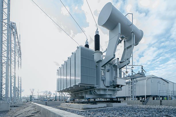
A power transformer may appear to be a simple combination of a magnetic core and two windings, but its operation depends on a precise electromagnetic process. Without electromagnetic induction, a transformer cannot transfer AC energy from the primary circuit to the secondary circuit. Misunderstanding this principle can lead to incorrect assumptions about voltage ratio, winding design, core selection, frequency, losses, and transformer loading. For buyers and engineers, understanding how electromagnetic induction makes a power transformer work is therefore essential for evaluating transformer design, efficiency, insulation, winding construction, and application suitability.
Electromagnetic induction makes a power transformer work by using an alternating current in the primary winding to create changing magnetic flux in the transformer core. That changing flux links the secondary winding and induces an AC voltage in it according to Faraday's law. The number of turns on the primary and secondary windings determines the basic voltage ratio, while the magnetic core provides the flux path and the windings, insulation, cooling system, and mechanical structure allow this electromagnetic energy transfer to occur safely and efficiently.
The principle can be understood in a few simple steps, but practical power transformers add significant engineering detail. The following explanation connects the physics of induction with the components and performance characteristics that buyers should actually evaluate.
A transformer transfers electrical energy from the primary winding to the secondary winding through a direct electrical connection between the two windings.False
In a conventional transformer, energy is transferred primarily through magnetic coupling. The primary and secondary circuits are electrically isolated in typical isolation-transformer construction while being magnetically linked through changing flux in the core.
How Does Faraday's Law Explain Transformer Operation?
The fundamental physical law behind transformer action is Faraday's law of electromagnetic induction.
For a winding with multiple turns, the induced voltage depends on how quickly the magnetic flux linkage changes. Conceptually:
Induced voltage ∝ number of turns × rate of change of magnetic flux
This relationship explains several important transformer characteristics.
If the magnetic flux changes more rapidly, the induced voltage increases.
If the winding contains more turns, the induced voltage increases.
If the magnetic flux does not change, there is no sustained induced voltage.
For a sinusoidal AC supply, the magnetic flux also varies approximately sinusoidally under normal transformer operation. This continuously changing flux provides the mechanism through which the primary and secondary circuits remain magnetically coupled.
What Happens in the Primary Winding?
The process begins when an AC voltage is applied to the primary winding.
The applied voltage causes current to flow in the primary winding. This current produces magnetomotive force, which establishes magnetic flux in the transformer core.
The primary winding therefore performs two closely related functions:
- It receives electrical energy from the source.
- It establishes the alternating magnetic field needed for induction.
The primary winding must be carefully designed because it experiences electrical, thermal, and mechanical stresses.
Its design depends on:
- Rated voltage
- Rated current
- Number of turns
- Conductor material
- Conductor cross-sectional area
- Insulation system
- Winding geometry
- Cooling requirements
- Short-circuit mechanical forces
The relationship between voltage, frequency, number of turns, and magnetic flux is especially important. For a given core, frequency, and voltage, an inappropriate number of turns can drive the core toward excessive flux density.
Why Does the Transformer Core Matter?
The primary winding does not simply radiate magnetic energy into open space. The magnetic core provides a controlled, low-reluctance path for the magnetic flux.
This improves magnetic coupling between the primary and secondary windings.
A simplified magnetic circuit is:
       Primary                    Secondary
      winding                    winding
    ┌─────────┐                ┌─────────┐
    │ ((((((((│                │)))))))) │
    └────┬────┘                └────┬────┘
         │                          │
         └────── Magnetic Core ─────┘
                 ↕  ↕  ↕
              Alternating Flux
In practical power transformers, the core is generally constructed from electrical steel laminations. The laminations help reduce eddy-current losses.
Core design affects:
- No-load loss
- Magnetizing current
- Flux density
- Efficiency
- Noise
- Temperature rise
- Magnetic coupling
This is why buyers should evaluate transformer core material and manufacturing quality rather than considering the core simply as a passive piece of steel.
How Does Magnetic Flux Reach the Secondary Winding?
The primary and secondary windings are positioned so that a substantial portion of the alternating magnetic flux generated by the primary links the secondary.
When the flux changes, it produces an induced voltage in every secondary turn.
If the secondary winding is open-circuit, voltage can still be measured at its terminals, but essentially no useful load current flows.
Once a load is connected, the induced voltage drives current through the secondary circuit.
The complete sequence becomes:
Primary AC voltage
        ↓
Primary current
        ↓
Alternating magnetic flux
        ↓
Flux linkage with secondary
        ↓
Induced secondary voltage
        ↓
Secondary load current
        ↓
Electrical power delivered to load
This is the essential energy-transfer mechanism.
Why Does the Number of Turns Determine Voltage?
Each winding contains a specific number of turns around the magnetic core.
The basic ideal relationship is:
V₁ / V₂ ≈ N₁ / N₂
where:
- V₁ = primary voltage
- V₂ = secondary voltage
- N₁ = primary turns
- N₂ = secondary turns
Suppose a transformer has 2,000 primary turns and 200 secondary turns. Its approximate turns ratio is 10:1.
If 10,000 V is applied to the primary, the ideal secondary voltage is approximately 1,000 V.
This is the basis of a step-down transformer.
If the secondary has more turns than the primary, the voltage can instead be increased, creating a step-up transformer.
| Winding Relationship | Voltage Effect | Transformer Type |
|---|---|---|
| N₂ < N₁ | Secondary voltage lower | Step-down |
| N₂ > N₁ | Secondary voltage higher | Step-up |
| N₂ ≈ N₁ | Similar voltage | Approximately 1:1 |
| More secondary turns | Higher induced voltage per winding | Step-up configuration |
| Fewer secondary turns | Lower induced voltage | Step-down configuration |
The actual terminal voltage also depends on impedance, winding resistance, loading, tap position, and transformer design.
Does Electromagnetic Induction Change Frequency?
No. A conventional transformer normally changes voltage and current, but it does not change the frequency.
A 50 Hz input produces a 50 Hz output, while a 60 Hz input produces a 60 Hz output.
| Input Frequency | Transformer Action | Output Frequency |
|---|---|---|
| 50 Hz | Voltage transformation | 50 Hz |
| 60 Hz | Voltage transformation | 60 Hz |
| Steady DC | No continuous normal induction | No continuous normal transformer output |
This distinction is important when selecting a transformer because the magnetic core and winding design must be appropriate for the specified operating frequency.
Why Is Frequency Important to Magnetic Flux?
Transformer voltage, frequency, number of turns, and magnetic flux are closely connected.
For a sinusoidal excitation, a simplified transformer relationship is:
V ∝ f × N × Φ
where:
- V represents applied winding voltage,
- f represents frequency,
- N represents winding turns,
- Φ represents magnetic flux.
This relationship explains why transformer designers cannot arbitrarily increase voltage or reduce frequency without considering core flux.
If voltage increases while frequency remains constant, magnetic flux tends to increase.
If frequency decreases while voltage remains constant, magnetic flux also tends to increase.
Excessive flux can push the core toward saturation, causing high magnetizing current, increased losses, distortion, noise, and potentially overheating.
For buyers, the specified voltage-frequency combination must therefore match the transformer's design.
How Is Energy Transferred Without a Direct Electrical Connection?
In a typical transformer, the primary and secondary windings are electrically separated by insulation.
Yet energy can still be transferred because the magnetic field provides the coupling mechanism.
This can be compared with a mechanical system:
Primary circuit
     │
     │ Electrical energy
     ↓
Primary winding
     │
     │ Magnetic field
     ↓
Transformer core
     │
     │ Magnetic coupling
     ↓
Secondary winding
     │
     │ Electrical energy
     ↓
Secondary circuit
The absence of a direct electrical connection between the two circuits is particularly valuable for isolation and voltage transformation.
The insulation system must maintain adequate separation while controlling electric-field stress.
What Happens When a Secondary Load Is Connected?
When the secondary circuit is open, the primary mainly supplies the magnetizing current and the transformer's no-load losses.
When a load is connected to the secondary, secondary current flows.
That current creates its own magnetomotive force. The primary system responds by drawing additional current from the source so that the magnetic system remains approximately balanced.
This is why transformer primary current increases as secondary load increases.
For an ideal transformer:
V₁I₁ ≈ V₂I₂
Therefore, if the transformer steps voltage down by a factor of 10, the current capability on the lower-voltage side is approximately increased by a corresponding factor for the same transferred power.
Why Are Real Transformers Less Than 100% Efficient?
Electromagnetic induction itself is highly effective, but real transformers have losses.
The most important categories include:
Core losses: Associated mainly with hysteresis and eddy currents in the magnetic core.
Winding losses: Mainly resistive losses caused by current flowing through winding conductors.
Stray losses: Additional losses caused by leakage flux inducing currents in structural and conductive components.
Auxiliary losses: Power consumed by fans, pumps, controls, and monitoring equipment where applicable.
A practical transformer therefore satisfies:
Output power < Input power
The difference appears primarily as heat and other losses.
This is why cooling and thermal design are essential parts of transformer engineering.
What Is Leakage Flux?
Not all magnetic flux produced by the primary winding links perfectly with the secondary winding.
Some flux follows paths that do not fully couple the two windings. This is called leakage flux.
Leakage flux contributes to transformer leakage reactance and therefore affects impedance and voltage regulation.
A simplified concept is:
Total primary flux
├── Useful mutual flux → links both windings
└── Leakage flux → does not fully link both windings
Transformer designers carefully control winding geometry and spacing to achieve the required impedance characteristics.
This is particularly important in power transformers because impedance influences fault-current behavior and voltage regulation.
How Does Induction Relate to Transformer Impedance?
Transformer impedance is closely connected with leakage reactance and winding resistance.
When current flows through the transformer, its internal impedance causes voltage drop.
As load increases, this can cause the secondary terminal voltage to differ from its no-load value.
Therefore, a transformer cannot be evaluated only by its theoretical turns ratio.
A buyer should also examine:
- Percent impedance
- Winding resistance
- Load loss
- Voltage regulation
- Short-circuit withstand capability
For utility and industrial applications, these parameters influence how the transformer behaves as part of the larger electrical network.
What Happens If the Core Saturates?
Core saturation occurs when the magnetic material approaches a region where additional magnetizing force produces only a relatively small increase in magnetic flux.
In a transformer, excessive flux density can cause:
- Sharp increases in magnetizing current
- Increased core losses
- Higher temperature
- Greater acoustic noise
- Current waveform distortion
- Increased electrical stress
Potential causes include:
- Excessive applied voltage
- Incorrect operating frequency
- Insufficient primary turns
- Incorrect transformer design
- Certain transient conditions
For this reason, transformer manufacturers carefully establish the magnetic operating point during design.
Why Is Insulation Important to Electromagnetic Induction?
The induced voltage is only useful if the transformer can safely withstand the electrical stresses associated with it.
The primary and secondary windings may operate at substantially different voltage levels. Insulation must prevent unwanted electrical breakdown between:
- Turns
- Winding sections
- Primary and secondary windings
- Windings and core
- Windings and tank
- Internal conductors and grounded structures
In oil-immersed transformers, solid insulation and insulating liquid work together.
Moisture control is especially important because water can adversely affect cellulose insulation and dielectric performance.
Therefore, transformer drying and vacuum processing are essential manufacturing steps.
How Do Cooling and Induction Work Together?
Electromagnetic induction transfers electrical energy, but the process is not lossless.
Core and winding losses produce heat.
The thermal pathway in an oil-immersed transformer can be simplified as:
Electrical loading
       ↓
Core + winding losses
       ↓
Heat generation
       ↓
Insulating liquid / solid insulation
       ↓
Radiators
       ↓
Natural or forced air
       ↓
Environment
If the cooling system cannot remove heat at the required rate, temperature rises.
Higher operating temperature can accelerate insulation aging, which is why cooling performance is an important part of transformer service life.
Why Should Buyers Understand Induction When Purchasing a Transformer?
Understanding electromagnetic induction helps buyers recognize why certain specifications cannot be considered independently.
For example, a buyer may ask only for a 20 MVA, 69/13.8 kV transformer. But the manufacturer must translate these requirements into:
- Core dimensions
- Number of winding turns
- Conductor dimensions
- Insulation distances
- Flux density
- Impedance
- Cooling capacity
- Temperature-rise limits
- Mechanical support
- Testing requirements
The buyer should therefore evaluate whether the manufacturer can demonstrate sound engineering behind the electromagnetic design.
Useful questions include:
- What core material is used?
- How is operating flux density determined?
- How are winding turns calculated?
- How is leakage reactance controlled?
- How are winding mechanical forces addressed?
- How is insulation coordinated with voltage level?
- How are core and load losses verified?
- How is temperature rise tested?
- How is the transformer protected against excessive pressure or temperature?
- Which routine and specified tests verify the final design?
What Are the Most Important Induction-Related Quality Checks?
A professional factory evaluation should connect electromagnetic design with measurable test results.
| Check | What It Helps Verify |
|---|---|
| Turns-ratio test | Confirms winding ratio |
| Winding-resistance test | Identifies winding electrical characteristics |
| No-load loss test | Evaluates core-loss performance |
| Load-loss test | Evaluates winding and additional losses |
| Insulation tests | Verify dielectric performance |
| Temperature-rise test where specified | Evaluates thermal design |
| Impedance measurement | Confirms network characteristics |
| Routine electrical tests | Verify manufacturing consistency |
| Visual/internal inspection | Checks construction quality |
These tests do not all directly “measure electromagnetic induction,” but together they confirm whether the physical transformer has been manufactured consistently with its electromagnetic design.
How Does the Turns Ratio Determine How a Power Transformer Works?
A power transformer can fail to deliver the required voltage even when its core, windings, insulation, and cooling system are otherwise well designed if the turns ratio is selected incorrectly. An unsuitable ratio can produce excessive secondary voltage, insufficient voltage, unnecessary current, overheating, poor equipment performance, or even insulation stress. For buyers and engineers, understanding the turns ratio is therefore essential because it directly connects the transformer's winding design with its intended voltage conversion. The good news is that the principle is straightforward: by comparing the number of turns on the primary and secondary windings, engineers can predict the approximate voltage relationship and then select a practical transformer design around the required load, frequency, insulation level, and operating conditions.
The turns ratio determines the basic voltage conversion of a power transformer: the secondary-to-primary voltage ratio is approximately equal to the secondary-to-primary turns ratio. Therefore, a transformer with fewer secondary turns than primary turns is a step-down transformer, while one with more secondary turns is a step-up transformer. For example, a 10:1 primary-to-secondary turns ratio ideally converts 10 kV on the primary into approximately 1 kV on the secondary, subject to winding resistance, leakage reactance, regulation, and other losses.
To understand why this relationship works, it is useful to start with electromagnetic induction and then connect the turns ratio to practical transformer design. The turns ratio is not simply a number printed on a nameplate; it is a consequence of how the windings interact with the magnetic flux produced by the transformer core. Once this relationship is clear, voltage selection, current capability, impedance transformation, regulation, insulation design, and transformer testing become much easier to understand.
[Featured Image Placeholder: A professional cutaway power transformer showing primary and secondary windings with different numbers of turns, magnetic flux arrows through the laminated core, and labeled input/output voltages.]
AI image prompt: [Subject] a cutaway industrial power transformer showing primary and secondary windings with clearly different numbers of turns, magnetic flux traveling through a laminated steel core, labeled high-voltage and low-voltage terminals, [Style/Medium] photorealistic engineering visualization with precise technical illustration details, [Details/Attributes] visible copper windings, laminated core construction, realistic insulation, clear winding arrangement, subtle voltage and turns-ratio annotations, clean cross-sectional presentation, [Environment/Setting] modern electrical engineering laboratory or transformer manufacturing inspection area, [Mood/Atmosphere] precise, professional, educational, technically trustworthy, [Lighting] bright controlled industrial lighting with soft highlights and clear visibility of internal components.
A transformer with more turns on the secondary winding than on the primary winding normally produces a higher secondary voltage.True
For an ideal transformer, the voltage ratio is proportional to the turns ratio, so increasing the secondary-to-primary turns ratio produces a higher secondary voltage.
How Does the Turns Ratio Control Voltage?
The simplest transformer relationship is that the voltage ratio approximately follows the turns ratio. If the secondary winding has half as many turns as the primary winding, its induced voltage is approximately half the primary voltage under ideal conditions. If the secondary has twice as many turns, its voltage is approximately twice the primary voltage. This proportional relationship arises because each turn experiences the changing magnetic flux generated in the core. In a simplified transformer, the induced voltage per turn is essentially the same for both windings because both windings are linked by the same core flux. Multiplying the voltage-per-turn value by the number of turns gives the winding voltage. This makes the turns ratio an extremely powerful design parameter. Consider a transformer with a 6,000 V primary and a 600 V secondary. The primary has ten times the turns of the secondary, so the nominal voltage conversion is approximately 10:1. If the same core and winding technology were rearranged to provide 6,000 V primary and 12,000 V secondary, the secondary would require approximately twice the number of turns relative to the primary, assuming the same fundamental frequency and magnetic design constraints. However, engineers must not interpret the ideal relationship as an exact guarantee of terminal voltage. Real transformers have winding resistance, leakage reactance, magnetizing current, core losses, and other effects. Under load, the voltage drop across the transformer's internal impedance changes the delivered voltage. This is why transformer datasheets distinguish rated voltage from actual loaded voltage and specify voltage regulation. The distinction becomes especially important in distribution and industrial applications where long cable runs, motor starting currents, variable loads, or sensitive electronic equipment can cause voltage deviations. A correct turns ratio gives the transformer the right voltage conversion foundation, but the winding impedance and tap configuration determine how well that voltage is maintained. During factory testing, manufacturers verify winding ratios and polarity, while other tests evaluate losses, impedance, dielectric performance, and temperature-related behavior. Buyers should therefore avoid selecting a transformer based solely on a simple turns-ratio calculation when the application has demanding voltage-regulation requirements.
| Primary Turns | Secondary Turns | Primary-to-Secondary Ratio | Ideal Voltage Relationship | Transformer Type |
|---|---|---|---|---|
| 1,000 | 100 | 10:1 | Secondary ≈ 10% of primary | Step-down |
| 1,000 | 500 | 2:1 | Secondary ≈ 50% of primary | Step-down |
| 1,000 | 1,000 | 1:1 | Secondary ≈ primary | Isolation / voltage matching |
| 1,000 | 2,000 | 1:2 | Secondary ≈ 2× primary | Step-up |
| 1,000 | 10,000 | 1:10 | Secondary ≈ 10× primary | Step-up |
How Does the Turns Ratio Affect Current?
The turns ratio also determines the inverse relationship between winding currents in an ideal transformer. When the transformer steps voltage down, the available secondary current increases correspondingly for approximately the same power, ignoring losses. This is a direct consequence of conservation of energy: a transformer does not create electrical power merely by changing voltage. If the voltage is reduced, the current capability on the low-voltage side must increase for the transformer to transfer the same approximate power. For example, an ideal transformer receiving 10 kW at 10 kV draws approximately 1 A on its high-voltage side. If the transformer delivers that power at 1 kV, the secondary current is approximately 10 A. In practice, the input power must be slightly higher than the output power because the transformer has core loss, winding loss, stray loss, and other losses. This inverse current relationship has major consequences for conductor selection and thermal design. High-voltage windings generally use fewer amperes and can therefore use relatively smaller conductor cross-sections than the low-voltage winding of the same power rating, although insulation requirements on the high-voltage side are more demanding. Low-voltage windings often require substantial copper or aluminum cross-sectional area because they carry high current. The relationship also explains why transformer manufacturers cannot determine winding construction from voltage ratio alone. A transformer may have the correct turns ratio but still be unsuitable if its conductor size, cooling system, short-circuit strength, or insulation system cannot withstand the specified current and operating conditions. In addition, the current is affected by transformer impedance and the connected load. A low-voltage winding connected to a high-power motor, rectifier, or industrial heating load can experience substantial current and electromagnetic forces during abnormal events. Manufacturers therefore design winding clamping, conductor arrangement, insulation, and mechanical support as an integrated system. From a buyer's perspective, the practical lesson is clear: turns ratio determines the nominal voltage relationship, but rated kVA or MVA determines the power-transfer scale, and the resulting winding currents drive much of the conductor and thermal design.
How Does a Step-Up or Step-Down Transformer Use Turns?
A step-down transformer uses more primary turns than secondary turns. This configuration reduces voltage and increases secondary current capability for a given power level. It is common when a higher transmission or distribution voltage must be reduced to a lower voltage suitable for industrial equipment, building services, control systems, or other loads. A step-up transformer uses more secondary turns than primary turns and increases voltage while reducing current for approximately constant transferred power. Step-up transformers are especially important in power-generation and transmission systems because transmitting a given amount of power at higher voltage reduces the current required for the same power level. Lower current can reduce resistive losses in transmission conductors, although the complete system design also depends on conductor resistance, insulation requirements, system voltage, network configuration, and operating conditions. A 1:10 turns ratio does not mean the transformer is automatically suitable for every application involving a tenfold voltage increase. The core must be appropriate for the operating frequency and flux density, the insulation system must withstand the resulting voltage stresses, and the windings must have adequate current and thermal capacity. Similarly, a 10:1 step-down ratio does not establish the transformer's kVA capacity. Two transformers can have the same nominal voltage ratio but completely different power ratings, dimensions, cooling systems, impedance values, and short-circuit withstand capabilities. This distinction is particularly important when purchasing power transformers because voltage conversion and power capacity are separate specification dimensions. Buyers should define primary rated voltage, secondary rated voltage, frequency, rated capacity, phase configuration, connection group, impedance, insulation level, cooling method, tap range, and environmental conditions together. The turns ratio should then be understood as the winding-level mechanism that creates the specified voltage conversion. This approach prevents a common procurement mistake: selecting a transformer because its input and output voltages appear correct while overlooking the load current, thermal duty, fault duty, and insulation requirements.
Why Is the Turns Ratio Not Exactly Equal to the Measured Voltage Ratio Under Load?
In an ideal transformer, the voltage ratio and turns ratio are directly proportional. In a real power transformer, however, the measured terminal-voltage ratio can differ from the ideal value because the transformer has internal impedance. Winding resistance produces an (I^2R) voltage drop and heat, while leakage reactance produces a voltage drop that depends on load current and power factor. These effects become more visible as transformer loading increases. For a resistive load, the voltage drop may be dominated by the transformer's effective resistance and leakage reactance combination. For inductive loads such as motors, the phase relationship between current and voltage changes the effect of leakage reactance on terminal voltage. Consequently, a transformer that measures close to its nominal turns ratio at no load may deliver a somewhat different voltage at full load. This is the engineering reason for specifying voltage regulation. Tap changers provide another way to manage the effective voltage relationship. By changing the number of active winding turns, a tap changer can adjust the effective turns ratio to compensate for system-voltage variations or expected load-related voltage changes. Depending on transformer design, taps may be located on a winding selected to balance insulation, current, mechanical, and switching requirements. On-load tap changers can change the effective ratio while the transformer remains energized, whereas off-circuit tap arrangements generally require the transformer to be de-energized before the tap position is changed. Buyers should therefore identify whether the project requires fixed ratio, off-circuit taps, or on-load voltage regulation. A manufacturer can then select an appropriate winding arrangement, tap range, and switching technology. During commissioning and maintenance, turns-ratio testing can reveal winding problems such as incorrect connections, shorted turns, winding deformation, or tap-changer issues. The test result should be interpreted against the transformer's design data and applicable test procedure rather than against an oversimplified assumption that every measured ratio must be exactly identical to a theoretical value under every condition.
What Happens if the Turns Ratio Is Incorrect?
An incorrect turns ratio can cause both performance and reliability problems. If the secondary voltage is too high, connected equipment may experience excessive voltage stress, increased losses, overheating, abnormal motor behavior, or premature component failure. If the secondary voltage is too low, motors may draw increased current under certain operating conditions, equipment may fail to reach its intended operating point, and control or electronic systems may malfunction. The consequences depend strongly on the type of load and the magnitude of the voltage deviation. Incorrect ratio can also create problems when transformers operate in parallel. Parallel transformers must have compatible voltage ratios, phase relationships, impedance characteristics, and other relevant parameters. A mismatch in ratio can produce circulating current between transformers even when the external load is relatively small. Such current increases losses and heating and can reduce the useful capacity of the transformer group. For this reason, transformer ratio verification is an important factory and field-testing consideration. Manufacturers commonly perform ratio and polarity-related tests to confirm that the winding configuration matches the specified design. Buyers should review test reports and ensure that the tested transformer configuration corresponds to the nameplate and project requirements, including tap positions where applicable. It is also important to recognize that an incorrect ratio may result from more than a manufacturing error. Tap position, connection configuration, maintenance work, incorrect reconnection, or damaged winding sections can alter the effective ratio. A professional troubleshooting process therefore compares measured results with the transformer's design documentation and evaluates all tap positions or relevant phases rather than drawing a conclusion from a single measurement. For critical installations, ratio testing can be combined with winding-resistance measurement, insulation tests, excitation-current measurements, and other diagnostic methods to build a more complete picture of transformer condition.
| Design / Operating Factor | Relationship to Turns Ratio | Practical Consequence |
|---|---|---|
| Primary voltage | Sets the flux and required primary winding design | Determines primary insulation and winding requirements |
| Secondary voltage | Controlled fundamentally by turns ratio | Determines load-side operating voltage |
| Winding current | Approximately inverse to voltage ratio for equal power | Determines conductor size and thermal duty |
| Rated kVA/MVA | Independent of ratio | Determines power-transfer capacity |
| Leakage reactance | Does not change the basic turns ratio but affects loaded voltage | Influences voltage regulation and fault current |
| Tap position | Changes effective active turns | Adjusts operating voltage |
| Frequency | Affects volts-per-turn and core flux | Incorrect frequency can increase core stress |
| Insulation level | Must match winding voltage and system conditions | Controls dielectric reliability |
| Cooling | Must remove core and winding losses | Determines permissible continuous loading |
How Should Buyers Apply Turns Ratio When Selecting a Power Transformer?
For procurement, the best approach is to begin with the system voltage rather than attempting to choose a winding turns count directly. Suppose a facility requires a transformer that receives 13.8 kV and delivers 480 V. The nominal voltage ratio is approximately 28.75:1 from primary to secondary. This ratio gives the manufacturer the basic winding relationship, but it does not tell the buyer whether a particular transformer is suitable. The buyer must also establish the required capacity, such as 500 kVA, 1 MVA, or another value based on the connected and expected future load. The manufacturer then determines appropriate conductor cross-section, winding geometry, insulation, core dimensions, cooling method, impedance, and mechanical construction. The application may also require taps because the actual utility voltage can vary around its nominal value. If the transformer is feeding motors or nonlinear loads, engineers should consider load characteristics and harmonic effects rather than relying solely on the nominal voltage ratio. Environmental conditions such as ambient temperature, altitude, indoor or outdoor installation, humidity, pollution level, and fire-safety requirements can also influence the final design. For oil-immersed transformers, the insulation liquid, tank construction, cooling arrangement, and accessories require additional attention. For dry-type transformers, the insulation system, enclosure, ventilation, temperature rise, and installation environment become particularly important. Buyers should request the rated voltage ratio and tap range, not just a generic “turns ratio,” and should verify that the manufacturer tests the ratio according to the applicable project standard. The final documentation should align the nameplate, drawings, routine test reports, and inspection records. A professional manufacturer should be able to explain how the specified ratio was achieved and how the winding configuration supports the required electrical, thermal, mechanical, and dielectric performance. This turns turns-ratio selection from a simple theoretical calculation into a reliable engineering specification.
How Does a Power Transformer Work in Generation, Transmission, and Distribution Systems?
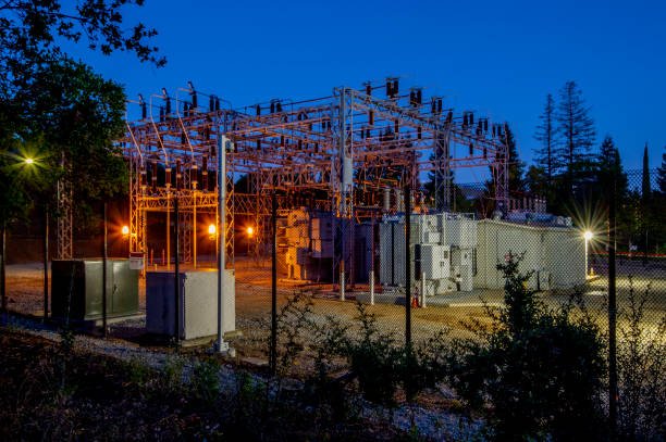
Electricity must travel through several voltage levels before it reaches an industrial facility, commercial building, or household. If voltage is not increased or reduced at the right point, transmission losses can rise, equipment can receive the wrong voltage, and the overall power system becomes inefficient or unreliable. Power transformers solve this problem by transferring electrical energy between circuits through electromagnetic induction while changing voltage and current levels. Understanding how a power transformer works across generation, transmission, and distribution is therefore essential for engineers, utilities, EPC contractors, and buyers who need to select equipment that can operate reliably at each stage of the electrical network.
A power transformer works by using alternating current in a primary winding to create changing magnetic flux in a core, which induces voltage in a secondary winding. In generation systems, transformers typically step generator voltage up for efficient transmission; in transmission substations, they change voltage between network levels; and in distribution systems, they step voltage down to levels suitable for industrial, commercial, and residential loads. The turns ratio establishes the fundamental voltage relationship, while transformer capacity, impedance, insulation, cooling, losses, and tap configuration determine practical performance.
The same electromagnetic principle operates throughout the electrical grid, but the transformer's design changes according to its position, voltage level, power capacity, load characteristics, and operating environment. Looking at the complete path from generator to end user makes it much easier to understand why different power transformers are required and what buyers should evaluate when specifying them.
[Featured Image Placeholder: A complete electrical power-system diagram showing a generator, step-up transformer, high-voltage transmission lines, transmission substation, distribution transformer, and industrial/residential loads.]
AI image prompt: [Subject] complete electrical power system from electricity generation through transmission and distribution, showing generator, step-up power transformer, high-voltage transmission lines, transmission substation transformers, distribution transformer, and end-user loads, [Style/Medium] photorealistic engineering infographic combined with precise technical illustration, [Details/Attributes] clearly differentiated voltage levels, copper windings, laminated magnetic cores, substations, overhead transmission towers, switchgear, industrial and residential loads, directional energy-flow annotations, realistic equipment proportions, [Environment/Setting] modern utility power grid extending from a generating station through substations to an industrial and residential area, [Mood/Atmosphere] professional, technically authoritative, educational, reliable, [Lighting] clean daylight with controlled industrial highlights and excellent visibility of electrical equipment.
Power transformers are used only to increase voltage for long-distance transmission.False
Transformers are used throughout the power system for both voltage step-up and step-down duties, including generation, transmission substations, distribution, and industrial applications.
How Does a Power Transformer Transfer Electrical Energy?
A power transformer does not normally transfer electricity through a direct electrical connection between its primary and secondary windings. Instead, it transfers energy magnetically through the transformer core. When alternating voltage is applied to the primary winding, an alternating current produces changing magnetic flux in the magnetic core. This changing flux links the secondary winding and induces an electromotive force in it. The voltage generated in each winding depends fundamentally on the number of turns exposed to the common magnetic flux. Therefore, the winding with more turns develops a higher voltage, while the winding with fewer turns develops a lower voltage. The turns ratio consequently determines the transformer's fundamental voltage conversion. At the same time, current changes approximately inversely with voltage for a given transferred power, so a step-up transformer generally produces higher voltage and lower current, while a step-down transformer produces lower voltage and higher current. Real transformers are not lossless. Copper losses occur in the windings, core losses occur because of hysteresis and eddy currents, and additional stray and dielectric losses can occur depending on construction and operating conditions. These losses produce heat, which must be removed by an appropriate cooling system. Transformer impedance also affects voltage regulation and short-circuit current. This is why the basic induction principle alone cannot determine whether a transformer is suitable for a particular power-system application. Engineers must consider rated voltage, rated capacity, frequency, impedance, insulation level, cooling method, tap range, connection configuration, environmental conditions, and required testing. Nevertheless, the same electromagnetic induction mechanism remains the foundation of every conventional power transformer, whether it is installed immediately after a generator, inside a high-voltage transmission substation, or near the final distribution network.
Why Is Voltage Increased for Transmission?
The principal reason for increasing voltage for transmission is to reduce current for a given amount of transmitted power. Lower current reduces resistive losses in conductors and can improve the efficiency of long-distance power transfer. For example, consider a simplified transmission scenario in which the same apparent power is transmitted at two different voltage levels. If the voltage is increased by a factor of ten, the approximate current required for the same power is reduced by a factor of ten. Because resistive conductor losses depend on current squared, the idealized loss component associated with the same conductor resistance can decrease dramatically. This simplified calculation explains the fundamental economic value of high-voltage transmission. It does not mean that higher voltage is always better without limitation. Higher system voltage requires greater insulation clearances, more sophisticated equipment, appropriate line design, stronger electrical coordination, and suitable protection systems. Transformers make these voltage changes practical because their turns ratio can increase or decrease voltage without changing the system frequency. A transmission transformer therefore acts as a critical interface between different parts of the grid. Its impedance also has a major influence on fault-current behavior. A transformer with low impedance may allow greater short-circuit current to flow, while higher impedance can limit fault current but may increase voltage drop. Engineers must balance these characteristics according to system requirements. Transformer efficiency also matters because losses accumulate over long operating periods. A transformer that operates continuously can consume substantial energy through no-load and load losses even when its losses are small relative to its total power rating. This is why utilities and industrial buyers evaluate transformer losses, efficiency, temperature rise, and lifecycle economics rather than simply comparing purchase prices.
| Power-System Stage | Typical Transformer Function | Main Electrical Objective | Important Design Considerations |
|---|---|---|---|
| Generation | Step-up | Increase voltage before transmission | Generator voltage, MVA, insulation, fault duty, cooling |
| Bulk transmission | Step-up/step-down | Connect different network voltage levels | System voltage, impedance, regulation, insulation |
| Transmission substation | Step-down | Reduce transmission voltage | Load profile, tap range, fault level, cooling |
| Distribution | Step-down | Supply utilization networks | Secondary voltage, kVA, efficiency, installation conditions |
| Industrial facility | Step-down or voltage matching | Provide equipment operating voltage | Motor loads, harmonics, impedance, protection |
| Renewable-energy plant | Step-up/step-down | Interface generation with grid | Variable generation, grid code, harmonics, insulation |
How Do Transmission Substations Use Power Transformers?
Transmission substations use power transformers to change voltage between different portions of the electrical network. A large transmission network may operate at one voltage level for bulk transfer and another lower level for regional transmission or distribution. The transformer provides the electrical interface between these systems. At a receiving substation, a step-down transformer reduces the voltage so that electricity can move into lower-voltage networks. The transformer does more than simply change voltage. Its impedance influences the network's fault-current distribution, its voltage regulation affects the voltage delivered to downstream equipment, and its tap system can help compensate for changing system conditions. Large transformers are therefore among the most strategically important pieces of substation equipment. Their failure can cause significant service disruption and replacement can require substantial time because large power transformers are heavy, highly engineered products with specialized transportation and installation requirements. For this reason, buyers often focus strongly on manufacturing quality, routine testing, type testing, traceability, transportation planning, spare parts, and after-sales technical support. The transformer's winding arrangement must also be compatible with the required phase displacement and system grounding configuration. Vector group selection can affect how transformers operate within a larger network and is particularly important when transformers are operated in parallel. Cooling is another major consideration because transformer losses increase temperature. Large oil-immersed transformers may use natural or forced circulation arrangements, while dry-type transformers rely on air-based heat transfer. The appropriate solution depends on rating, installation environment, fire requirements, maintenance philosophy, and project specifications. Thus, a transmission substation transformer should be treated as a complete engineered system rather than a simple voltage-conversion device.
How Does a Distribution Transformer Complete the Voltage Reduction?
After electricity has passed through transmission and regional networks, distribution transformers reduce voltage to levels suitable for final utilization. The distribution transformer is therefore the final major voltage-conversion stage before electricity reaches many industrial, commercial, and residential loads. Depending on the network, the transformer may supply low-voltage service directly to buildings or provide a lower distribution voltage that is subsequently used by local equipment. Distribution transformers are generally much closer to end users than large transmission transformers, so their design must account for local installation conditions and load behavior. Some operate outdoors in utility environments, while others are installed inside commercial or industrial facilities. Distribution transformer efficiency is particularly important because many units remain energized continuously, meaning that no-load losses can accumulate even when the connected load is relatively small. When selecting a distribution transformer, buyers should therefore consider both load losses and no-load losses, not just the rated kVA and nominal voltage. The transformer should also be selected according to expected load growth. A unit operating close to its maximum capacity continuously may experience excessive temperature rise, while a significantly oversized transformer can create unnecessary capital cost and may increase the impact of no-load losses. The correct balance requires an understanding of present demand, future expansion, load diversity, ambient temperature, installation altitude, harmonics, and required overload capability. For industrial sites, the load may include motors, welding equipment, variable-frequency drives, rectifiers, furnaces, and other nonlinear or rapidly changing loads. These conditions can require additional design consideration beyond the basic transformer ratio. A distribution transformer is therefore the point where broad grid engineering becomes closely connected to the actual electrical characteristics of the end user's facility.
How Do Transformers Manage Different Voltage Levels?
The power grid can be viewed as a sequence of voltage transformations rather than one continuous voltage system. Electricity may leave a generator at one voltage, be increased to a much higher transmission voltage, reduced at a transmission substation, reduced again at a distribution substation, and finally supplied to utilization equipment at a lower voltage. The transformer turns ratio establishes the fundamental relationship between these levels. However, system voltage does not remain perfectly constant because generator conditions, network loading, line impedance, and other operating factors vary. This is why many power transformers incorporate taps. By changing the effective number of active winding turns, the transformer can adjust its effective ratio within a designed range. Tap changers can therefore help maintain an appropriate downstream voltage as operating conditions change. Depending on the application, the tap system may be operated only when the transformer is de-energized or may be designed for on-load voltage regulation. Selecting the tap arrangement requires consideration of voltage variation, load characteristics, switching duty, maintenance, insulation coordination, and system-control requirements. For buyers, the important lesson is that a transformer specification should identify not only the nominal primary and secondary voltages but also the tap range and tap operating requirements when voltage regulation is important. The transformer must also have appropriate insulation levels for the highest system voltage and expected transient stresses. This becomes increasingly important as transformer voltage class increases. The complete electrical design therefore connects turns ratio, insulation, impedance, regulation, and protection. A manufacturer should be able to explain how these parameters interact rather than treating them as independent nameplate values.
How Do Transformer Losses Affect Generation, Transmission, and Distribution?
Every power transformer has losses, and these losses occur regardless of whether the transformer is operating at full load. Core losses are associated primarily with magnetization of the core and continue while the transformer is energized. Load losses are strongly associated with winding current and therefore vary with load. Additional losses can occur in structural components and other parts of the transformer because of stray magnetic fields. The practical importance of these losses depends on the transformer's operating profile. A generator transformer may operate at a relatively high load factor, making load-related losses important. A distribution transformer may remain energized around the clock while experiencing substantial periods of low load, making no-load losses particularly important. This difference illustrates why transformer efficiency must be evaluated in the context of actual operating duty rather than by looking at a single efficiency value. Thermal performance is directly connected to losses because nearly all transformer losses ultimately become heat. Excessive temperature accelerates insulation aging and can reduce service life. Cooling system selection must therefore be matched to transformer losses, ambient conditions, and required loading. Manufacturers verify losses and other electrical characteristics through appropriate factory testing. Buyers should compare guaranteed loss values and test requirements against the project specification and applicable standards. Lifecycle cost can be more meaningful than initial purchase price when a transformer operates continuously for many years. A transformer that costs slightly more but has substantially lower losses can potentially provide significant long-term energy savings. For utility-scale and industrial projects, this lifecycle perspective is particularly valuable because even a relatively small difference in transformer losses can accumulate into a significant energy cost over decades of operation.
| Parameter | Generation Transformer | Transmission Transformer | Distribution Transformer |
|---|---|---|---|
| Primary role | Generator-to-grid interface | Network voltage conversion | Final voltage reduction |
| Typical loading concern | High continuous loading | Network loading and contingencies | Load diversity and long energization time |
| Voltage ratio | Usually step-up | Step-up or step-down | Usually step-down |
| Major thermal concern | High load losses | Load and system contingency duty | Combination of no-load and load losses |
| Impedance importance | Fault and system coordination | Strong influence on network faults | Important for regulation and fault performance |
| Tap requirements | Project dependent | Often important | Application dependent |
| Cooling | Frequently advanced cooling | Often oil-immersed with engineered cooling | Liquid-immersed or dry-type depending on installation |
| Buyer focus | Reliability and generator compatibility | Grid integration and fault performance | Efficiency, cost, installation, and load profile |
How Should Buyers Evaluate How a Power Transformer Works When Selecting Transformer Equipment?

Buying a power transformer based only on voltage, kVA, or a supplier's product catalog can create expensive problems later. A transformer may have the correct nameplate voltage yet perform poorly under actual load because its impedance, voltage regulation, cooling, insulation system, losses, or winding configuration does not match the application. Buyers who understand how a power transformer works can evaluate equipment more effectively because they can connect every major specification to an actual operating function. Instead of treating the transformer as a black box, the buyer can examine how electromagnetic induction transfers energy, how the turns ratio establishes voltage conversion, how current produces winding losses, how the core carries magnetic flux, and how the cooling and insulation systems maintain reliability. This approach reduces the risk of selecting equipment that appears technically suitable on paper but cannot provide the required performance throughout its service life.
Buyers should evaluate how a power transformer works by connecting its operating principle to the required voltage ratio, rated capacity, load current, impedance, efficiency, voltage regulation, insulation, cooling, tap configuration, and testing requirements. A suitable transformer should not only produce the required nominal voltage but also maintain acceptable performance under the project's real load, temperature, fault, environmental, and operating conditions.
The most useful evaluation method is to move from the transformer's basic electromagnetic operating principle to its practical specifications. The following sections explain what buyers should look for, what each specification means, which questions to ask a manufacturer, and how to distinguish a technically complete transformer proposal from one that provides only attractive headline specifications.
[Featured Image Placeholder: An electrical engineer inspecting a large power transformer with visible windings, laminated core, bushings, cooling system, nameplate, and factory testing equipment.]
AI image prompt: [Subject] professional electrical engineer evaluating a large industrial power transformer, [Style/Medium] photorealistic engineering documentary image with precise technical visualization, [Details/Attributes] visible transformer tank, copper windings, laminated magnetic core cutaway, high-voltage bushings, cooling radiators, monitoring instruments, nameplate specifications, factory testing equipment and inspection documents, [Environment/Setting] modern power-transformer manufacturing and testing facility, [Mood/Atmosphere] professional, analytical, reliable, quality-focused, [Lighting] bright controlled industrial lighting with clear highlights and detailed component visibility.
A transformer with the correct rated primary and secondary voltage is automatically suitable for the application.False
Transformer suitability also depends on capacity, load profile, impedance, losses, regulation, insulation, cooling, taps, environmental conditions, and applicable testing requirements.
How Does a Power Transformer Actually Work?
Before evaluating transformer equipment, buyers should understand the basic mechanism. A conventional power transformer uses alternating current in a primary winding to establish changing magnetic flux in a magnetic core. This changing flux links the secondary winding and induces an electromotive force. The number of turns on each winding establishes the fundamental voltage relationship. A winding with more turns develops a higher voltage, while a winding with fewer turns develops a lower voltage. The transformer therefore changes voltage without changing the fundamental power-system frequency. For an ideal transformer, increasing voltage corresponds approximately to decreasing current for the same transferred power. Real transformers, however, are not ideal. Copper resistance causes load losses and heat, magnetic hysteresis and eddy currents produce core losses, leakage flux contributes to leakage reactance, and other stray losses can occur. These effects influence voltage regulation, temperature rise, efficiency, and short-circuit performance. This is why a buyer should not interpret transformer operation as simply “high voltage in, low voltage out.” The complete transformer is an electromagnetic, thermal, mechanical, and dielectric system. The core must carry magnetic flux without excessive saturation; the windings must carry their rated current without unacceptable temperature rise; insulation must withstand normal and transient voltage stresses; the tank and structural components must withstand mechanical forces; and the cooling system must remove generated heat. When a buyer understands these relationships, transformer specifications become easier to interpret. Rated kVA or MVA describes the power-transfer scale, while the voltage ratio describes voltage conversion. Impedance influences fault current and regulation. Loss guarantees indicate energy performance. Cooling determines how heat is removed. Insulation levels define dielectric capability. Tap arrangements allow controlled adjustment of the effective voltage ratio. Factory tests then provide evidence that the manufactured transformer actually meets the specified design. This functional approach is much more reliable than comparing transformers by catalog dimensions or purchase price alone.
How Should Buyers Evaluate the Transformer Turns Ratio?
The turns ratio should be one of the first electrical parameters buyers verify because it establishes the transformer's fundamental voltage conversion. If a transformer receives 11 kV and must deliver 400 V, the nominal primary-to-secondary voltage ratio is approximately 27.5:1. The manufacturer uses the corresponding winding relationship when designing the transformer. However, buyers should not stop at the nominal ratio. They should determine whether the transformer includes taps, where those taps are located, what range they provide, and whether they are operated on-load or off-circuit. Tap arrangements can compensate for variations in system voltage and help maintain suitable downstream voltage. The buyer should also ask how the supplier defines rated voltage in relation to the tap positions. This is particularly important when the incoming utility voltage can vary significantly or when the secondary supplies voltage-sensitive equipment. In a factory acceptance test, the winding ratio should be verified against the design information, and transformers with multiple taps should be evaluated across the relevant tap positions. Buyers should also make sure the winding connection and phase relationship are correct. For three-phase transformers, vector group and winding configuration affect how the transformer integrates with the electrical network and whether parallel operation is possible. A technically strong supplier should explain the relationship among rated voltage, turns ratio, tap range, winding connection, and vector group rather than providing these values as unrelated data points. The buyer's objective is not merely to confirm that the transformer can theoretically convert one voltage to another; it is to verify that the transformer can provide the required operating voltage across the expected system conditions. This distinction becomes increasingly important in industrial facilities, renewable-energy installations, substations, and other applications where voltage variations and changing loads are expected.
| Buyer Requirement | What to Evaluate | Why It Matters |
|---|---|---|
| Primary voltage | Rated voltage and allowable system variation | Determines primary winding and insulation requirements |
| Secondary voltage | Rated output voltage | Must match downstream equipment |
| Turns ratio | Nominal winding ratio | Establishes fundamental voltage conversion |
| Tap range | Number, location, and percentage of taps | Allows voltage adjustment |
| Tap operation | On-load or off-circuit | Determines operational flexibility |
| Phase configuration | Winding connection and vector group | Affects system integration |
| Frequency | Rated system frequency | Directly affects magnetic flux and core operation |
How Does Rated Capacity Relate to How the Transformer Works?
Rated capacity, normally expressed in kVA or MVA, indicates how much apparent power the transformer is designed to transfer under specified operating conditions. This is different from voltage ratio. Two transformers may both convert 13.8 kV to 480 V but have completely different power ratings. A smaller transformer may supply a relatively modest industrial load, while a much larger unit may serve a major facility or substation. Rated capacity determines the approximate winding current at a given voltage and therefore has a direct effect on conductor size, thermal design, terminals, bushings, cooling, and mechanical strength. Buyers should calculate the present connected load and then consider demand factor, diversity, motor starting, future expansion, and possible overload requirements. Simply adding the nameplate ratings of every connected machine can result in an unnecessarily large transformer because many loads do not operate simultaneously. Conversely, choosing a transformer too close to its continuous expected load can leave insufficient margin for growth, ambient-temperature effects, or unusual operating conditions. The load profile is therefore as important as the peak load. Motors, welding systems, furnaces, rectifiers, variable-frequency drives, data-center equipment, and renewable-energy converters can impose different electrical stresses on the transformer. A professional supplier should review the load characteristics before finalizing the design. Buyers should also understand that transformer capacity interacts with cooling. A transformer may be capable of transferring a specified rating under a particular cooling condition, but allowable loading can change if cooling conditions deteriorate. Ambient temperature and installation altitude can also influence thermal performance. For large transformers, emergency loading may be possible under controlled conditions, but buyers should distinguish between continuous rated capacity and temporary overload capability. The safest specification therefore states the required rated capacity, expected loading profile, ambient conditions, cooling arrangement, and overload requirements. This allows the manufacturer to design the windings, core, insulation, and cooling system as one coordinated system.
Why Should Buyers Evaluate Transformer Impedance?
Transformer impedance is important because it affects both voltage regulation and short-circuit current. When a transformer supplies a load, current flows through winding resistance and leakage reactance. These internal impedances produce voltage drops between the transformer's internal induced voltage and its external terminal voltage. As load current increases, the effect becomes more significant. Impedance also influences the magnitude of fault current that can pass through the transformer. A transformer with lower impedance can permit greater fault current, while higher impedance can provide stronger current limitation but may produce greater voltage drop under load. Therefore, impedance is not simply a number for comparing products; it is a critical system-integration parameter. Buyers should specify the required impedance according to the network study and protection design rather than accepting an arbitrary supplier value. This is especially important when transformers are connected in parallel. Transformers intended for parallel operation generally need compatible voltage ratios, phase relationships, impedance characteristics, and other relevant parameters. Significant mismatch can cause circulating currents and uneven load sharing. During procurement, buyers should ask the manufacturer for the guaranteed impedance value and its tolerance, the test method, and the relationship between impedance and short-circuit performance. For large power transformers, the buyer should also consider whether the transformer has been mechanically designed to withstand the electromagnetic forces associated with prospective fault currents. A supplier that provides only nominal voltage and kVA without discussing impedance is not giving the buyer enough information for a complete system assessment. The transformer must work as part of the electrical network, not independently from it.
How Should Buyers Evaluate the Transformer Insulation System?
The insulation system separates energized conductors from the core, tank, other windings, and ground. It must withstand normal operating voltage as well as temporary and transient stresses. In higher-voltage power transformers, insulation coordination becomes particularly important because lightning impulses, switching events, system faults, and other disturbances can produce voltages substantially different from normal operating voltage. Buyers should therefore evaluate insulation levels, winding-to-ground clearances, winding-to-winding insulation, bushings, dielectric materials, and applicable dielectric tests. For oil-immersed transformers, the insulating liquid performs both electrical-insulation and heat-transfer functions, so liquid quality and processing are important. For dry-type transformers, the solid insulation system and air clearances are central to dielectric and thermal performance. Environmental conditions also matter. High humidity, pollution, altitude, dust, salt, and chemical exposure can affect external insulation and cooling. The transformer enclosure and accessories must therefore be appropriate for the actual installation environment. Buyers should ask the manufacturer to explain the insulation system and provide relevant design and test information. Factory testing can include applied-voltage and induced-voltage tests and, depending on transformer type and specification, additional impulse or other dielectric tests. The exact test program should follow the applicable project and standard requirements. Buyers should not assume that every transformer requires the same test package. Instead, they should identify the transformer's voltage class and application and then establish an appropriate acceptance program. A technically capable manufacturer should be able to demonstrate how insulation design, clearances, bushings, grounding, and dielectric testing work together to protect the transformer throughout its service life.
How Does the Cooling System Support Transformer Operation?
Cooling is essential because transformer losses generate heat. If heat is not removed effectively, winding and insulation temperatures can rise beyond acceptable limits. The cooling method therefore forms an important part of how the transformer works in real operating conditions. Small and medium transformers may use relatively simple natural cooling arrangements, while larger units can use radiators, fans, pumps, or combinations of natural and forced circulation. Dry-type transformers rely on air movement and must be installed where sufficient ventilation is available. Buyers should evaluate the cooling designation, rated temperature rise, ambient-temperature assumptions, altitude, ventilation, fan or pump redundancy where applicable, monitoring, and alarm functions. The buyer should also ask what happens if a cooling component fails. For critical installations, redundancy can be valuable because a single failed fan or pump should not necessarily cause an immediate forced shutdown. Temperature monitoring can provide early warning of abnormal operating conditions. For oil-immersed transformers, oil temperature and winding-temperature monitoring can provide important information about thermal conditions. Cooling equipment should also be included in the maintenance plan. Fans, pumps, radiators, control circuits, and temperature sensors can all affect transformer availability. A transformer that has excellent electrical performance but inadequate cooling for its installation environment may not achieve its expected service life. This is why buyers should provide the manufacturer with realistic ambient temperature, altitude, enclosure, ventilation, indoor/outdoor, and loading information. The supplier can then select a suitable cooling configuration and calculate the expected temperature rise. The buyer should verify that the guaranteed thermal performance corresponds to the intended operating conditions rather than assuming that the published rated capacity applies identically in every environment.
Why Are Factory Tests Important When Evaluating How a Transformer Works?
Factory testing provides objective evidence that the manufactured transformer conforms to its design and specified requirements. Buyers should not regard testing as an administrative step that occurs after the important engineering decisions have already been made. Testing is part of the technical evaluation because it verifies characteristics directly related to transformer operation. Ratio testing checks the winding relationship and helps identify connection or winding problems. Winding-resistance measurements provide information about winding continuity and resistance characteristics. Loss and impedance measurements help verify the transformer's electrical performance. Insulation-related tests evaluate dielectric capability. Additional type or special tests may be required depending on transformer design, voltage level, purchaser requirements, and applicable standards. Buyers should therefore establish the factory acceptance test program before placing the order rather than negotiating it after manufacturing is complete. The test report should identify the transformer, winding configuration, test conditions, measured values, and acceptance criteria clearly enough for independent review. For transformers with tap changers, relevant tap positions should be addressed. For three-phase units, phase relationships and winding connections should be consistent with the approved drawings. A strong manufacturer's testing process should also provide traceability from materials and winding production through assembly and final inspection. This is particularly valuable for large power transformers because correcting a manufacturing problem after transportation and installation can be costly. Buyers should also distinguish between routine tests, type tests, and special tests. Not every test is performed on every transformer, and a proper test program should be based on the specific equipment and project requirements. The most useful supplier is one that can explain what each test proves about the transformer's operation and why the test is relevant to the intended application.
How Can Buyers Compare Transformer Suppliers More Effectively?
The supplier should be evaluated not only by the transformer specification but also by its ability to demonstrate how that specification is achieved. Buyers should examine manufacturing equipment, winding technology, core-processing capability, drying and insulation processes, assembly facilities, testing equipment, quality systems, engineering resources, and production traceability. A supplier that claims a high production capacity should be able to demonstrate that capacity through actual equipment, workforce, production records, testing resources, and delivery history. Quality certification is useful, but buyers should also examine how quality control is implemented on the factory floor. Incoming material inspection, winding-process control, core assembly, drying, final assembly, electrical testing, documentation, and nonconformance management should form a traceable process. Buyers should also request references for comparable transformers, particularly when the project involves high voltage, high capacity, special cooling, unusual loads, or challenging environmental conditions. Delivery performance is another useful indicator. A manufacturer may have excellent technical documentation but limited ability to deliver large quantities within the required schedule. Buyers should evaluate current production commitments, historical lead times, testing capacity, and logistics planning. After-sales support should also be considered. Spare parts, troubleshooting, commissioning assistance, maintenance documentation, warranty support, and technical communication can have substantial value during the transformer's operating life. The strongest procurement process therefore evaluates the supplier as an engineering and manufacturing partner rather than simply as a source of equipment. When suppliers are compared using the same technical questionnaire and acceptance criteria, buyers can identify differences that are hidden by catalog prices.
| Supplier Evaluation Area | Questions Buyers Should Ask | Evidence to Request |
|---|---|---|
| Engineering | Can the supplier perform application-specific transformer design? | Design calculations, drawings, technical proposals |
| Manufacturing | Does factory equipment match the proposed capacity? | Factory inspection, equipment list, production records |
| Winding | How are conductor arrangement and insulation controlled? | Process documentation, inspection records |
| Core | How is magnetic-core quality controlled? | Material certificates, process records |
| Drying | How is moisture controlled before assembly? | Drying-process records |
| Testing | Can the factory perform required acceptance tests? | Test-equipment list and sample reports |
| Quality | How are nonconformities controlled? | QMS procedures and records |
| Delivery | Can production meet the project schedule? | Historical delivery data and production plan |
| Service | What support is available after delivery? | Warranty and service procedures |
What Is a Practical Buyer Checklist for Power Transformer Selection?
A practical evaluation should begin with the electrical system and then move toward equipment construction. First, define the transformer's application: generator step-up, transmission, substation, distribution, industrial, renewable-energy, or another duty. Second, define primary and secondary rated voltage, frequency, phase number, connection configuration, vector group, rated capacity, and expected load profile. Third, establish impedance, regulation, tap range, insulation levels, cooling method, temperature-rise requirements, and environmental conditions. Fourth, define guaranteed losses and the required lifecycle performance. Fifth, establish the applicable standards and factory acceptance tests. Sixth, evaluate the supplier's manufacturing and testing capability. Seventh, verify that the final technical documents, nameplate information, drawings, and test reports are mutually consistent. This sequence helps prevent a common procurement error: starting with a supplier's available model and attempting to make the project requirements fit the product. The correct approach is the opposite. The buyer defines the operating duty first, and the manufacturer demonstrates how the transformer design satisfies it. For large or technically demanding transformers, a pre-award technical meeting can be valuable. Engineers can review the load study, system voltage, fault level, tap requirements, cooling, insulation, accessories, testing, transportation, and commissioning requirements together. Any deviations from the specification should be documented rather than accepted informally. Buyers should also distinguish mandatory requirements from preferred features so that supplier quotations can be compared consistently. Finally, the buyer should consider total ownership cost rather than purchase price alone. A transformer with lower losses, appropriate thermal margin, reliable accessories, strong testing documentation, and good service support may provide better value over its operating life than a cheaper transformer with uncertain performance.
Conclusion
A power transformer works by using electromagnetic induction and the turns ratio between its windings to transfer AC electrical energy from one circuit to another at a different voltage level. Its core, windings, insulation, cooling system, and protection components work together to provide safe, efficient, and reliable operation. For buyers, understanding this operating principle makes it easier to interpret transformer ratings, compare designs, assess efficiency, and select equipment that matches the actual requirements of the electrical system.
FAQ
Q1: What is a power transformer and what does it do?
A1: A power transformer is an electrical device designed to transfer electrical energy between circuits while increasing or decreasing voltage. It does this without changing the frequency of the electrical supply. Power transformers are mainly used in electricity generation, transmission, substations, and large industrial power systems.
The main purpose of a power transformer is to make electricity suitable for different stages of the power network. Electricity generated at a power station may need to be raised to a much higher voltage before it travels over long distances. At substations, transformers can then reduce the voltage for subsequent transmission or distribution stages.
A power transformer does not generate electricity. Instead, it transfers existing electrical energy from one circuit to another through magnetic coupling. Its operation depends on the relationship between electrical current and a changing magnetic field.
A typical transformer contains two or more windings positioned around a magnetic core. The winding connected to the incoming electrical supply is generally called the primary winding, while the winding connected to the outgoing circuit is the secondary winding. The number of turns in each winding determines how the voltage is transformed.
When the secondary winding has more turns than the primary winding, the transformer can increase voltage. When it has fewer turns, the transformer can reduce voltage. This makes transformers extremely useful for managing different voltage levels throughout an electrical network.
Power transformers can also differ significantly in construction. Some use insulating liquid for electrical insulation and heat removal, while others use air and solid insulation. The appropriate design depends on voltage, capacity, installation environment, safety requirements, maintenance strategy, and application.
Large power transformers are particularly important because they can handle substantial electrical loads. They are commonly found in generating plants and high-voltage substations, where reliable voltage conversion is essential for maintaining the flow of electricity.
For buyers, understanding the basic purpose of a power transformer is the first step toward evaluating specifications. Voltage ratio, rated capacity, frequency, insulation, cooling method, efficiency, impedance, and installation conditions all need to match the intended electrical system.
Q2: How does a power transformer work?
A2: A power transformer works through electromagnetic induction. When alternating current passes through the primary winding, it creates a continuously changing magnetic field in the transformer's core. This changing magnetic field then produces voltage in another winding.
The process starts with the AC supply entering the primary winding. Because AC continuously changes direction, the magnetic field surrounding the winding also changes. The magnetic core concentrates and guides this magnetic flux so that it links effectively with the secondary winding.
The changing magnetic flux produces an induced voltage in the secondary winding. The magnitude of this voltage depends largely on the relationship between the number of turns in the primary and secondary windings.
For example, if the secondary winding contains substantially more turns than the primary winding, the output voltage will be higher than the input voltage. This is known as step-up operation. If the secondary contains fewer turns, the output voltage becomes lower, creating step-down operation.
The transformer therefore provides voltage conversion without requiring a mechanical system. Energy is transferred magnetically between the windings.
Although the basic operating principle is straightforward, practical power transformers involve many engineering considerations. Electrical resistance in the windings produces heat, while the magnetic core experiences energy losses during operation. Leakage magnetic flux and other physical effects can also influence transformer performance.
To manage these effects, power transformers use carefully selected magnetic materials, conductor arrangements, insulation systems, cooling structures, and mechanical supports. Larger units may include radiators, fans, pumps, monitoring equipment, tap-changing mechanisms, and protective devices.
The operating frequency is also important. Transformer dimensions, magnetic flux, core design, and winding characteristics are all related to the frequency of the electrical system. A transformer designed for one operating condition should not automatically be assumed suitable for another.
In practical applications, transformer performance is therefore the result of several systems working together. Electromagnetic induction provides the fundamental operating principle, while the core, windings, insulation, cooling, and protection systems allow the transformer to operate reliably under its specified conditions.
Q3: What are the main components of a power transformer?
A3: The main components of a power transformer include the magnetic core, windings, insulation system, tank or enclosure, cooling equipment, bushings, and control or protection accessories. Each component contributes to electrical performance, thermal management, or mechanical reliability.
Magnetic core: The core provides a low-reluctance path for magnetic flux. Its construction affects energy losses, efficiency, noise, and overall transformer performance.
Windings: The windings carry electrical current and establish the voltage relationship between the input and output sides. Their design must withstand normal operating conditions as well as electrical and mechanical stresses caused by faults or sudden changes in load.
Insulation system: Insulation prevents unwanted electrical contact between windings, the core, and grounded structures. Depending on the transformer design, insulation can involve solid materials, insulating liquid, air, or combinations of these.
Tank or enclosure: Liquid-immersed transformers generally use a tank to contain the active part and insulating liquid. The enclosure also protects internal components from external environmental conditions.
Cooling system: Transformer operation produces heat. Cooling equipment transfers this heat away from the active components. Depending on the design, cooling may use natural circulation, forced air, fans, pumps, radiators, or other methods.
Bushings: Bushings provide insulated pathways for electrical connections to pass from the internal transformer windings to external conductors.
Tap changer: Some transformers include tap-changing equipment to adjust the voltage ratio within a specified range. This can help maintain an appropriate system voltage as operating conditions change.
Monitoring and protection equipment: Larger transformers may use temperature indicators, oil-level devices, pressure-related protection, gas monitoring, winding-temperature systems, and other equipment to identify abnormal operating conditions.
These components must be designed as an integrated system. Increasing the transformer's capacity, for example, may require changes to the windings, cooling system, insulation, tank dimensions, bushings, and supporting equipment.
For buyers, reviewing individual components can reveal important differences between seemingly similar transformer offers. A complete technical evaluation should therefore consider the transformer's entire design rather than focusing only on its rated voltage and capacity.
Q4: Why are power transformers important for electricity transmission?
A4: Power transformers are essential to electricity transmission because they allow electrical systems to operate at different voltage levels. This makes it possible to move large amounts of electricity over long distances while managing transmission losses and equipment requirements.
Electricity generated at a power plant is often increased to a higher voltage before entering a transmission network. For a given amount of transferred power, higher voltage generally means lower current. Lower current can reduce resistive losses in transmission conductors.
When electricity reaches a substation closer to its destination, transformers can reduce the voltage to another suitable level. Additional transformers may perform further voltage reduction before electricity reaches distribution networks and individual loads.
This creates a chain of voltage transformations throughout the power system. Without transformers, generation, transmission, distribution, and consumption would be much more difficult to integrate efficiently.
Power transformers also allow electrical equipment designed for different voltage levels to operate as part of the same overall network. Generators, transmission lines, substations, industrial facilities, renewable-energy installations, and distribution systems can therefore be connected through appropriately designed transformer equipment.
Reliability is another major reason transformers are important. A large transformer can represent a critical connection within a substation. If it fails, the resulting interruption may affect a significant portion of the electrical network.
Transformer selection therefore involves more than choosing a voltage ratio. Engineers and buyers need to consider capacity, impedance, insulation level, cooling, short-circuit withstand capability, environmental conditions, protection requirements, and expected loading.
The transformer must also remain within its thermal and electrical limits during normal operation and foreseeable abnormal conditions.
In short, transformers provide the voltage flexibility that allows modern power systems to move electricity from generation facilities to end users. Their ability to increase and decrease voltage makes large-scale electricity transmission and distribution practical.
Q5: What is the difference between a power transformer and a distribution transformer?
A5: Power transformers and distribution transformers both transfer electrical energy between circuits and change voltage, but they are generally used at different stages of an electrical network and are designed around different operating requirements.
Power transformers are typically associated with generating stations and major substations. They are designed to transfer large amounts of electrical power between high-voltage or medium-to-high-voltage system levels. Their design often emphasizes high efficiency at substantial loads, strong insulation, mechanical durability, and reliable operation under demanding system conditions.
Distribution transformers are generally located closer to electricity users. Their role is to reduce distribution voltage to levels appropriate for local commercial, residential, or smaller industrial loads.
The two categories can differ in capacity, voltage range, physical size, cooling arrangement, installation method, and operating profile. However, there is no single universal boundary that separates them in every application. Industry terminology can vary depending on standards, utilities, manufacturers, and project requirements.
Loading behavior is an important distinction. A large power transformer may operate at relatively high loading for significant periods, while a distribution transformer may spend substantial time at lower loads. Consequently, the importance of different types of losses can vary between applications.
Installation conditions can also influence design. Distribution transformers may be installed in compact substations, outdoor locations, commercial buildings, or other locations where space and safety considerations are important. Large power transformers generally require substantial infrastructure for transportation, installation, cooling, maintenance, and protection.
When choosing between transformer categories, buyers should therefore focus on the actual electrical application rather than relying solely on terminology. Important factors include rated power, primary and secondary voltage, frequency, load profile, insulation requirements, cooling method, impedance, environmental conditions, efficiency targets, and applicable technical standards.
Understanding these differences helps buyers select a transformer that is appropriately sized and designed for its intended position in the electrical system.
References
Power Transformers — IEEE Technology Navigator
https://technav.ieee.org/topic/power-transformers/
IEEE C57.12.00-2021 — General Requirements for Liquid-Immersed Transformers
https://standards.ieee.org/ieee/C57.12.00/6962/
IEEE C57.12.01-2020 — General Requirements for Dry-Type Transformers
https://standards.ieee.org/ieee/C57.12.01/6775/
IEEE C57.12.80-2024 — Terminology for Power and Distribution Transformers
https://standards.ieee.org/ieee/C57.12.80/7006/
IEEE C57.12.52-2024 — Sealed Dry-Type Distribution and Power Transformers
https://standards.ieee.org/ieee/C57.12.52/10829/
IEEE C57.12.91-2026 — Standard Test Code for Dry-Type Distribution and Power Transformers
https://standards.ieee.org/ieee/C57.12.91/10863/
IEEE C57.116-2022 — Transformers Directly Connected to Generators
https://standards.ieee.org/ieee/C57.116/
IEEE Transformers, Regulators and Reactors — C57 Standards Family
https://technav.ieee.org/topic/transformers-regulators-and-reactors-c57/
IEC 60076-1 — Power Transformers, Part 1: General
https://webstore.iec.ch/en/publication/588
U.S. Department of Energy — Large Power Transformer Resilience Report
https://www.energy.gov/sites/default/files/2024-10/EXEC-2022-001242%20-%20Large%20Power%20Transformer%20Resilience%20Report%20signed%20by%20Secretary%20Granholm%20on%207-10-24.pdf