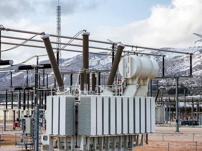
Three-phase power systems are widely used for electricity generation, transmission, distribution, and industrial power supply, but selecting the wrong transformer configuration can create problems with voltage balance, efficiency, capacity utilization, and system compatibility. Buyers may also confuse three-phase transformers with three separate single-phase units, overlooking important differences in construction, footprint, losses, maintenance, and installation. Understanding what a three-phase power transformer is and how it operates provides a practical foundation for specifying the right equipment.
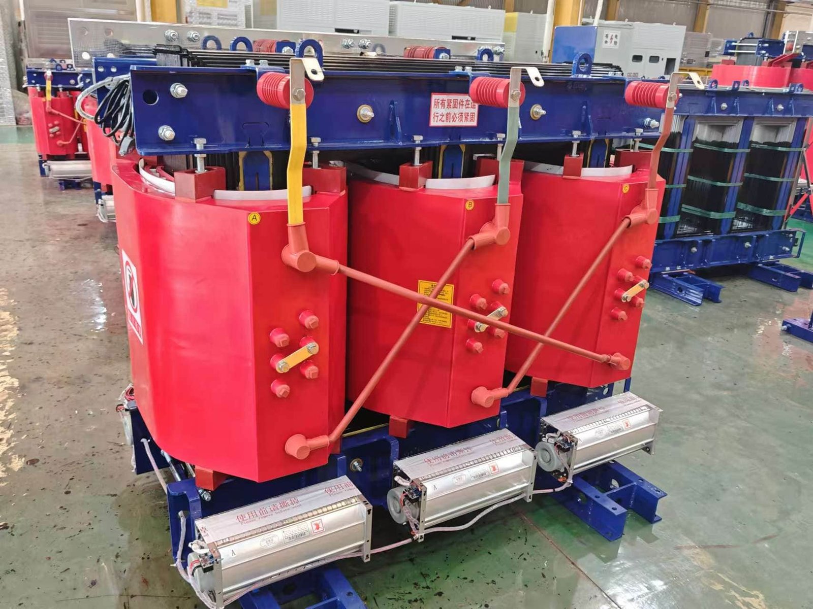
A three-phase power transformer is a transformer designed to transfer electrical energy between three-phase circuits while changing voltage levels through electromagnetic induction. It normally uses three interconnected primary and secondary winding phases and a common magnetic core assembly, with winding connections such as delta or wye selected according to system requirements. Three-phase power transformers provide efficient voltage transformation for utility grids, industrial facilities, substations, renewable-energy systems, and other applications requiring three-phase power.
A three-phase transformer is more than simply a larger version of a single-phase transformer. Its winding arrangement, phase relationships, vector group, impedance, cooling system, and connection configuration all influence how it integrates into an electrical network. The following outline explains its working principle, construction, applications, and the key factors buyers should consider during selection.
What Is a Three-Phase Power Transformer and How Does a Three-Phase Power Transformer Work?
Three-phase electricity is widely used in power generation, transmission, industrial plants, and large commercial buildings. Without a suitable transformer, the voltage supplied by the grid may not match the voltage required by motors, distribution systems, or industrial equipment. Choosing the wrong transformer can lead to excessive losses, voltage problems, overheating, and unnecessary operating costs. Understanding the basic construction and working principle of a three-phase power transformer makes it much easier to select the right equipment.
A three-phase power transformer transfers electrical energy between three-phase circuits through electromagnetic induction. It normally uses three magnetic core limbs and three sets of primary and secondary windings. The primary windings receive three-phase AC power, create changing magnetic flux in the core, and induce corresponding voltages in the secondary windings. The turns ratio determines the voltage change, while the core, windings, insulation, and cooling system determine overall performance.
For buyers, the important point is that a three-phase transformer is not simply three independent transformers placed together. Its three magnetic circuits and electrical connections must work as one coordinated system. The following sections explain the principle in simple terms.
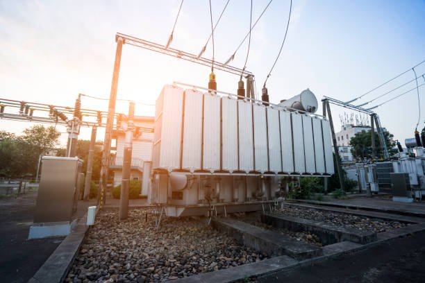
A three-phase power transformer transfers electrical energy directly through the magnetic core from the primary winding to the secondary winding.False
The magnetic core provides a path for changing magnetic flux. Electrical energy is transferred between primary and secondary circuits through electromagnetic induction, not by electrical current flowing through the core.
What Are the Main Parts of a Three-Phase Power Transformer?
A typical three-phase power transformer contains three main magnetic core limbs and corresponding primary and secondary windings. Depending on the application, it may also include transformer oil, a tank, radiators, bushings, tap equipment, protection devices, and monitoring accessories.
The magnetic core is usually made from laminated electrical steel. The laminations reduce eddy-current losses and provide an efficient path for magnetic flux.
The windings are made from insulated conductors, commonly copper or aluminum. The high-voltage and low-voltage windings are arranged and insulated according to the required voltage, current, impedance, and mechanical strength.
A simplified structure is:
       Three-Phase Transformer

       Phase A   Phase B   Phase C
          │         │         │
       Primary   Primary   Primary
       Winding   Winding   Winding
          │         │         │
       ┌──┴─────────┴─────────┴──┐
       │     Magnetic Core        │
       │   │       │       │      │
       │   │       │       │      │
       └──┬─────────┬─────────┬──┘
          │         │         │
       Secondary Secondary Secondary
       Winding   Winding   Winding
          │         │         │
       Phase A   Phase B   Phase C
The exact structure varies according to transformer capacity, voltage level, cooling method, and installation requirements, but the basic principle remains the same.
How Does a Three-Phase Power Transformer Work?
The working process begins when a three-phase AC supply is connected to the primary windings. The three phase voltages are separated by 120 electrical degrees. These voltages create changing currents and magnetic fluxes in the transformer core.
The core guides the magnetic flux through the three limbs. Because the flux is continuously changing, it links with the secondary windings and induces voltage in them.
When a load is connected to the secondary side, current flows to the load. The primary side then draws additional current from the source to provide the required power.
In simple form:
Three-Phase AC
      ↓
Primary Windings
      ↓
Changing Magnetic Flux
      ↓
Magnetic Core
      ↓
Secondary Windings
      ↓
Three-Phase Output
      ↓
Electrical Load
This process is based on electromagnetic induction. There is no direct electrical connection between the primary and secondary windings in a conventional isolation transformer.
How Does the Turns Ratio Change Voltage?
The number of turns on the primary and secondary windings determines the basic voltage transformation.
\frac{V_1}{V_2}\approx\frac{N_1}{N_2}
If the primary winding has more turns than the secondary winding, the transformer reduces voltage and acts as a step-down transformer. If the secondary has more turns, it increases voltage and acts as a step-up transformer.
For example, a transformer designed to change 33 kV to 11 kV has a nominal voltage ratio of approximately 3:1. The current relationship changes in the opposite direction, allowing the transformer to transfer approximately the same apparent power, minus losses.
| Transformer Function | Primary | Secondary |
|---|---|---|
| Step-down | Higher voltage | Lower voltage |
| Step-up | Lower voltage | Higher voltage |
| Current relationship | Lower current for higher voltage | Higher current for lower voltage |
| Main control | Primary turns | Secondary turns |
Actual terminal voltage can differ from the ideal ratio because of winding resistance, leakage reactance, transformer impedance, and voltage regulation.
Why Is the Magnetic Core Important?
The magnetic core provides the path for alternating magnetic flux. A good core design helps reduce magnetizing current and energy losses.
Three-phase transformer cores are normally laminated to reduce eddy currents. Core material and flux density must also be carefully selected. If the transformer operates with excessive flux density, the core may approach saturation. This can increase magnetizing current, noise, vibration, and heating.
Core construction therefore affects both efficiency and reliability.
For buyers, useful core-related information includes:
- Core material
- Lamination thickness
- Design flux density
- Core loss
- Joint construction
- Core clamping method
- Manufacturing accuracy
These details can be more meaningful than simply asking whether the transformer uses a “high-quality core.”
How Do Windings Affect Transformer Performance?
The windings determine how electrical current enters and leaves the transformer. Their design must consider voltage, current, insulation, heat, impedance, and mechanical forces.
For example, the low-voltage winding of a large step-down transformer may carry very high current. Its conductors therefore need sufficient cross-sectional area to control temperature rise and winding losses.
The winding arrangement also affects leakage flux and transformer impedance. Appropriate impedance is important because it helps limit fault current, but excessive impedance can cause greater voltage drop.
During a short circuit, very high current can create strong electromagnetic forces on the windings. Good mechanical support is therefore essential.
This is why professional transformer manufacturing involves much more than simply producing the correct number of turns. Winding tension, conductor dimensions, insulation, spacers, pressing structures, and lead connections all need controlled production.
How Does Three-Phase Connection Affect Transformer Operation?
Three-phase transformers can use different winding connections, including star (Y) and delta (Δ) arrangements. The connection affects phase relationships, available neutral points, grounding, and system compatibility.
Common combinations include:
| Primary Connection | Secondary Connection | Typical Consideration |
|---|---|---|
| Y | Y | Suitable for certain distribution and transmission applications |
| Δ | Y | Common where a neutral is required on the secondary |
| Y | Δ | Used in various industrial and system applications |
| Δ | Δ | Useful where a delta system is required |
The correct connection depends on the electrical system rather than being a universal “best” choice. Buyers should confirm the required vector group, grounding arrangement, phase sequence, and system voltage before ordering.
How Does a Three-Phase Transformer Handle Heat?
Transformer losses become heat. The main sources are core loss and winding load loss.
Oil-immersed three-phase power transformers use insulating oil to provide both dielectric insulation and heat transfer. Hot oil moves away from the active part and transfers heat to the tank and radiators.
        Active Part
       ┌───────────┐
       │ Core +    │
       │ Windings  │
       └───────────┘
             ↑
          Hot Oil
             │
        ┌────┴────┐
        │Radiators│
        └────┬────┘
             ↓
        Heat to Air
Dry-type three-phase transformers use air or another cooling arrangement instead of insulating oil.
The cooling method must match the transformer losses and expected load. Poor thermal design can increase insulation aging and reduce service life.
What Should Buyers Check When Selecting a Three-Phase Power Transformer?
A buyer should provide complete system information instead of only requesting a specific kVA or MVA rating.
Important parameters include:
| Specification | Why It Matters |
|---|---|
| Primary voltage | Determines input voltage |
| Secondary voltage | Must match the receiving system |
| Rated kVA/MVA | Determines power capacity |
| Frequency | Affects magnetic flux |
| Phase | Confirms three-phase operation |
| Vector group | Defines phase relationship |
| Impedance | Affects fault current and voltage regulation |
| Tap range | Allows voltage adjustment |
| Cooling method | Controls temperature |
| Insulation level | Determines dielectric capability |
| Core loss | Affects no-load energy consumption |
| Load loss | Affects efficiency under load |
| Installation environment | Influences thermal and insulation design |
Buyers should also check factory testing, quality control, production capability, drawings, guaranteed losses, accessories, and technical documentation.
Why Are Three-Phase Power Transformers Widely Used?
Three-phase power transformers are particularly important because modern electrical grids and industrial systems commonly use three-phase power. A single three-phase transformer can transfer substantial power while maintaining a compact and coordinated design.
They are used in:
- Power generation plants
- Transmission substations
- Distribution networks
- Industrial facilities
- Large commercial buildings
- Renewable-energy systems
- Mining and infrastructure projects
- Motor and process-power systems
Their ability to efficiently change voltage makes it possible to transmit electricity at high voltage and then reduce it to levels suitable for industrial, commercial, and distribution loads.
The basic principle is straightforward: the primary windings create changing magnetic flux, the core guides that flux, and the secondary windings receive the changing flux and develop the output voltage. The three phases operate together with a 120-degree phase relationship.
In conclusion, a three-phase power transformer is an electrical device that transfers three-phase AC energy through electromagnetic induction. Its magnetic core provides the flux path, its windings determine voltage and current transformation, and its insulation and cooling systems support safe long-term operation. For buyers, selecting the correct voltage ratio, capacity, connection, impedance, cooling method, insulation level, and loss performance is essential for reliable transformer service.
What Are the Main Components of a Three-Phase Power Transformer?
Choosing a three-phase power transformer only by voltage and capacity can create expensive problems later. A transformer is a complete system made up of magnetic, electrical, insulation, cooling, and protection components. If the core, windings, insulation, oil system, or accessories are poorly matched, the transformer may experience excessive losses, overheating, voltage instability, or reduced service life. Knowing the main components of a three-phase power transformer helps buyers understand what they are actually purchasing and what should be checked before production.
The main components of a three-phase power transformer include the laminated magnetic core, high-voltage and low-voltage windings, insulation system, transformer tank, insulating oil, cooling equipment, bushings, tap changer, protection devices, and monitoring accessories. The magnetic core and windings perform the main electromagnetic energy-transfer function, while the other components provide insulation, cooling, mechanical support, protection, and safe operation.
Each component has a specific job, but none works completely independently. The following guide explains the most important parts from a practical transformer manufacturing and purchasing perspective.
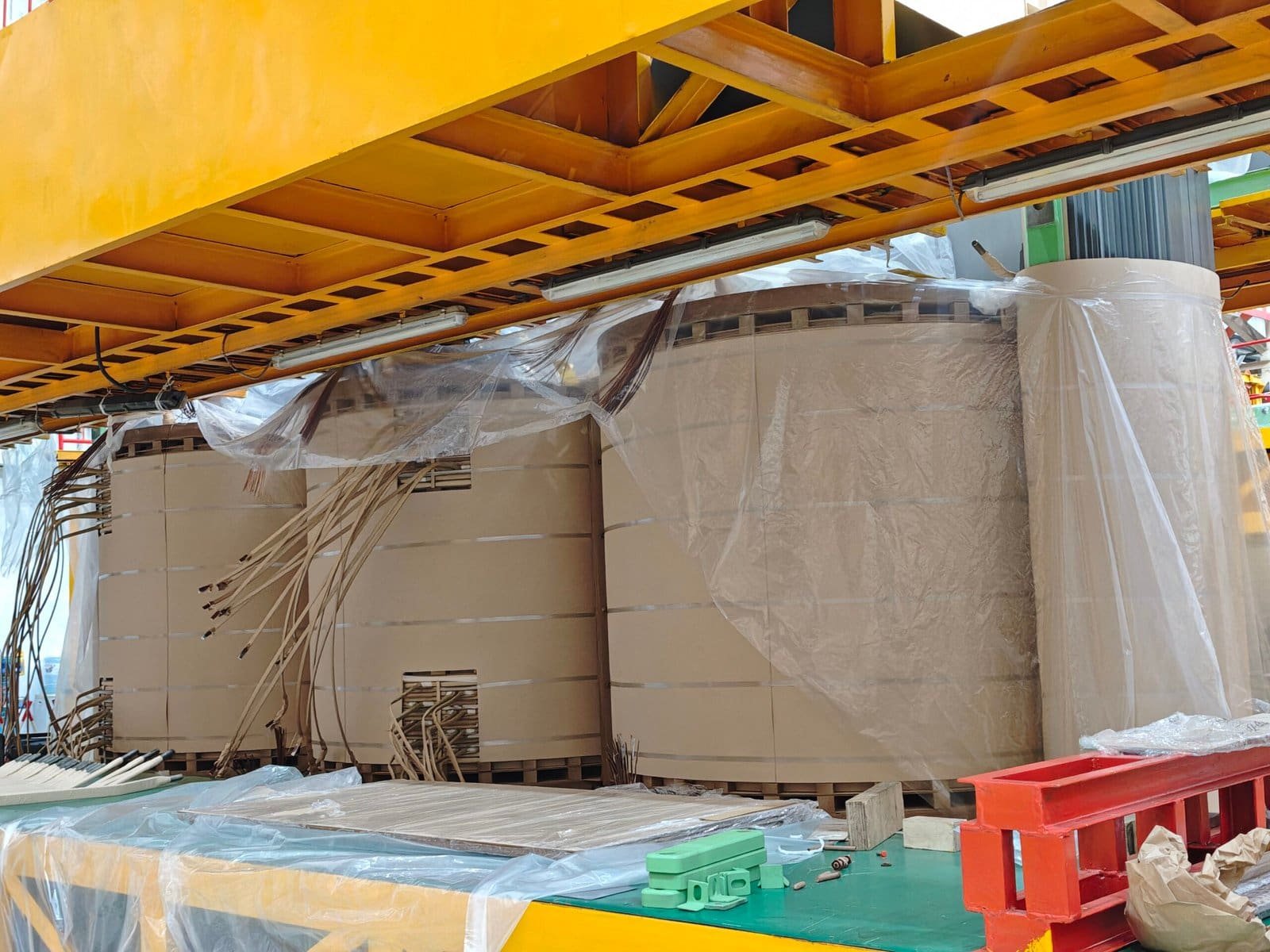
The magnetic core is the only important component of a three-phase power transformer.False
The core is essential for magnetic coupling, but windings, insulation, tank, oil, cooling, bushings, tap equipment, and protection systems are also necessary for reliable transformer operation.
What Are the Main Components of a Three-Phase Power Transformer?
A typical oil-immersed three-phase power transformer can be divided into several functional groups:
| Component | Main Function |
|---|---|
| Magnetic core | Provides a path for alternating magnetic flux |
| HV windings | Receive or deliver high-voltage electrical energy |
| LV windings | Receive or deliver lower-voltage electrical energy |
| Insulation system | Separates electrically active parts |
| Transformer oil | Provides insulation and transfers heat |
| Tank | Protects and contains the active part and oil |
| Radiators/coolers | Remove heat from the transformer |
| Bushings | Provide insulated electrical connections through the tank |
| Tap changer | Adjusts the effective turns ratio |
| Protection devices | Detect or respond to abnormal conditions |
| Monitoring devices | Measure temperature, oil level, pressure, and other conditions |
How Does the Magnetic Core Work?
The magnetic core is one of the most important components of a three-phase power transformer. It provides a low-reluctance path for the changing magnetic flux produced by the windings.
A common three-phase transformer uses three main core limbs connected by upper and lower yokes:
        Upper Yoke
   ┌──────┬──────┬──────┐
   │      │      │      │
   │ Core │ Core │ Core │
   │Limb A│Limb B│Limb C│
   │      │      │      │
   └──────┴──────┴──────┘
        Lower Yoke
The core is normally made from thin laminated electrical steel. Laminations reduce eddy-current losses and help improve efficiency.
Core design must also control magnetic flux density. Excessive flux density can push the core toward saturation, increasing magnetizing current, noise, vibration, and heating.
For buyers, important core information includes core material, lamination thickness, core loss, flux density, joint design, and clamping structure.
What Do the High-Voltage and Low-Voltage Windings Do?
The windings are the electrical components that allow the transformer to receive and deliver power.
The primary winding is connected to the input system, while the secondary winding is connected to the output system. Depending on the application, either side can be considered the input or output.
The changing current in one winding produces changing magnetic flux in the core. This changing flux links the other winding and induces a voltage.
The basic relationship is:
\frac{V_1}{V_2}\approx\frac{N_1}{N_2}
where (N) represents the number of turns.
The HV and LV windings must also be designed for different current levels. In a step-down transformer, the LV winding carries higher current, so its conductor generally needs a larger effective cross-sectional area.
Winding construction also affects:
- Transformer impedance
- Voltage regulation
- Load losses
- Short-circuit strength
- Insulation performance
- Cooling performance
Good mechanical support is especially important because short-circuit currents can create strong forces inside the windings.
Why Is the Insulation System Important?
The insulation system prevents unwanted electrical contact between windings, turns, the core, and grounded structures.
It may include:
- Paper insulation
- Pressboard
- Insulating cylinders
- Spacers
- Barriers
- Oil insulation
The insulation system must withstand normal operating voltage as well as electrical stresses caused by switching or other abnormal conditions.
Moisture is particularly harmful to transformer insulation. This is why transformer manufacturers carefully control drying, vacuum treatment, oil processing, and active-part assembly.
A transformer with excellent electrical design can still fail prematurely if its insulation system is poorly manufactured or contaminated.
What Are the Functions of Transformer Oil and the Tank?
In an oil-immersed three-phase power transformer, the transformer oil has two main functions: electrical insulation and cooling.
The oil surrounds the core and windings and helps transfer heat away from the active part.
The transformer tank contains the oil and active part while providing mechanical and environmental protection. The tank must be strong enough to withstand operating conditions and pressure changes.
Depending on the transformer design, the oil system may also include a conservator, oil-level indicator, pressure-relief device, and other accessories.
How Does the Cooling System Work?
Transformer losses produce heat. If this heat is not removed effectively, the winding and insulation temperatures can rise.
Common cooling arrangements include natural oil circulation with natural air cooling and systems using fans or pumps for higher-capacity transformers.
Radiators increase the surface area available for heat transfer.
      Active Part
     ┌───────────┐
     │ Core +    │
     │ Windings  │
     └─────┬─────┘
           │ Hot Oil
           ↓
       ┌─────────┐
       │Radiator │
       └────┬────┘
            ↓
       Heat to Air
The appropriate cooling design depends on transformer rating, losses, ambient temperature, installation conditions, and required load profile.
What Are Bushings Used For?
Bushings provide insulated electrical connections between the internal windings and external cables or busbars.
They must withstand the transformer's operating voltage and environmental conditions. High-voltage bushings are especially important because they must maintain adequate electrical clearance and insulation.
When purchasing a transformer, buyers should confirm:
- Rated voltage
- Current rating
- Insulation level
- Bushing type
- Terminal arrangement
- Creepage requirements where applicable
The bushing should be selected as part of the overall transformer insulation system rather than as an isolated accessory.
What Does a Tap Changer Do?
A tap changer adjusts the effective number of winding turns. This allows the transformer output voltage to be adjusted when the incoming system voltage changes.
Two broad approaches are commonly used:
- Off-circuit tap changer: Transformer must normally be de-energized before changing taps.
- On-load tap changer: Tap position can be changed while the transformer remains energized and carrying load.
The appropriate option depends on the application and voltage-control requirements.
What Protection and Monitoring Components Are Included?
Large three-phase power transformers may use several protection and monitoring devices.
Typical equipment can include:
- Oil temperature indicators
- Winding temperature indicators
- Oil-level indicators
- Pressure-relief devices
- Gas or oil-operated relays on suitable designs
- Sudden-pressure protection
- Buchholz protection on applicable conservator-equipped transformers
- Electrical protection interfaces
- Online monitoring equipment
These devices help detect abnormal temperature, pressure, oil level, gas generation, or other operating conditions.
Not every transformer requires every accessory. The selection should be based on transformer design, capacity, voltage level, installation environment, and protection philosophy.
How Should Buyers Evaluate Transformer Components?
When comparing suppliers, buyers should evaluate the complete component system rather than focusing only on the core and copper.
| What to Check | Key Question |
|---|---|
| Core | What material and loss level are specified? |
| Windings | Are conductor size and mechanical strength appropriate? |
| Insulation | What insulation system and drying process are used? |
| Oil | How is the oil processed and filled? |
| Tank | Is the tank mechanically and environmentally suitable? |
| Cooling | Can the cooling system remove expected losses? |
| Bushings | Do voltage and current ratings match the system? |
| Tap changer | Is voltage adjustment required? |
| Protection | Are appropriate protection devices included? |
| Testing | Can the factory provide required test results? |
A reliable manufacturer should also provide drawings, technical specifications, test documentation, and clear information about guaranteed losses and operating conditions.
Why Do All These Components Need to Work Together?
A three-phase power transformer is a complete engineering system. The magnetic core creates the path for alternating flux, while the windings provide electromagnetic coupling and voltage transformation. The insulation system prevents electrical breakdown. The oil and cooling system control temperature and dielectric performance. The tank, bushings, tap changer, protection devices, and monitoring equipment allow the transformer to operate safely in a real electrical network.
For this reason, buyers should avoid comparing transformers based only on rated kVA/MVA and price. Two transformers with the same rated capacity can have different losses, impedance, cooling performance, insulation systems, accessories, and expected service life.
In simple terms, the most important components of a three-phase power transformer are the magnetic core, HV/LV windings, insulation, oil, tank, cooling system, bushings, tap equipment, and protection/monitoring devices. Their quality and coordination directly affect transformer efficiency, reliability, safety, and long-term operating cost.
How Do Three-Phase Power Transformer Winding Connections Affect Three-Phase Power Transformer Performance?
Choosing the winding connection of a three-phase power transformer is not just a wiring decision. The wrong connection can create problems with phase relationships, neutral availability, grounding, harmonics, voltage balance, and parallel operation. These issues can reduce transformer reliability and make the equipment unsuitable for the actual power system. For buyers, understanding star and delta connections is therefore essential before ordering a three-phase power transformer.
Three-phase power transformer winding connections—mainly star (Y) and delta (Δ)—affect voltage ratio, phase displacement, neutral availability, grounding, harmonic behavior, fault performance, and system compatibility. Common configurations such as Y-Y, Δ-Δ, Y-Δ, and Δ-Y are selected according to the required system voltage, phase relationship, grounding method, and load characteristics.
The winding connection works together with the transformer turns ratio and vector group. A good selection must match both the electrical network and the transformer's intended application.
Star and delta winding connections have no effect on three-phase transformer performance.False
Winding connections affect voltage relationships, phase displacement, neutral availability, grounding, harmonics, fault behavior, and compatibility with the electrical system.
What Are the Main Three-Phase Transformer Winding Connections?
The two basic winding arrangements are star (Y) and delta (Δ).
In a star connection, one end of each phase winding is connected to a common point. This point can provide a neutral connection when the transformer design and system require it.
In a delta connection, the three phase windings are connected end-to-end to form a closed electrical loop.
The four common combinations are:
| Connection | Primary | Secondary | Typical Characteristic |
|---|---|---|---|
| Y-Y | Star | Star | Neutral can be available on both sides |
| Δ-Δ | Delta | Delta | No neutral from the winding connection itself |
| Y-Δ | Star | Delta | Provides phase displacement |
| Δ-Y | Delta | Star | Common where a secondary neutral is required |
There is no universally best connection. The correct choice depends on the electrical system.
How Does the Connection Affect Voltage?
The winding connection affects the relationship between phase voltage and line voltage.
For a balanced star-connected system:
VL=\sqrt{3}V{ph}
For a delta-connected system:
VL=V{ph}
This difference is important when specifying a transformer. For example, a transformer rated for a particular line-to-line voltage must have its winding connection correctly matched to that rating.
The transformer turns ratio still determines the fundamental voltage transformation, but the winding connection determines how the phase and line voltages relate to the external three-phase system.
Therefore, a buyer should always confirm whether the specified transformer voltage refers to line-to-line voltage or phase voltage.
How Does Winding Connection Affect Phase Displacement?
Some three-phase transformer connections introduce a phase displacement between the primary and secondary systems.
For example, Y-Δ and Δ-Y configurations can create a 30-degree phase displacement depending on the selected vector group.
This is extremely important when transformers operate in parallel. Transformers connected in parallel generally need compatible voltage ratios, polarity, phase sequence, vector group, and impedance. An incorrect phase relationship can cause unwanted circulating currents or make parallel operation impossible.
This is why transformer specifications often include a vector group, not simply “star” or “delta.”
Why Is a Neutral Connection Important?
A star-connected winding can provide a neutral point. This can be valuable for distribution systems supplying both three-phase and single-phase loads.
For example:
          Phase A
             \
              \
Phase B ------- N ------- Phase C
              Neutral
The neutral allows appropriate connection of line-to-neutral loads and can support a grounding arrangement when designed for that purpose.
A delta winding does not naturally provide a neutral point from the three winding ends because its windings form a closed loop.
For industrial systems using primarily balanced three-phase loads, a neutral may not be necessary. For distribution systems with significant single-phase loads, neutral availability can be much more important.
How Does Delta Help With Harmonics?
Delta windings can provide a closed path for certain triplen harmonic currents, particularly third-harmonic components. These currents can circulate within the delta rather than appearing directly in the external line currents.
This behavior can help stabilize transformer voltage waveforms under appropriate operating conditions.
However, harmonic performance depends on the complete transformer and load system. Nonlinear loads, such as rectifiers, variable-frequency drives, and power electronics, can produce significant harmonic currents.
Therefore, the winding connection should be considered together with the actual load characteristics.
How Does the Connection Affect Grounding?
Grounding is another major consideration.
A grounded star connection can provide a defined neutral reference and support system grounding. This can influence earth-fault behavior and protection coordination.
A delta connection has different grounding characteristics and does not provide a neutral point directly.
For this reason, buyers should provide the intended grounding arrangement to the transformer manufacturer. The supplier should then verify the winding connection, neutral terminal, insulation requirements, and protection design against the system requirements.
How Does Winding Connection Affect Transformer Selection?
The winding connection affects several important performance characteristics:
| Performance Factor | Effect of Winding Connection |
|---|---|
| Line voltage | Determines relationship between line and phase voltage |
| Phase voltage | Depends on connection arrangement |
| Neutral | Star can provide a neutral point |
| Phase displacement | Certain Y/Δ combinations create phase shift |
| Grounding | Connection influences grounding options |
| Harmonics | Delta can provide a path for some harmonic currents |
| Parallel operation | Vector group and phase relationship become critical |
| Fault behavior | Connection affects system fault-current paths |
| Load compatibility | Must match three-phase load and distribution system |
This is why transformer manufacturers need complete system information before selecting the final winding configuration.
What Should Buyers Check With the Manufacturer?
Before purchasing a three-phase power transformer, buyers should confirm:
- Primary line voltage
- Secondary line voltage
- Frequency
- Primary winding connection
- Secondary winding connection
- Neutral requirement
- Grounding method
- Vector group
- Transformer impedance
- Load type and harmonic characteristics
- Parallel-operation requirements
- Applicable testing and standards
A professional transformer supplier should show the winding connections clearly on the technical drawing and nameplate.
Why Is the Vector Group So Important?
The vector group describes the relationship between the primary and secondary winding connections and their phase displacement.
For example, a transformer may be specified with a vector group such as Dyn11. The exact meaning depends on the standardized notation, but it communicates information about the winding connection, neutral arrangement, and phase displacement.
This information is particularly important when transformers are connected to an existing network or operated in parallel.
A buyer should never select a vector group simply because it is commonly used. It should match the system design.
How Does Winding Connection Affect Real Transformer Performance?
The winding connection does not usually determine the transformer's efficiency by itself. Core material, winding resistance, conductor size, flux density, cooling, and overall design have major effects on efficiency and losses.
However, the connection determines how the transformer interacts with the electrical network.
A suitable connection can provide the required neutral, grounding behavior, phase relationship, and harmonic performance. An unsuitable connection may create system-level problems even if the transformer's core and windings are otherwise well manufactured.
In simple terms:
Winding Connection
       ↓
Line/Phase Voltage
       ↓
Neutral + Grounding
       ↓
Phase Displacement
       ↓
Harmonic Behavior
       ↓
System Compatibility
       ↓
Transformer Performance
Therefore, Y-Y, Δ-Δ, Y-Δ, and Δ-Y connections should be selected according to the complete electrical system rather than transformer price or capacity alone.
A well-designed three-phase power transformer combines the correct winding connection with an appropriate turns ratio, impedance, insulation system, magnetic core, and cooling design. This coordinated approach helps ensure stable voltage, reliable operation, and long service life.
What Are the Main Applications of Three-Phase Power Transformers?
Three-phase power is the backbone of modern electrical systems, but the voltage generated at a power plant is rarely the voltage required by factories, substations, commercial buildings, or distribution networks. Without the right transformer, equipment may receive unsuitable voltage, transmission losses can increase, and electrical systems may become less reliable. Understanding the main applications of three-phase power transformers helps users choose the correct transformer for each stage of the power system.
Three-phase power transformers are mainly used for voltage conversion in power generation, transmission, distribution, industrial facilities, commercial buildings, renewable-energy projects, and infrastructure systems. They can step voltage up for efficient long-distance transmission or step voltage down for distribution and equipment supply, while also providing suitable electrical isolation, impedance, grounding, and voltage regulation.
The application determines the transformer's voltage ratio, rated capacity, winding connection, impedance, cooling method, insulation level, and protection requirements. The following guide explains where three-phase power transformers are commonly used and what buyers should consider.
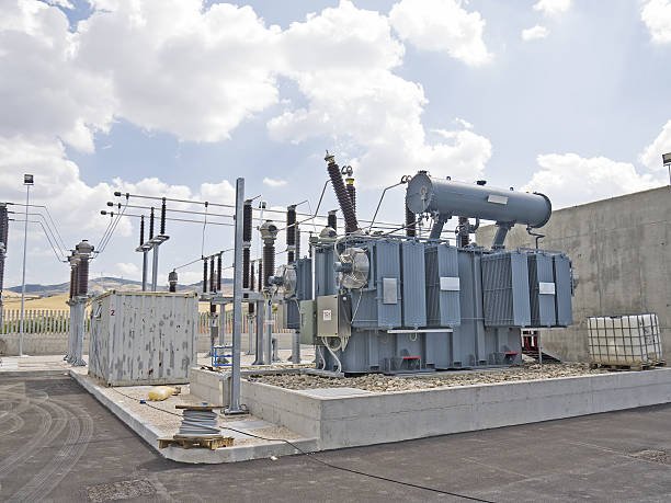
Three-phase power transformers are used only in electrical substations.False
Three-phase power transformers are also widely used in generation plants, industrial facilities, commercial buildings, renewable-energy systems, and other electrical infrastructure.
Where Are Three-Phase Power Transformers Used?
The main applications can be summarized as follows:
| Application | Main Purpose |
|---|---|
| Power generation | Increase generator voltage |
| Transmission | Step voltage up or down |
| Distribution | Reduce voltage for local networks |
| Industrial plants | Supply suitable voltage to equipment |
| Commercial buildings | Provide building distribution voltage |
| Renewable energy | Connect generation equipment to the grid |
| Data centers | Supply reliable electrical power |
| Infrastructure | Support railways, water systems, and utilities |
The same basic transformer principle is used in each application, but the design can be very different.
How Are They Used in Power Generation?
Generators typically produce electricity at a voltage that is not ideal for long-distance transmission. A step-up three-phase power transformer can increase the voltage before electricity enters the transmission network.
For example:
Generator
   ↓
Step-Up Transformer
   ↓
High-Voltage Transmission
   ↓
Transmission Substation
Increasing voltage allows the same power to be transmitted with lower current. Lower current reduces resistive losses in transmission conductors.
Generator step-up transformers therefore need high reliability because a transformer failure can affect a large amount of generating capacity.
Important specifications include rated MVA, generator-side voltage, transmission-side voltage, impedance, insulation level, cooling system, and short-circuit strength.
How Are They Used in Transmission Systems?
Transmission networks move electricity over long distances between generating plants and major load centers. Three-phase power transformers are used at different voltage levels to adapt the system to changing network requirements.
A typical power path may look like:
Generation
   ↓
High-Voltage Step-Up
   ↓
Transmission
   ↓
Grid Substation
   ↓
Step-Down Transformer
   ↓
Distribution
At transmission substations, transformers can reduce high voltage to a lower transmission or sub-transmission voltage.
The transformer impedance is especially important because it influences fault current and voltage regulation. Tap-changing equipment may also be used where system voltage needs continuous or controlled adjustment.
What Is Their Role in Power Distribution?
Distribution is one of the most common applications of three-phase power transformers.
After electricity travels through the transmission network, the voltage must be reduced to levels suitable for local distribution systems. A three-phase transformer performs this voltage conversion efficiently.
Distribution transformers may supply:
- Industrial parks
- Commercial areas
- Apartment complexes
- Hospitals
- Schools
- Office buildings
- Utility networks
The transformer rating should be selected according to present and expected future load. Choosing a transformer that is too small can cause overheating and voltage problems, while excessive oversizing can increase initial cost and no-load energy consumption.
How Are They Used in Industrial Plants?
Industrial facilities often have large three-phase loads, including motors, pumps, compressors, furnaces, welding equipment, production lines, and process equipment.
A three-phase power transformer can convert incoming utility voltage to the voltage required by these systems.
Industrial transformer selection often requires additional attention to:
- Motor starting current
- Nonlinear loads
- Harmonic currents
- Load variation
- Short-circuit conditions
- Voltage regulation
- Indoor or outdoor installation
- Cooling requirements
For example, a factory may receive medium-voltage power from the utility and use a step-down transformer to supply a low-voltage switchboard.
The transformer must be sized for both normal operating load and expected expansion.
How Are Three-Phase Transformers Used in Commercial Buildings?
Large commercial buildings also use three-phase transformers for electrical distribution.
Typical applications include:
- Shopping centers
- Hotels
- Office buildings
- Airports
- Hospitals
- Large warehouses
- Universities
The transformer reduces incoming utility voltage to the building's distribution voltage.
For commercial applications, reliability, noise, installation space, fire considerations, maintenance, and energy efficiency can be particularly important.
Depending on the building and local requirements, either oil-immersed or dry-type transformers may be appropriate.
What Is the Role of Three-Phase Transformers in Renewable Energy?
Solar farms, wind farms, battery-energy-storage systems, and other renewable-energy facilities need transformers to connect electrical equipment to collection networks and the utility grid.
For example:
Solar Panels
    ↓
Inverters
    ↓
Step-Up Transformer
    ↓
Medium/High-Voltage Collection System
    ↓
Grid
Wind turbines follow a similar principle.
Renewable-energy transformers may experience changing power output, frequent switching, harmonics from power electronic converters, and demanding outdoor environmental conditions.
Therefore, the transformer design may need to account for the specific characteristics of the inverter or generator rather than only the nominal MVA rating.
How Are They Used in Data Centers?
Data centers require highly reliable electrical power because unexpected outages can cause major service disruption.
Three-phase transformers can be used between utility supplies, medium-voltage systems, UPS equipment, and low-voltage distribution systems.
Typical considerations include:
- High continuous loading
- Redundant power systems
- Harmonic-producing electronic loads
- Cooling
- Low losses
- Voltage stability
- Space limitations
- Monitoring and protection
For data centers, transformer selection should be coordinated with the complete electrical architecture rather than treated as a standalone purchase.
How Do Transformer Applications Determine Specifications?
Different applications require different transformer designs.
| Requirement | Generation | Transmission | Distribution | Industrial | Renewable |
|---|---|---|---|---|---|
| Capacity | High | High | Medium–high | Application-dependent | Application-dependent |
| Voltage conversion | Usually step-up | Step-up/down | Mainly step-down | Usually step-down | Often step-up |
| Impedance | System-specific | Critical for grid behavior | Important for fault current | Important for equipment | Grid-specific |
| Cooling | Often advanced | Often advanced | Depends on rating | Depends on load | Outdoor conditions often important |
| Harmonics | Usually limited | System-dependent | Load-dependent | Often important | Often important |
| Tap control | May be required | Common in some systems | Common where voltage control is needed | Application-specific | Grid-dependent |
These are general guidelines. The final specification must always be based on the actual electrical system.
What Should Buyers Consider Before Choosing a Three-Phase Power Transformer?
Before ordering, buyers should provide the manufacturer with complete application information.
At minimum, specify:
- Primary voltage
- Secondary voltage
- Rated kVA or MVA
- Frequency
- Three-phase connection
- Vector group
- Transformer impedance
- Tap requirements
- Cooling method
- Insulation level
- Installation environment
- Load characteristics
- Harmonic requirements
- Protection requirements
- Applicable standards
The supplier should then determine the appropriate core, winding, insulation, cooling, tank, bushing, and protection configuration.
Why Are Three-Phase Power Transformers Important?
The main advantage of a three-phase power transformer is its ability to efficiently manage large amounts of electrical power in three-phase systems. From the generator to the transmission network and finally to industrial or commercial loads, transformers make different voltage levels compatible.
The application determines what the transformer must achieve:
Application
    ↓
Voltage + Capacity
    ↓
Winding Connection
    ↓
Impedance + Insulation
    ↓
Cooling + Protection
    ↓
Reliable Transformer Operation
A transformer for a generating station should not automatically be designed the same way as one for a factory or solar farm. Each application has different electrical, thermal, mechanical, and operational requirements.
In conclusion, three-phase power transformers are mainly applied in generation, transmission, distribution, industrial power systems, commercial buildings, renewable-energy projects, data centers, and infrastructure. Their primary job is voltage conversion, but transformer selection also affects efficiency, voltage regulation, fault performance, system compatibility, and long-term reliability.
What Are the Advantages of Three-Phase Power Transformers Compared With Single-Phase Transformers?
When choosing a transformer for a factory, substation, commercial building, or power network, buyers often need to decide between a three-phase power transformer and several single-phase transformers. Using the wrong configuration can increase installation space, equipment cost, losses, and maintenance requirements. The key is to match the transformer type with the actual power system and load rather than assuming that one design is always better.
The main advantages of a three-phase power transformer over single-phase transformers are higher power-transfer capability in a compact structure, better suitability for three-phase systems, lower material and installation requirements for many applications, and easier integration into industrial and grid networks. A three-phase transformer combines the three phases into one coordinated magnetic and electrical system, while three single-phase transformers require separate units and connections.
The comparison becomes clearer when we examine efficiency, size, cost, reliability, installation, maintenance, and application requirements from a practical manufacturing perspective.
Three-phase power transformers are always more efficient than single-phase transformers.False
Three-phase transformers are often advantageous for three-phase power systems, but actual efficiency depends on core design, winding losses, loading, cooling, and operating conditions.
What Are the Main Advantages?
For large three-phase electrical systems, the main benefits can be summarized as follows:
| Advantage | Three-Phase Transformer | Single-Phase Transformers |
|---|---|---|
| Three-phase compatibility | Excellent | Requires multiple units |
| Power capacity | Suitable for high capacity | Better for smaller loads |
| Space | Generally more compact | Requires more individual equipment |
| Installation | One main transformer unit | Multiple units and connections |
| Material use | Efficient integrated design | More duplicated components |
| Maintenance | Centralized | Multiple units to inspect |
| Industrial applications | Excellent | Usually less convenient |
| Grid applications | Widely used | Used where system design requires it |
These advantages are most significant when the electrical system itself is three-phase.
Why Is a Three-Phase Transformer More Compact?
A three-phase transformer integrates three phase windings and their magnetic circuits into one transformer assembly. This avoids having three completely separate transformer tanks, cores, and accessory systems.
A simplified comparison is:
Three-Phase Transformer

      ┌─────────────┐
      │ Core +      │
      │ 3 Windings  │
      └─────────────┘

Three Single-Phase Transformers

   ┌─────┐  ┌─────┐  ┌─────┐
   │Core │  │Core │  │Core │
   │Wind.│  │Wind.│  │Wind.│
   └─────┘  └─────┘  └─────┘
For large installations, the integrated three-phase design can reduce the overall footprint and simplify the arrangement of cables, busbars, and auxiliary equipment.
This is particularly useful in substations and industrial plants where installation space is limited.
How Can Three-Phase Transformers Reduce Equipment Cost?
A three-phase transformer can often use materials more efficiently than three equivalent single-phase units.
With separate single-phase transformers, each unit requires its own:
- Magnetic core
- Tank or enclosure
- Windings
- Insulation system
- Bushings
- Cooling surfaces
- Protection and monitoring components
An integrated three-phase transformer can share parts of the magnetic circuit, tank structure, cooling arrangement, and accessories.
However, this does not mean that every three-phase transformer is automatically cheaper. Transportation, capacity, voltage level, redundancy requirements, and site conditions can change the economics.
For buyers, the better comparison is total installed cost, not simply the purchase price of the transformer.
Why Are Three-Phase Transformers Better Suited to Industrial Loads?
Most large industrial electrical systems use three-phase power. Motors, pumps, compressors, production machinery, and many industrial power systems are designed around three-phase supplies.
A three-phase power transformer can connect directly to these systems without requiring separate single-phase units to recreate the three-phase supply.
This provides a simpler electrical arrangement and can make system design easier.
Industrial buyers should still consider load characteristics, including motor starting, harmonics, load variation, and future expansion.
Are Three-Phase Transformers More Efficient?
Three-phase transformers can provide very good efficiency when correctly designed and loaded. Their integrated magnetic circuit can reduce duplicated material and make efficient use of the core and windings.
However, efficiency depends on several factors:
- Core material
- Core flux density
- Winding resistance
- Conductor size
- Transformer loading
- Cooling
- Operating temperature
- Manufacturing quality
Transformer losses can generally be divided into no-load losses and load losses.
No-load losses are mainly associated with the magnetic core and continue while the transformer is energized. Load losses increase as winding current increases.
Therefore, buyers should compare the manufacturer's guaranteed no-load loss and load loss, rather than assuming a three-phase configuration automatically guarantees higher efficiency.
What About Installation and Maintenance?
One integrated transformer can simplify installation compared with three separate single-phase units.
A three-phase transformer generally requires one main tank, one coordinated cooling system, and a unified set of major accessories.
This can reduce the number of individual components that installation teams need to position and connect.
Maintenance can also be more centralized. Instead of managing three independent transformer bodies, technicians work with one integrated unit.
However, there is an important trade-off: a major failure in one integrated three-phase transformer can affect all three phases. With separate single-phase transformers, a failed unit may sometimes be isolated and replaced while the remaining units continue operating, depending on system design.
Therefore, reliability and redundancy requirements must be considered alongside compactness and cost.
Which Is Better for Large Power Systems?
For high-capacity transmission, distribution, and industrial applications, three-phase transformers are usually the more practical choice because the electrical system itself is three-phase.
Typical applications include:
- Power-generation substations
- Transmission substations
- Utility distribution
- Industrial plants
- Commercial complexes
- Renewable-energy projects
- Large infrastructure facilities
- Data centers
Single-phase transformers remain useful for smaller loads, residential applications, special equipment, and systems where independent phase operation or redundancy is important.
How Do the Two Configurations Compare for Buyers?
The following checklist provides a simple way to make the decision:
| Buyer Requirement | Preferred Option |
|---|---|
| Large three-phase load | Three-phase |
| Industrial motor loads | Three-phase |
| High MVA application | Three-phase |
| Limited installation space | Usually three-phase |
| Simple three-phase grid connection | Three-phase |
| Small individual load | Single-phase |
| Independent phase replacement | Single-phase units may help |
| Strong phase-level redundancy | Single-phase units may be considered |
| Residential small-load application | Usually single-phase |
| Centralized equipment design | Three-phase |
The final decision should be based on the complete electrical system.
What Should Buyers Check Before Choosing a Three-Phase Power Transformer?
A transformer should be selected according to actual operating requirements. Important specifications include:
- Primary and secondary voltage
- Rated kVA or MVA
- Frequency
- Vector group
- Winding connection
- Transformer impedance
- Tap range
- Insulation level
- Cooling method
- No-load loss
- Load loss
- Installation environment
- Short-circuit requirements
- Harmonic loading
- Required protection and monitoring
For large transformers, transportation and installation should also be considered. A very large integrated transformer may require special transportation equipment, lifting arrangements, and site preparation.
From a manufacturer's perspective, the best transformer is not simply the smallest or cheapest option. It is the design that provides the required electrical performance with reasonable lifecycle cost and reliable operation.
Why Choose a Three-Phase Power Transformer?
The biggest advantage of a three-phase power transformer is that it is designed specifically for three-phase electrical systems. It can provide high power capacity in a relatively compact package while integrating the core, windings, insulation, cooling, and protection systems into one coordinated unit.
Compared with three separate single-phase transformers, it can often reduce duplicated components, simplify installation, and provide a more compact solution.
Nevertheless, separate single-phase transformers can still be the better choice where redundancy, transportation, phase independence, or special operating requirements are important.
In short, three-phase transformers are generally preferred for large industrial, transmission, distribution, and commercial three-phase systems, while single-phase transformers remain valuable for smaller or specialized applications.
How Should Buyers Select the Right Three-Phase Power Transformer?
Choosing the wrong three-phase power transformer can cause voltage problems, unnecessary losses, overheating, poor voltage regulation, difficult installation, and higher lifecycle costs. A transformer that looks suitable from its kVA/MVA rating alone may still be unsuitable because of voltage level, vector group, impedance, cooling, insulation, harmonics, or site conditions. The practical solution is to evaluate the transformer as part of the complete electrical system, not as an isolated piece of equipment.
Buyers should select the right three-phase power transformer by first defining primary and secondary voltage, rated kVA/MVA capacity, frequency, vector group, impedance, insulation level, tap requirements, cooling method, installation environment, load characteristics, efficiency targets, and applicable standards. The selected transformer should provide adequate capacity for the present load and planned expansion while meeting required electrical, thermal, mechanical, safety, and testing requirements.
The following guide provides a practical selection process that buyers can use when comparing transformer manufacturers and quotations.
A transformer can be selected correctly based only on its rated kVA or MVA capacity.False
Capacity is important, but correct selection also requires voltage, frequency, vector group, impedance, insulation, cooling, load characteristics, installation conditions, and other electrical and mechanical requirements.
1. Start With the Electrical System
The first step is to identify where the three-phase power transformer will operate.
For example, a transformer connecting a medium-voltage utility system to an industrial low-voltage network has very different requirements from a generator step-up transformer or a renewable-energy transformer.
Prepare these basic parameters before requesting quotations:
| Parameter | What Buyers Should Define |
|---|---|
| Primary voltage | Nominal and maximum system voltage |
| Secondary voltage | Required output voltage |
| Capacity | kVA or MVA |
| Frequency | 50 Hz, 60 Hz, or project-specific |
| Phase | Three-phase |
| Connection | Delta, star/wye, etc. |
| Vector group | Required phase displacement |
| Impedance | Required percentage impedance |
| Taps | Off-circuit or on-load tap requirements |
| Cooling | ONAN, ONAF, dry-type, etc. |
| Installation | Indoor, outdoor, enclosed, substation |
| Environment | Temperature, altitude, humidity, pollution |
This information prevents manufacturers from making assumptions that can lead to an unsuitable design.
2. How Should Buyers Choose Transformer Capacity?
The rated capacity should cover the expected maximum operating load without unnecessarily oversizing the transformer.
A simple starting point is:
Required transformer capacity ≈ maximum demand × future-growth allowance
But the actual engineering calculation should consider load diversity, motor starting, continuous loading, ambient temperature, harmonics, and permissible overload.
For example, if the calculated maximum demand is 1,600 kVA, a buyer should not automatically order a 1,600 kVA transformer. A reasonable engineering margin may justify a higher rating, depending on the project.
At the same time, excessive oversizing can be undesirable because the transformer may spend much of its life lightly loaded while its core continues to produce no-load losses.
3. Why Are Primary and Secondary Voltages Critical?
The transformer must match the actual system voltage.
For a step-down application:
Medium Voltage
     │
     ▼
┌───────────────┐
│ 3-Phase       │
│ Transformer   │
└───────────────┘
     │
     ▼
Low Voltage
Industrial Loads
Buyers should distinguish between nominal voltage and the transformer's actual rated voltage and insulation requirements.
The voltage specification should also account for expected system variation and tap-changer requirements. If the incoming voltage changes significantly, an appropriate tap range may be necessary to maintain acceptable secondary voltage.
4. How Should Buyers Select the Vector Group?
The vector group is not simply a catalog preference. It defines the relationship between the primary and secondary winding connections and their phase displacement.
For example, common configurations include combinations such as Dyn11, depending on the system design.
The vector group can affect:
- Parallel operation
- Phase displacement
- Grounding behavior
- Harmonic performance
- Protection coordination
- System fault characteristics
Two transformers intended to operate in parallel must have compatible electrical characteristics, including suitable voltage ratio, impedance, polarity, phase sequence, and vector group.
Therefore, buyers should obtain the required vector group from the electrical engineer or system designer before ordering.
5. How Important Is Transformer Impedance?
Transformer impedance affects short-circuit current and voltage regulation.
A higher impedance can limit fault current, but it can also increase voltage drop under load. A lower impedance may improve voltage regulation while allowing higher fault current.
Therefore, the correct impedance is a system-design parameter, not something buyers should select only by comparing prices.
| Selection Factor | Lower Impedance | Higher Impedance |
|---|---|---|
| Voltage regulation | Generally better | Generally poorer |
| Fault current | Higher | Lower |
| Voltage drop | Lower | Higher |
| Parallel operation | Must be carefully matched | Must be carefully matched |
| Protection design | Higher fault duty | Lower fault duty |
The manufacturer's guaranteed impedance should be checked against the project's electrical study.
6. Should Buyers Choose Oil-Immersed or Dry-Type?
The choice depends heavily on installation and safety requirements.
Oil-immersed three-phase power transformers are commonly attractive for outdoor substations and larger power ratings because liquid insulation and cooling can support high-capacity designs.
Dry-type transformers can be advantageous indoors or where liquid containment and fire-related considerations make a dry design preferable.
A simplified comparison is:
| Requirement | Oil-Immersed | Dry-Type |
|---|---|---|
| Large outdoor substations | Excellent | Less common |
| Indoor installation | Possible with proper provisions | Often suitable |
| Large capacity | Excellent | Available but application-dependent |
| Liquid containment | Required | Not applicable |
| Fire considerations | Must be addressed | Often favorable |
| Cooling | Strong thermal capability | Air-based |
| Maintenance | Oil condition may require attention | No insulating liquid |
The correct choice should consider local regulations, fire protection, ventilation, environmental conditions, and total lifecycle cost.
7. How Should Cooling Be Selected?
Cooling directly affects transformer thermal performance and permissible loading.
Depending on the transformer design, cooling may use natural oil and air circulation or forced cooling systems.
For an oil-immersed transformer, typical designations include:
- ONAN — Oil Natural Air Natural
- ONAF — Oil Natural Air Forced
The required cooling method depends on rated capacity, load profile, ambient temperature, enclosure conditions, and expected operating margin.
A transformer manufacturer should provide temperature-rise guarantees and clearly define the cooling arrangement rather than simply stating that the transformer has a "high-efficiency cooling system."
8. How Do Load Characteristics Affect Selection?
Two loads with the same apparent power can produce very different transformer stresses.
Buyers should identify:
- Motor loads
- Variable-frequency drives
- Rectifiers
- UPS systems
- Data-center loads
- Welding equipment
- Renewable-energy converters
- Nonlinear electronic loads
Harmonic-producing equipment can increase additional heating in windings and structural components. For these applications, transformer design may require special attention to harmonic currents and thermal capability.
Motor-heavy systems may also require consideration of starting current and voltage dips.
9. What About Efficiency and Transformer Losses?
Do not compare transformers only by purchase price.
A better evaluation includes:
Total cost = purchase cost + installation cost + energy losses + maintenance + expected service-life costs
Transformer losses are commonly divided into no-load and load losses.
No-load loss occurs whenever the transformer is energized, while load loss changes with current. Therefore, a transformer operating continuously can accumulate significant energy costs from relatively small differences in guaranteed losses.
When comparing manufacturers, request guaranteed values for:
| Test Item | Why It Matters |
|---|---|
| No-load loss | Continuous energy consumption |
| Load loss | Efficiency under load |
| Impedance | Fault current and voltage regulation |
| Temperature rise | Thermal performance |
| Dielectric tests | Insulation integrity |
| Ratio test | Correct voltage transformation |
| Winding resistance | Winding and connection verification |
10. What Factory Quality Should Buyers Verify?
A professional transformer supplier should be able to demonstrate a controlled manufacturing and testing process.
Buyers should examine:
- Core cutting and stacking equipment
- Winding machines
- Vacuum drying equipment
- Oil treatment equipment
- Tank fabrication
- Controlled assembly areas
- Electrical testing facilities
- Temperature and process records
- Quality-control procedures
- Routine and type-test capabilities
Important factory tests can include winding resistance, voltage ratio, polarity or vector-group verification, dielectric tests, no-load loss, load loss, impedance, and other tests specified by the applicable project standard.
A strong supplier should provide test reports and clear acceptance criteria rather than relying only on a general quality certificate.
11. What Is the Best Selection Checklist?
Before placing an order, buyers can use this checklist:
| Question | Confirmed? |
|---|---|
| Primary voltage defined? | ☐ |
| Secondary voltage defined? | ☐ |
| kVA/MVA capacity calculated? | ☐ |
| Future load considered? | ☐ |
| 50/60 Hz confirmed? | ☐ |
| Vector group confirmed? | ☐ |
| Impedance specified? | ☐ |
| Tap range defined? | ☐ |
| Cooling method suitable? | ☐ |
| Oil or dry-type selected appropriately? | ☐ |
| Harmonic load evaluated? | ☐ |
| Ambient temperature considered? | ☐ |
| Insulation level confirmed? | ☐ |
| Installation environment defined? | ☐ |
| Guaranteed losses compared? | ☐ |
| Factory testing verified? | ☐ |
| Delivery and transportation planned? | ☐ |
Conclusion
A three-phase power transformer transfers electrical energy between three-phase circuits while stepping voltage up or down through electromagnetic induction. Its three-phase winding arrangement and magnetic-core design allow it to provide efficient and balanced power transformation for high-capacity electrical systems. For buyers, factors such as rated capacity, voltage ratio, winding connection, vector group, impedance, insulation level, cooling method, efficiency, and installation conditions should be evaluated together.
FAQ
Q1: What is a three-phase power transformer and how does it work?
A1: A three-phase power transformer is an electrical device designed to transfer electrical energy between three-phase circuits while changing voltage and current levels. It uses electromagnetic induction to transfer energy between windings through a shared magnetic field.
A typical three-phase transformer has primary and secondary windings associated with the three phases of an electrical system. Depending on the design, these windings may be arranged around a common magnetic core or incorporated into separate magnetic circuits. The windings are electrically connected according to the required transformer configuration.
When three-phase alternating voltage is applied to the primary side, it produces changing magnetic flux in the transformer core. This changing flux induces voltage in the secondary windings. The relationship between the primary and secondary winding turns determines whether the transformer increases or decreases voltage.
Three-phase transformers are particularly useful because modern industrial and utility power systems commonly distribute electricity using three phases. A single transformer can therefore handle three-phase power in a coordinated package, providing a compact and practical solution for substations, industrial facilities, renewable-energy projects, commercial infrastructure, and other high-power applications.
The transformer does not create electrical energy. Instead, it changes electrical characteristics while transferring power from one circuit to another. In an ideal transformer, input and output power are approximately equal, while a real transformer experiences losses caused by winding resistance, core effects, leakage flux, and other physical factors.
The connections between the windings are also important. Common configurations include delta and wye arrangements. These configurations influence voltage relationships, neutral availability, grounding arrangements, phase displacement, and system behavior.
A three-phase power transformer must be specified according to the requirements of the electrical system. Important parameters include rated power, primary and secondary voltage, frequency, impedance, insulation level, cooling method, temperature rise, tap configuration, and installation conditions.
Compared with using three independent single-phase transformers, a three-phase transformer can provide a more integrated design. However, the best solution depends on transportation, maintenance, redundancy, installation requirements, and project-specific considerations.
In simple terms, a three-phase power transformer uses electromagnetic induction to transfer three-phase electrical energy between circuits while providing the required voltage transformation and electrical isolation.
Q2: What are the main types of three-phase power transformers?
A2: Three-phase power transformers can be classified in several ways, including construction, winding arrangement, insulation system, cooling method, and application. There is no single classification that describes every transformer, so buyers should consider several characteristics together.
One common distinction is between oil-immersed and dry-type three-phase transformers. Oil-immersed transformers use insulating liquid for electrical insulation and heat transfer. They are widely used in substations, utility networks, industrial installations, and high-capacity applications. Dry-type transformers use solid insulation and air-based cooling without insulating oil, making them attractive for many indoor and specialized installations.
Three-phase transformers can also be classified according to their winding connections. Delta-delta, wye-wye, delta-wye, and wye-delta configurations are commonly encountered. Each arrangement provides different electrical characteristics and may be selected according to system voltage, grounding, neutral requirements, and phase relationships.
Another classification is based on voltage function. Step-up transformers increase voltage and are commonly used between generating facilities and higher-voltage networks. Step-down transformers reduce voltage for distribution or industrial applications.
Transformers can also differ according to their winding structure. Two-winding transformers have a primary and secondary winding system, while multi-winding transformers may provide several voltage outputs or serve more complex electrical arrangements. Autotransformer configurations use a shared portion of the winding and can be useful when the voltage ratio is relatively close.
Cooling classification is also important. Depending on capacity and design, three-phase transformers may use natural or forced cooling arrangements. The cooling system must be capable of managing heat produced by core and winding losses under expected operating conditions.
Application-specific transformers represent another major category. Generator transformers, substation transformers, industrial transformers, renewable-energy transformers, and specialized grid transformers can have significantly different specifications even when they share a three-phase configuration.
When comparing transformer types, buyers should avoid selecting equipment based only on the label “three-phase.” The transformer must match the required capacity, voltage, frequency, insulation, impedance, cooling, environmental conditions, and installation arrangement.
The correct type is therefore determined by the complete electrical and physical requirements of the project. A clear technical specification allows manufacturers to recommend a suitable three-phase transformer configuration instead of relying on a generic product category.
Q3: What are the advantages of using a three-phase power transformer?
A3: Three-phase power transformers offer several advantages for electrical systems that use three-phase power. Their integrated construction, efficient power transfer, and suitability for high-capacity applications make them widely used in utility, industrial, commercial, and infrastructure projects.
One major advantage is that a three-phase transformer can handle all three phases within one coordinated transformer assembly. This can simplify the physical arrangement compared with installing three independent single-phase transformers.
Space efficiency can also be important. A properly designed three-phase transformer may require less installation space than an equivalent bank of separate transformers, although the actual dimensions depend on capacity, cooling equipment, enclosure design, accessories, and manufacturer construction.
Three-phase systems are widely used for industrial loads and power transmission because they provide an effective method of delivering substantial electrical power. A three-phase transformer therefore integrates naturally with motors, industrial equipment, substations, distribution systems, and other three-phase loads.
Another benefit is coordinated voltage transformation. The three phases are transformed within the same electrical system, maintaining the required phase relationships when the transformer is correctly designed and connected.
Three-phase transformers can also provide good operational efficiency. Modern designs use optimized magnetic cores, conductors, insulation systems, and cooling arrangements to reduce losses while maintaining reliable performance.
Installation and maintenance requirements can sometimes be simplified because one transformer assembly contains the three-phase transformation system. However, this also means that a major transformer failure can affect all three phases at once, so system designers need to consider redundancy and contingency requirements.
Three-phase transformers are also available in many configurations. Buyers can select different winding connections, voltage ratios, cooling methods, insulation systems, tap arrangements, and construction types to match the application.
For utility and industrial projects, another advantage is scalability. Manufacturers can design three-phase transformers for a wide range of power ratings and voltage levels, allowing the technology to be used from relatively modest installations to large electrical substations.
The benefits should nevertheless be evaluated against project-specific factors. Transportation, lifting requirements, spare-transformer strategy, accessibility, fault consequences, and maintenance planning may influence whether a single three-phase transformer or a bank of single-phase units is more appropriate.
Overall, the principal advantages are integrated three-phase operation, efficient power transformation, compact system design, broad application suitability, and flexible configuration. These characteristics explain why three-phase transformers are a standard solution for many modern electrical power systems.
Q4: Where are three-phase power transformers commonly used?
A4: Three-phase power transformers are commonly used wherever electrical systems need to transfer or transform substantial amounts of three-phase power. Major applications include power generation, transmission, substations, industrial facilities, commercial buildings, renewable-energy projects, and large infrastructure systems.
In power generation, transformers can connect generating equipment to transmission networks by increasing the generator voltage to a higher level. This allows electrical power to enter the transmission system at an appropriate voltage.
Transmission and substation networks use three-phase transformers to change voltage between different levels. A transmission system may require several voltage transformations as electricity moves from generation facilities through the grid and toward distribution networks.
Industrial facilities are another important application. Manufacturing plants, processing facilities, mining operations, chemical plants, and large machinery installations often use three-phase electrical systems. Transformers can provide the voltage levels required by industrial equipment while helping separate different parts of the electrical system.
Commercial facilities may also use three-phase transformers for building power distribution. Large office complexes, shopping centers, data centers, hospitals, transportation facilities, and other high-demand buildings can require substantial three-phase electrical capacity.
Renewable-energy installations increasingly rely on three-phase transformers as well. Solar power plants, wind farms, battery-energy projects, and other power-generation systems may use transformers to connect power-conversion equipment to collection networks or utility grids.
Three-phase transformers can also be found in infrastructure projects such as rail systems, water-treatment facilities, airports, and large public utilities. The exact transformer specification depends on the electrical architecture and load characteristics of each installation.
The transformer's location within the electrical network determines many of its design requirements. A generator transformer may have different voltage, insulation, and operating requirements from an industrial plant transformer. Similarly, a renewable-energy transformer may need to accommodate variable power flows and specific grid-connection requirements.
Environmental conditions are also important. Outdoor substations may require equipment designed for weather exposure, while indoor installations may place greater emphasis on ventilation, fire considerations, noise, and physical access.
When purchasing a three-phase power transformer, buyers should therefore provide application details rather than only specifying a desired power rating. Information about source voltage, load voltage, capacity, frequency, installation environment, load profile, grounding, and system protection helps manufacturers determine the appropriate design.
Because three-phase transformers serve such a wide range of applications, there is no universal configuration. The correct transformer must be engineered around the electrical system in which it will operate.
References
IEC 60076-1 — Power Transformers: General
https://webstore.iec.ch/en/publication/588
IEC 60076-2 — Power Transformers: Temperature Rise
https://webstore.iec.ch/en/publication/604
IEC 60076-3 — Power Transformers: Insulation Levels and Tests
https://webstore.iec.ch/en/publication/605
IEC 60076-5 — Power Transformers: Ability to Withstand Short Circuit
https://webstore.iec.ch/en/publication/607
IEC 60076-7 — Loading Guide for Mineral-Oil-Immersed Power Transformers
https://webstore.iec.ch/en/publication/608
IEEE C57.12.00 — General Requirements for Liquid-Immersed Transformers
https://standards.ieee.org/ieee/C57.12.00/6962/
IEEE C57.12.01 — General Requirements for Dry-Type Transformers
https://standards.ieee.org/ieee/C57.12.01/6775/
IEEE C57.12.80 — Terminology for Power and Distribution Transformers
https://standards.ieee.org/ieee/C57.12.80/7006/
IEEE Technology Navigator — Power Transformers
https://technav.ieee.org/topic/power-transformers/
U.S. Department of Energy — Electricity Delivery and Grid Systems
https://www.energy.gov/oe