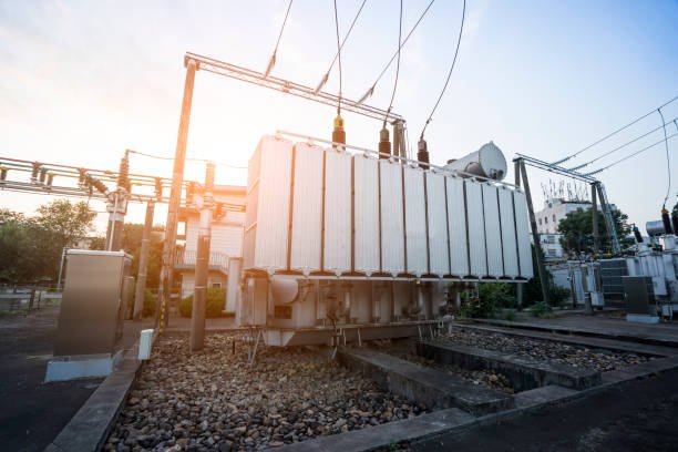
Electrical power systems require a reliable grounding reference to control phase-to-ground voltages, support protective device operation, and reduce the risk of equipment damage during ground faults. However, some three-phase systems, particularly ungrounded or delta-connected networks, do not provide a suitable neutral point for grounding. Without an appropriate grounding arrangement, ground faults can cause dangerous overvoltages, insulation stress, and unreliable fault detection. Understanding the function of a grounding transformer helps engineers and buyers determine when it is necessary and how to specify it correctly.
A grounding transformer is an electrical transformer used to establish a neutral grounding point in a three-phase power system that otherwise lacks a suitable neutral connection. It commonly uses a zigzag or grounded-wye/delta winding configuration to provide a path for zero-sequence current during ground faults. When designed with an appropriate grounding impedance, it helps control phase-to-ground voltages and enables ground-fault protection to operate correctly. Grounding transformers are commonly used in delta-connected networks, industrial power systems, renewable-energy installations, and substations where a defined grounding reference is required.
Selecting a grounding transformer requires more than identifying the system voltage. Engineers and buyers must consider the grounding method, expected ground-fault current, fault duration, system configuration, and protection scheme to ensure the transformer performs its intended function safely and reliably.
What Is a Grounding Transformer and How Does a Grounding Transformer Work?
In an ungrounded or delta-connected three-phase power system, a single line-to-ground fault can be difficult to detect and may cause dangerous overvoltages on the healthy phases. Without a defined grounding point, protection devices may not respond as expected, increasing the risk of insulation damage, equipment failure, and unplanned downtime. A grounding transformer provides a practical solution by establishing a neutral point and creating a controlled path for ground-fault current.
A grounding transformer is a transformer designed to provide a neutral point for grounding a three-phase electrical system that otherwise has no suitable neutral. It is commonly connected in zigzag or grounded-wye/delta configuration and may work with a neutral grounding resistor or reactor to limit ground-fault current and support reliable protection.
Understanding how a grounding transformer works helps engineers select the correct connection, grounding impedance, and rating for their power distribution system. The right design improves fault detection, protects equipment, and supports safer, more reliable operation.
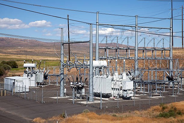
What Is a Grounding Transformer?
A grounding transformer, also called an earthing transformer, is used to establish an artificial neutral point in a three-phase electrical network. It is especially useful in systems where the transformer or generator connection does not naturally provide a neutral, such as a delta-connected system.
The neutral point can then be connected directly to earth or through an impedance. This allows the system designer to control ground-fault current and establish predictable conditions for protective relays.
Grounding transformers are commonly used in:
- Medium-voltage distribution networks
- Industrial power systems
- Renewable energy installations
- Collector systems for wind and solar farms
- Delta-connected transformer networks
- Systems requiring a defined ground-fault protection scheme
A grounding transformer is not normally intended to supply continuous power to ordinary loads. Its primary purpose is grounding and fault management, so its rating and thermal design must reflect the expected ground-fault current and duration.
How Does a Grounding Transformer Work?
A grounding transformer works by creating a neutral reference for a three-phase system. During normal operation, the three phase voltages remain balanced, and the transformer carries only the current associated with the system's normal unbalance and other design-specific conditions.
When a phase-to-ground fault occurs, the grounding transformer provides a path for zero-sequence current. This allows ground-fault current to flow through the grounding arrangement, helping protective relays detect the fault and initiate isolation.
The basic process is:
- Establish a neutral point: The transformer is connected to the three-phase network and forms an artificial neutral.
- Provide a fault-current path: During a ground fault, current can return through the grounding connection.
- Control current magnitude: A neutral grounding resistor (NGR) or reactor may be connected between the neutral and earth.
- Support protection: Relays and other protective devices detect the resulting fault current or voltage and operate according to their settings.
- Reduce damage risk: Properly designed grounding helps limit electrical and thermal stress during the fault.
A grounding transformer does not eliminate ground faults. It helps make the fault behavior more predictable and allows the protection system to respond appropriately.
Main Types of Grounding Transformers
The two most common configurations are zigzag and grounded-wye/delta. The best option depends on the system voltage, grounding requirements, fault-current target, and network design.
| Feature | Zigzag grounding transformer | Grounded-wye/delta grounding transformer |
|---|---|---|
| Winding arrangement | Specially interconnected windings on each phase | Grounded-wye primary with delta-connected secondary |
| Main purpose | Creates a neutral point for grounding | Creates a neutral point and uses a delta winding to accommodate internal circulating components |
| Typical use | Grounding delta-connected systems | Grounding applications where this winding arrangement suits the system design |
| Design considerations | Zero-sequence impedance, thermal duty, and system compatibility | Winding ratings, zero-sequence behavior, and thermal duty |
| Selection priority | Compact grounding arrangement and suitable system impedance | Suitability of the winding configuration and grounding duty |
Zigzag Grounding Transformer
A zigzag grounding transformer uses interconnected windings arranged so that the phase windings provide a neutral point while presenting an appropriate impedance to zero-sequence current. Under balanced normal conditions, the magnetic effects of the phase currents largely cancel. During a ground fault, the winding arrangement provides a path for the zero-sequence current.
Zigzag units are often selected when a dedicated grounding transformer is required without a separate conventional secondary load winding.
Grounded-Wye/Delta Grounding Transformer
This design uses a grounded-wye winding connected to the three-phase system and a delta-connected winding. The delta winding provides a path for circulating components associated with unbalanced and zero-sequence conditions, depending on the design.
The grounded-wye/delta arrangement may be suitable where its winding configuration and electrical characteristics match the grounding scheme. Engineers should verify the manufacturer's zero-sequence impedance data and fault-duty ratings before selection.
What Is the Role of a Neutral Grounding Resistor?
A neutral grounding resistor is often connected between the grounding transformer's neutral point and earth. Its purpose is to limit ground-fault current to a selected value.
Without appropriate impedance, fault current may become high enough to cause severe thermal damage, arc-flash hazards, or mechanical stress. With a properly designed resistor, the system can maintain enough current for dependable fault detection while limiting the energy released during the fault.
The approximate resistive relationship is:
[\RN \approx \frac{V\{LN}}{I_G}]
Where:
- (R_N) = neutral grounding resistance in ohms
- (V_{LN}) = line-to-neutral voltage in volts
- (I_G) = target ground-fault current in amperes
This simplified equation assumes the line-to-neutral voltage is applied across the resistor and that other impedance effects are negligible. Actual grounding design must account for the complete zero-sequence network, system capacitance, transformer impedance, and fault conditions.
| Grounding method | Main characteristic | Important consideration |
|---|---|---|
| Solid grounding | Low-impedance neutral-to-earth connection | Ground-fault current may be high |
| Resistance grounding | Uses a resistor to limit fault current | Resistor current and time ratings must match the protection scheme |
| Reactance grounding | Uses a reactor to limit fault current | Reactance and system behavior require engineering analysis |
| Ungrounded system | No intentional neutral grounding connection | Ground faults can produce abnormal phase-to-ground voltages |
A grounding transformer always eliminates ground faults in a three-phase electrical system.False
A grounding transformer does not prevent or eliminate faults. It establishes a neutral reference and a path for ground-fault current so that the grounding and protection systems can respond as designed.
How to Select the Right Grounding Transformer
Choosing a grounding transformer requires more than matching the system voltage. Engineers must evaluate the electrical network, the expected fault current, the required fault duration, and the protective devices.
1. Confirm System Voltage and Configuration
Identify the nominal line-to-line voltage, system frequency, and existing winding connections. Confirm whether the network lacks a usable neutral and whether the proposed transformer connection is compatible with the system's grounding objectives.
2. Determine Ground-Fault Current
Establish the target ground-fault current based on the system study and protection philosophy. The grounding transformer and any neutral grounding resistor or reactor must withstand the specified current for the required duration.
3. Check Thermal and Short-Time Ratings
Grounding transformers are often rated for short-time duty rather than continuous full-load service. The required duty may be specified in seconds, so the manufacturer's thermal rating and fault withstand capability must match the actual protection-clearing time and system requirements.
4. Verify Zero-Sequence Impedance
Zero-sequence impedance affects the ground-fault current and the behavior of the system during an earth fault. Use manufacturer test data and engineering calculations to confirm the expected performance.
5. Review Standards and Factory Tests
Ask the supplier to identify the applicable standards and provide relevant factory test documentation. Depending on the application and contract, this may include winding resistance, turns ratio, insulation tests, impedance information, routine test reports, and other specified checks.
Common Applications of Grounding Transformers
Grounding transformers are widely used where the electrical system requires a defined neutral point but does not provide one directly.
| Application | Why a grounding transformer is used |
|---|---|
| Industrial distribution | Establishes a grounding reference for delta-connected networks |
| Wind farms | Provides grounding for medium-voltage collector systems where required |
| Solar power plants | Supports grounding and ground-fault protection in compatible collector networks |
| Utility substations | Helps implement the grounding and protection philosophy of selected networks |
| Specialized industrial networks | Provides a neutral point when the existing system connection lacks one |
The actual suitability of a grounding transformer depends on the network configuration and grounding study. Not every delta-connected or renewable energy system requires a separate grounding transformer.
Installation and Maintenance Considerations
A grounding transformer should be installed and commissioned by qualified electrical personnel following the approved design, local regulations, and manufacturer's instructions.
Key checks include:
- Verify phase sequence, terminal identification, and winding connections.
- Confirm the neutral-to-earth connection and grounding conductor sizing.
- Inspect the neutral grounding resistor or reactor, where fitted.
- Verify protective relay settings and trip logic.
- Check enclosure grounding, ventilation, clearances, and environmental suitability.
- Review commissioning test results and keep records for future maintenance.
Maintenance frequency depends on the installation environment, equipment condition, fault history, and manufacturer recommendations. Periodic inspection should include terminals, insulation condition, corrosion, grounding connections, and the condition of associated grounding equipment.
Why Is a Grounding Transformer Needed in Three-Phase Power Systems?
Three-phase power systems often use delta-connected transformers or other configurations without an accessible neutral point. When a line-to-ground fault occurs in an ungrounded system, fault current may be too small or difficult to detect reliably, while the healthy phases can experience increased phase-to-ground voltage. These conditions can complicate protection and place additional stress on insulation. A grounding transformer helps address this problem by providing an artificial neutral point and a defined path for ground-fault current.
A grounding transformer is needed in a three-phase power system when the network requires a neutral grounding point but does not have a suitable neutral available. It provides a path for zero-sequence ground-fault current, supports protective relay operation, and can work with a neutral grounding resistor or reactor to control fault current and reduce equipment damage.
However, a grounding transformer is not required in every three-phase system. Its necessity depends on the network configuration, grounding philosophy, fault-current requirements, and protection design. Understanding these factors helps engineers choose a safe, reliable, and cost-effective grounding solution.
What Is the Main Purpose of a Grounding Transformer?
The main purpose of a grounding transformer is to establish a neutral point for a three-phase system that does not naturally provide one.
In a grounded-wye system, the neutral is available for grounding. In a delta-connected system, however, there is usually no neutral terminal that can be directly grounded. If the system design requires a grounded reference, a grounding transformer can create one without changing the main power transformer's basic connection.
A grounding transformer typically serves three functions:
- Establishes a neutral point: Provides a defined connection between the three-phase network and the grounding system.
- Provides a ground-fault current path: Allows zero-sequence current to flow during a line-to-ground fault.
- Supports protective devices: Helps relays and other protection equipment identify faults and initiate the required response.
The transformer is generally designed for grounding duty rather than continuous supply of ordinary loads. Its short-time current and thermal ratings must match the expected fault current and clearing time.
Why Is Grounding Important in Three-Phase Power Systems?
Grounding affects system voltage behavior, fault detection, and equipment protection. Without a suitable grounding arrangement, the system's response to a ground fault may be less predictable.
1. To Provide a Reference to Earth
Grounding establishes a reference between the electrical system and earth. In an appropriate grounded system, phase-to-ground voltages behave more predictably during normal operation and specified fault conditions.
In an ungrounded system, a single line-to-ground fault can shift the system's neutral potential. Depending on the network and its capacitance, the healthy phases may experience increased phase-to-ground voltage, potentially stressing insulation.
2. To Improve Ground-Fault Detection
Ground-fault current provides information that protective relays can use to detect an abnormal condition. In some ungrounded systems, the current associated with a single ground fault may be limited by system capacitance, making detection more challenging.
A grounding transformer creates a defined zero-sequence path. When designed with suitable grounding impedance and protection settings, this helps the system generate a detectable fault condition.
3. To Limit Equipment Damage
Ground faults can cause overheating, insulation damage, and dangerous arcing. A grounding transformer combined with a properly selected neutral grounding resistor or reactor can limit fault current while allowing protection to operate.
Grounding does not prevent all faults or eliminate all hazards. Correct impedance selection, protective relay coordination, and appropriate equipment ratings remain essential.
How Does a Grounding Transformer Work During a Ground Fault?
During balanced normal operation, the three phase currents sum to approximately zero under ideal conditions. When a phase-to-ground fault occurs, the current balance changes, and zero-sequence current may flow through the grounding transformer and grounding network.
A simplified fault sequence is:
- A phase conductor contacts earth or a grounded structure.
- The system's grounding arrangement provides a return path for fault current.
- The grounding transformer carries the zero-sequence component associated with the fault.
- A neutral grounding resistor or reactor, if installed, helps determine the fault-current magnitude.
- Protective relays detect the fault and initiate an alarm or trip according to the protection scheme.
The actual fault current depends on system voltage, transformer impedance, grounding impedance, network capacitance, and the fault location. Engineers should use a system study rather than relying on the grounding transformer alone to predict the current.
Which Grounding Transformer Configuration Is Suitable?
The two common configurations are zigzag and grounded-wye/delta. The correct choice depends on the electrical network and the required grounding characteristics.
| Comparison | Zigzag grounding transformer | Grounded-wye/delta grounding transformer |
|---|---|---|
| Primary purpose | Establishes a neutral point and provides a zero-sequence path | Establishes a neutral point using a grounded-wye winding |
| Winding arrangement | Specially interconnected windings | Grounded-wye winding with a delta-connected winding |
| Common application | Grounding delta-connected systems | Grounding networks where this winding arrangement meets the design requirements |
| Key design factor | Zero-sequence impedance and thermal duty | Winding ratings, zero-sequence behavior, and thermal duty |
| Selection approach | Verify compatibility with the network and fault-current target | Verify winding configuration and grounding performance through engineering calculations |
Both configurations can be suitable for grounding applications, but neither should be selected by name alone. The manufacturer’s impedance data, connection diagram, and short-time rating must be checked against the system design.
Is a Neutral Grounding Resistor Always Required?
No. A grounding transformer can be connected to earth directly or through an impedance, depending on the system grounding philosophy. A neutral grounding resistor (NGR) is common when the design requires controlled resistive grounding.
The resistor limits ground-fault current while allowing sufficient current for the protection system to detect the fault. A reactor may be used where reactance grounding is appropriate.
For a simplified resistive grounding arrangement, the initial estimate is:
[\RN \approx \frac{V\{LN}}{I_G}]
Where:
- (R_N) is the neutral grounding resistance in ohms.
- (V_{LN}) is the line-to-neutral voltage in volts.
- (I_G) is the target ground-fault current in amperes.
This estimate assumes the voltage is applied across the resistor and neglects other network impedances. Final selection must account for the complete zero-sequence network, system capacitance, fault duration, and relay requirements.
| Grounding arrangement | Main characteristic | Important consideration |
|---|---|---|
| Solid grounding | Provides a low-impedance ground connection | Ground-fault current can be high |
| Resistance grounding | Limits fault current through a resistor | Current and time ratings must match the protection scheme |
| Reactance grounding | Uses a reactor to limit fault current | System impedance and fault behavior require calculation |
| Ungrounded system | Has no intentional neutral-to-earth connection | Ground-fault detection and temporary overvoltages require careful evaluation |
Every three-phase power system needs a separate grounding transformer.False
A separate grounding transformer is only needed when the system requires a neutral grounding point that is not otherwise available. Grounded-wye systems and other suitable configurations may already provide the required neutral.
When Is a Grounding Transformer Needed?
A grounding transformer is commonly considered in the following applications:
- Delta-connected distribution systems: When a grounding point is required but no suitable neutral is available.
- Industrial power networks: Where ground-fault protection must operate according to a defined grounding philosophy.
- Wind and solar power plants: Where medium-voltage collector systems require a grounding reference.
- Specialized three-phase networks: Where system studies identify a need for an artificial neutral point.
The decision should follow an engineering assessment of fault current, voltage behavior, protection coordination, and operating requirements. A grounding transformer should not be added solely because the system is three-phase.
How Should Engineers Select a Grounding Transformer?
Before ordering a grounding transformer, confirm the following parameters:
| Selection parameter | Why it matters |
|---|---|
| System voltage and frequency | Determines insulation requirements and equipment compatibility |
| Three-phase connection | Establishes whether a zigzag or grounded-wye/delta design is suitable |
| Ground-fault current | Determines the required current path and grounding impedance |
| Fault duration | Defines short-time thermal and mechanical duty |
| Neutral grounding resistor or reactor | Controls fault-current magnitude where impedance grounding is used |
| Protection settings | Ensures relays can detect and clear the intended fault conditions |
| Applicable standards and testing | Supports compliance, commissioning, and quality verification |
A reliable supplier should provide connection diagrams, rated voltage, impedance data, short-time duty ratings, applicable standards, and factory test documentation. These details allow the project engineer to verify the proposed unit against the system study.
What Are the Different Types of Grounding Transformers and How Do They Compare?
Choosing the wrong grounding transformer can lead to inadequate ground-fault protection, excessive fault current, or unnecessary equipment costs. Because three-phase power systems differ in voltage, winding configuration, and grounding requirements, a grounding transformer that works well in one installation may not be suitable for another. Understanding the main grounding transformer types helps engineers compare their operating principles, identify their limitations, and select a reliable solution.
The two most common types of grounding transformers are zigzag grounding transformers and grounded-wye/delta grounding transformers. Both provide an artificial neutral point for three-phase systems without a suitable neutral. Zigzag units are often selected for dedicated grounding applications, while grounded-wye/delta units use a grounded-wye winding and a delta winding. The best choice depends on system configuration, zero-sequence impedance, ground-fault current, thermal duty, and protection requirements.
Besides winding configuration, grounding transformers can also be classified by grounding method, insulation and cooling design, and duty rating. Comparing these factors helps ensure that the selected transformer meets the electrical system's needs without overdesigning the installation.
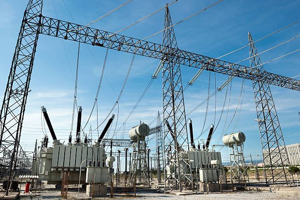
1. What Are the Main Types of Grounding Transformers?
Grounding transformers are primarily classified by winding configuration. The two main types are zigzag and grounded-wye/delta. Their purpose is similar, but their winding arrangements and design considerations differ.
Zigzag Grounding Transformer
A zigzag grounding transformer uses specially interconnected windings on its phases to create an artificial neutral point. Under balanced normal conditions, the magnetic effects largely cancel. During a line-to-ground fault, the transformer provides a path for zero-sequence current.
Zigzag grounding transformers are commonly used in delta-connected distribution networks where a dedicated grounding point is needed. They can provide a compact solution without requiring a separate conventional secondary winding for ordinary loads.
Key considerations include zero-sequence impedance, fault-current duty, winding temperature rise, and compatibility with the neutral grounding resistor or reactor.
Grounded-Wye/Delta Grounding Transformer
This type has a grounded-wye winding connected to the three-phase system and a delta-connected winding. The grounded-wye side provides the neutral point, while the delta winding supports the transformer's behavior under unbalanced and zero-sequence conditions, according to the design.
Grounded-wye/delta grounding transformers may be suitable when the winding arrangement matches the system's grounding and protection requirements. Their ratings and impedance must be verified through engineering calculations and manufacturer data.
2. Zigzag vs. Grounded-Wye/Delta: Key Differences
| Comparison factor | Zigzag grounding transformer | Grounded-wye/delta grounding transformer |
|---|---|---|
| Winding configuration | Interconnected phase windings form a zigzag arrangement | Grounded-wye winding with a delta-connected winding |
| Primary function | Establishes an artificial neutral for grounding | Establishes a neutral using a grounded-wye winding |
| Typical application | Dedicated grounding for delta-connected networks | Grounding applications suited to a grounded-wye/delta arrangement |
| Zero-sequence behavior | Determined by the zigzag winding design and impedance | Determined by winding design, delta connection, and impedance |
| Continuous load supply | Usually not intended for ordinary continuous load supply | Usually designed primarily for grounding duty |
| Main design checks | Neutral current, zero-sequence impedance, short-time thermal duty | Winding ratings, zero-sequence impedance, short-time thermal duty |
| Selection priority | Compact dedicated grounding arrangement | Suitability of the winding configuration for the network |
Neither type is universally better. The correct selection depends on the required fault-current path, system voltage, grounding method, and protection scheme.
3. How Do Grounding Transformers Differ by Grounding Method?
Grounding transformers can also be classified by how their neutral point is connected to earth. This classification is separate from the winding configuration: a zigzag or grounded-wye/delta transformer may be used with an appropriate grounding arrangement.
| Grounding method | How it works | Main advantage | Important limitation |
|---|---|---|---|
| Solid grounding | Neutral is connected directly to earth through a low-impedance path | Provides a strong ground-fault current path | Fault current may be high |
| Resistance grounding | Neutral is connected to earth through a resistor | Limits fault current while supporting detection | Resistor current and time ratings must be coordinated |
| Reactance grounding | Neutral is connected through a reactor | Limits fault current using inductive reactance | Requires careful impedance and system analysis |
| High-resistance grounding | Uses a resistance selected to limit ground-fault current to a low level | Can reduce fault damage and support continued operation in suitable systems | Requires compatible monitoring and protection arrangements |
The grounding method must be selected based on the system's operating philosophy. A design intended to trip immediately on a ground fault may require different settings from one designed to alarm and allow controlled operation while the fault is located.
4. How Does a Neutral Grounding Resistor Affect Transformer Selection?
A neutral grounding resistor (NGR) is often installed between the grounding transformer neutral and earth. Its purpose is to limit ground-fault current to a specified value.
For an initial estimate in a simplified resistive grounding arrangement:
[\RN \approx \frac{V\{LN}}{I_G}]
Where:
- (R_N) is the grounding resistance in ohms.
- (V_{LN}) is the system line-to-neutral voltage in volts.
- (I_G) is the target ground-fault current in amperes.
This estimate does not replace a complete grounding study. Actual current also depends on transformer impedance, network impedance, system capacitance, and fault conditions.
When choosing a grounding transformer and NGR, engineers should verify:
- Rated system voltage and line-to-neutral voltage
- Required ground-fault current
- Fault duration and thermal duty
- Zero-sequence impedance
- Relay sensitivity and clearing time
- Resistor or reactor ratings and environmental conditions
The grounding transformer, grounding impedance, and protective devices should be engineered as one coordinated system.
5. Which Grounding Transformer Type Is Best for Different Applications?
| Application | Common design consideration | Recommended evaluation |
|---|---|---|
| Delta-connected industrial distribution | No accessible neutral point | Compare zigzag and grounded-wye/delta configurations |
| Medium-voltage substation | Defined ground-fault current and relay operation | Confirm zero-sequence impedance and short-time rating |
| Wind farm collector network | Grounding across a distributed three-phase network | Evaluate collector-system capacitance and protection coordination |
| Solar power plant | Compatibility with inverter and collector-system grounding | Review the complete grounding study and equipment requirements |
| Specialized industrial network | Process continuity and fault-response requirements | Select the grounding method before finalizing transformer ratings |
These are starting points, not universal rules. The system study determines whether a grounding transformer is required and which configuration is suitable.
6. What Should Buyers Check Before Ordering?
A professional grounding transformer supplier should be able to confirm the design against the project's technical requirements.
| Required information | Why it matters |
|---|---|
| System voltage and frequency | Establishes electrical and insulation requirements |
| Network connection | Determines the suitable winding configuration |
| Target ground-fault current | Defines the required grounding performance |
| Fault duration | Determines short-time thermal duty |
| Grounding resistor or reactor details | Ensures the complete grounding system is coordinated |
| Applicable standards | Defines design and verification requirements |
| Factory test documentation | Supports quality assurance and commissioning |
Buyers should request the connection diagram, rated data, impedance information, thermal-duty rating, and applicable factory test reports. Where necessary, the supplier should coordinate with the project's electrical engineer to verify compatibility with the protection scheme.
How Does a Grounding Transformer Control Ground-Fault Current and Support Protection?
Ground faults in three-phase power systems can damage insulation, overheat equipment, and create dangerous electrical conditions. If the system has no suitable neutral point, fault current may be difficult for protective relays to detect reliably. Excessive fault current can also increase thermal and mechanical stress, while insufficient fault current may delay protection. A properly designed grounding transformer helps engineers establish a controlled ground-fault current path and coordinate the system's protective devices.
A grounding transformer supports ground-fault protection by providing an artificial neutral point and a path for zero-sequence current. When connected directly to earth or through a neutral grounding resistor (NGR) or reactor, it helps determine ground-fault current according to the system impedance. Protective relays can then detect the fault and initiate an alarm or trip based on their settings. The transformer does not limit current by itself in every configuration; the complete grounding impedance and network design determine the actual fault current.
Understanding this process helps engineers select suitable transformer ratings, grounding impedance, and relay settings. It also helps buyers evaluate whether a grounding transformer will meet the protection requirements of their industrial facility, substation, or renewable energy project.
1. What Happens During a Ground Fault?
A ground fault occurs when an energized phase conductor makes unintended contact with earth or a grounded conductive part. The resulting current depends on the grounding arrangement, the fault impedance, and the electrical characteristics of the network.
In a solidly grounded system, fault current may be high because the return path has low impedance. In an ungrounded system, a single line-to-ground fault may produce relatively low current, often determined largely by the system's phase-to-ground capacitance. However, the healthy phases can experience increased phase-to-ground voltage.
A grounding transformer is useful when the network needs a defined neutral point but does not have one available, such as in certain delta-connected systems.
2. How Does a Grounding Transformer Provide a Fault-Current Path?
The grounding transformer creates an artificial neutral point and provides a path for zero-sequence current during a ground fault.
The process typically follows these steps:
- A phase-to-ground fault occurs. One phase conductor contacts earth or grounded equipment.
- The system becomes unbalanced. The fault changes the phase-current and phase-voltage conditions.
- Zero-sequence current flows. The grounding transformer provides a path through its winding arrangement and the connected grounding network.
- Grounding impedance influences the current. An NGR or reactor, if installed, controls the current according to the selected grounding philosophy.
- Protective devices respond. Relays detect the relevant current or voltage signals and issue an alarm or trip command when their operating criteria are met.
The actual current is determined by the entire zero-sequence circuit, not just the grounding transformer. Transformer impedance, grounding impedance, system capacitance, fault resistance, and fault location can all affect the result.
3. How Is Ground-Fault Current Controlled?
The grounding transformer establishes the neutral point, while the grounding method determines how the neutral connects to earth. The connection may be solid or may include a resistor or reactor.
| Grounding method | Current-control principle | Typical design objective |
|---|---|---|
| Solid grounding | Provides a low-impedance return path | Allow sufficient fault current for fast, dependable protection |
| Resistance grounding | Adds resistance between neutral and earth | Limit current while maintaining reliable fault detection |
| Reactance grounding | Adds inductive reactance to the grounding path | Limit fault current using a reactor |
| Ungrounded operation | Has no intentional neutral-to-earth connection | Fault current may be low, but voltage displacement and fault detection require careful assessment |
Neutral Grounding Resistor Calculation
For an initial estimate in a simplified resistive grounding arrangement, the resistance can be approximated by:
[\RN \approx \frac{V\{LN}}{I_G}]
Where:
- (R_N) = neutral grounding resistance, in ohms
- (V_{LN}) = line-to-neutral voltage, in volts
- (I_G) = target ground-fault current, in amperes
For example, if a system has a line-to-neutral voltage of 6.35 kV and the design target is 200 A, the simplified resistance estimate is:
[\R_N \approx \frac{6350}{200}=31.75\ \Omega]
This is an illustrative calculation, not a final equipment specification. Actual design must account for the complete network impedance, fault conditions, and the required resistor time rating.
4. How Does a Grounding Transformer Support Protective Relays?
Protective relays need suitable electrical signals to distinguish a ground fault from normal operating conditions. A grounding transformer can help create a predictable zero-sequence current path, allowing the protection system to detect earth faults more reliably.
Depending on the network design, protection may use:
- Residual or zero-sequence current: Detects current imbalance associated with a ground fault.
- Neutral current: Measures current flowing through the grounding connection.
- Residual or neutral voltage: Detects neutral displacement during a ground fault.
- Directional ground-fault protection: Uses current and voltage information to identify the fault direction in networks where this is required.
The relay type, current transformer ratios, voltage transformer connections, pickup thresholds, and time delays must be coordinated with the grounding arrangement.
A grounding transformer alone does not guarantee that a relay will trip. Correct relay settings, suitable sensing equipment, and verified trip logic are also necessary.
5. What Is the Relationship Between the Grounding Transformer and the NGR?
The grounding transformer and neutral grounding resistor perform different but complementary functions.
| Component | Primary function | Key selection parameter |
|---|---|---|
| Grounding transformer | Establishes a neutral point and provides a zero-sequence path | Voltage, impedance, and short-time current rating |
| Neutral grounding resistor | Limits resistive ground-fault current | Resistance, current rating, and fault duration |
| Protective relay | Detects the fault and initiates the required response | Pickup setting, timing, and protection logic |
| Current transformer | Supplies a current signal to the protection system | Ratio, accuracy, and suitable fault-current performance |
| Grounding conductor and earth connection | Provides the designed electrical connection to earth | Conductor capacity, connection integrity, and applicable requirements |
The grounding transformer must withstand the current associated with the specified fault duration. The NGR must also be rated for the required current and time. Both ratings should match the system study and relay-clearing time.
A grounding transformer alone guarantees that every ground fault will be detected and cleared.False
The transformer provides a grounding point and fault-current path, but reliable detection and clearing also depend on grounding impedance, sensing equipment, relay settings, trip logic, and the complete protection design.
6. What Should Engineers Verify During Design and Commissioning?
A coordinated grounding and protection design should be checked before energization.
Important checks include:
- Confirming the system voltage, frequency, winding configuration, and grounding philosophy.
- Verifying zero-sequence impedance and calculating expected ground-fault current.
- Checking grounding resistor or reactor ratings and time duty.
- Confirming current and voltage transformer connections and ratios.
- Reviewing relay pickup values, time delays, and trip logic.
- Verifying neutral connections, grounding conductors, terminal identification, and enclosure grounding.
- Reviewing factory test reports and completing the specified commissioning tests.
Testing should follow the approved commissioning procedure and applicable standards. Ground-fault testing must be performed by qualified personnel using appropriate methods and equipment.
What Technical Specifications Should Buyers Consider When Selecting a Grounding Transformer?
Selecting a grounding transformer based only on system voltage or purchase price can create costly problems. An incorrectly rated unit may fail to provide the required ground-fault current, overheat during a fault, or prevent protective relays from operating as intended. For industrial facilities, substations, and renewable energy projects, buyers need to evaluate electrical ratings, winding configuration, grounding impedance, short-time duty, insulation, and testing requirements before placing an order.
When selecting a grounding transformer, buyers should verify the system voltage and frequency, winding configuration, zero-sequence impedance, required ground-fault current, fault duration, neutral grounding resistor or reactor ratings, insulation level, thermal duty, installation conditions, applicable standards, and factory test documentation. These specifications must be coordinated with the power-system grounding study and protection scheme to ensure safe, reliable operation.
A clear technical specification helps buyers compare suppliers on engineering suitability rather than price alone. The following checklist explains the key parameters and how they affect grounding transformer selection.
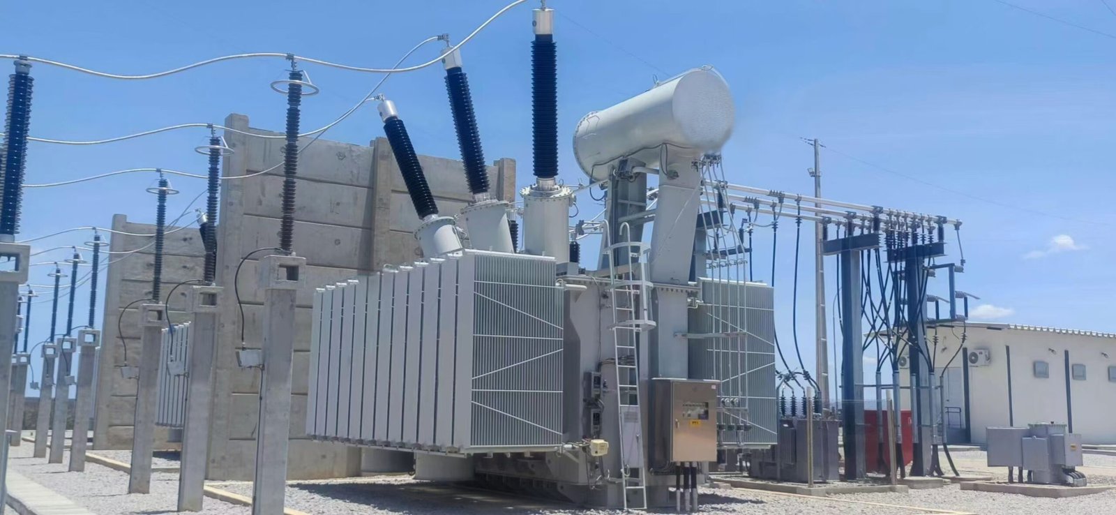
1. Electrical Ratings and System Compatibility
The first step is to confirm that the grounding transformer matches the electrical network.
| Specification | What buyers should confirm | Why it matters |
|---|---|---|
| Rated system voltage | Nominal line-to-line voltage | Determines the required electrical design and insulation coordination |
| Rated frequency | 50 Hz or 60 Hz, as applicable | Ensures compatibility with the network |
| Phase configuration | Three-phase system and connection arrangement | Establishes the appropriate grounding transformer design |
| Rated current or duty | Required neutral current and specified duration | Ensures the transformer can withstand the intended fault duty |
| Winding configuration | Zigzag or grounded-wye/delta | Determines how the neutral point and zero-sequence path are established |
| Terminal arrangement | Phase terminals, neutral terminal, and earth connection | Supports correct installation and system integration |
Buyers should provide the actual system configuration rather than asking for a generic three-phase transformer. A grounding transformer is a specialized component whose ratings must reflect the grounding function it will perform.
2. Winding Configuration: Zigzag or Grounded-Wye/Delta
The two common grounding transformer configurations are zigzag and grounded-wye/delta.
Zigzag Grounding Transformer
A zigzag grounding transformer uses interconnected phase windings to establish an artificial neutral point. It is commonly used when a delta-connected system needs a grounding reference without requiring a conventional secondary winding for ordinary loads.
Grounded-Wye/Delta Grounding Transformer
This design uses a grounded-wye winding connected to the system and a delta-connected winding. Its suitability depends on the required grounding characteristics, winding ratings, and zero-sequence behavior.
| Selection factor | Zigzag | Grounded-wye/delta |
|---|---|---|
| Main purpose | Dedicated neutral grounding | Neutral grounding through a grounded-wye winding |
| Key design concern | Zero-sequence impedance and thermal duty | Winding ratings and zero-sequence characteristics |
| Buyer action | Request connection and impedance data | Request connection and impedance data |
Neither configuration is automatically better. The choice should follow the grounding study and the manufacturer's verified design data.
3. Zero-Sequence Impedance and Ground-Fault Current
Zero-sequence impedance is one of the most important technical specifications because it affects ground-fault current.
During a line-to-ground fault, the grounding transformer provides a path for zero-sequence current. The resulting current depends on the transformer's impedance, any grounding resistor or reactor, system capacitance, fault impedance, and the overall network configuration.
For a simplified resistive grounding arrangement, an initial estimate of neutral grounding resistance is:
[\RN \approx \frac{V\{LN}}{I_G}]
Where:
- (R_N) = neutral grounding resistance in ohms
- (V_{LN}) = line-to-neutral voltage in volts
- (I_G) = target ground-fault current in amperes
This equation is only a preliminary estimate. The final design should use the complete zero-sequence network and verify that the grounding transformer and associated equipment can withstand the specified fault current.
Buyer tip: Request the manufacturer's zero-sequence impedance data and confirm that the proposed grounding arrangement achieves the required fault-current target.
4. Short-Time Current Rating and Thermal Duty
Grounding transformers are often designed for short-time grounding duty rather than continuous full-load service. Buyers should specify both the expected ground-fault current and the time the transformer must withstand it.
For example, a requirement such as “200 A for 10 seconds” is more meaningful than a current value without a duration. The actual current and time must be determined from the system grounding and protection study.
| Parameter | Information to specify |
|---|---|
| Ground-fault current | Required amperes |
| Fault duration | Required seconds |
| Duty cycle | Any repeated-fault or operating requirements |
| Thermal withstand | Manufacturer-confirmed capability for the specified duty |
| Protection clearing time | Expected relay and breaker operating time |
Do not assume that two grounding transformers with the same voltage rating can withstand the same fault duty. Their winding design, impedance, and thermal capabilities may differ.
5. Neutral Grounding Resistor or Reactor Requirements
Some grounding transformers are supplied with a separate neutral grounding resistor (NGR) or reactor. Buyers should define whether this equipment is included in the supply scope or purchased separately.
For an NGR, verify:
- Resistance value in ohms
- Rated neutral current
- Current duration or time rating
- Insulation and voltage rating
- Enclosure protection and environmental suitability
- Monitoring and alarm requirements, where applicable
For a grounding reactor, verify the required reactance, current rating, thermal duty, and coordination with the network.
The grounding transformer and impedance device should be specified as a coordinated package. Otherwise, a mismatch between their ratings can undermine the intended protection scheme.
6. Insulation Level, Cooling, and Installation Conditions
Insulation and environmental specifications affect reliability throughout the equipment's service life.
| Specification | What to review |
|---|---|
| Insulation level | Rated withstand requirements and coordination with system voltage |
| Insulation medium | Dry-type or liquid-immersed design, as appropriate |
| Cooling method | Manufacturer's proposed cooling arrangement and thermal capability |
| Ambient temperature | Expected site temperature range |
| Altitude | Whether installation altitude affects cooling or insulation requirements |
| Enclosure and protection | Indoor/outdoor use, ingress protection, and corrosion exposure |
| Installation space | Clearances, access for maintenance, and cable termination requirements |
The appropriate insulation and cooling design depends on the application, site conditions, and applicable standards. Buyers should not assume that all grounding transformers use the same insulation medium or enclosure design.
7. Applicable Standards and Factory Testing
A grounding transformer should be supplied with documentation that allows the buyer to verify the design and confirm the equipment meets the purchase specification.
Depending on the project and applicable requirements, buyers may request:
- Approved technical drawings and connection diagrams
- Nameplate data and winding configuration
- Winding resistance and turns-ratio test results, where applicable
- Insulation test reports
- Impedance data relevant to the grounding design
- Routine factory test reports
- Applicable design and testing standards
- Installation, operation, and maintenance instructions
The applicable standard depends on the equipment type, voltage class, market, and project specification. Buyers should confirm the required IEC, IEEE, or local requirements with the project engineer rather than relying on a general statement that the transformer is “international standard compliant.”
8. Supplier Evaluation and Total Project Cost
The lowest initial price may not represent the lowest project cost. Buyers should compare technical compliance, manufacturing quality, delivery schedule, documentation, and long-term support.
| Evaluation factor | Questions to ask the supplier |
|---|---|
| Engineering capability | Can the supplier review the grounding study and confirm the proposed design? |
| Manufacturing quality | Are quality-control procedures and traceable test records available? |
| Technical documentation | Are drawings, ratings, impedance data, and test reports included? |
| Customization | Can the design meet the specified voltage, fault current, and duration? |
| Delivery and logistics | Are lead time, packaging, and transport requirements confirmed? |
| After-sales support | Are installation guidance and technical assistance available? |
A reliable supplier should identify any missing design information before finalizing the quotation. This reduces the risk of ordering equipment that cannot meet the system's actual grounding requirements.
Grounding Transformer Selection Checklist
Before issuing a purchase order, confirm the following:
- System voltage and frequency
- Three-phase network configuration
- Zigzag or grounded-wye/delta winding arrangement
- Required zero-sequence impedance
- Target ground-fault current and duration
- NGR or reactor requirements
- Insulation, cooling, and site conditions
- Applicable standards and factory testing
- Approved drawings and terminal connections
- Delivery, documentation, and warranty terms
How Can Buyers Choose a Reliable Grounding Transformer for Their Electrical System?
Choosing an unsuitable grounding transformer can lead to poor ground-fault detection, excessive electrical stress, unexpected equipment downtime, and expensive replacement work. Buyers may be tempted to compare suppliers mainly by price or rated voltage, but these factors alone cannot confirm whether a grounding transformer will perform safely in a specific electrical network. A reliable selection process must consider the system configuration, grounding requirements, fault-current duty, manufacturing quality, and supplier support.
To choose a reliable grounding transformer, buyers should first confirm the system voltage, frequency, and three-phase connection, then verify the required winding configuration, zero-sequence impedance, ground-fault current, short-time thermal rating, and grounding resistor or reactor requirements. They should also evaluate applicable standards, factory test reports, manufacturing quality, delivery capability, warranty, and technical support. The final design must match the electrical system's grounding study and protection scheme.
A systematic evaluation helps buyers reduce technical risks and compare suppliers fairly. The following guide explains what to check before requesting a quotation, approving a design, or placing an order.
1. Confirm Your Electrical System Requirements First
Before contacting suppliers, collect the essential information about your electrical network. A grounding transformer must be designed for the system's grounding function rather than selected as a generic transformer.
Important details include:
- Nominal line-to-line voltage and system frequency
- Three-phase connection, such as a delta-connected network
- Whether an accessible neutral point already exists
- Required ground-fault current and fault duration
- Grounding method and protection philosophy
- Indoor or outdoor installation conditions
- Applicable project and local electrical requirements
This information helps the supplier determine whether a grounding transformer is required and which configuration is appropriate.
2. Choose the Correct Grounding Transformer Type
The two most common configurations are zigzag and grounded-wye/delta. Both can establish an artificial neutral point, but their winding arrangements and electrical characteristics differ.
| Selection factor | Zigzag grounding transformer | Grounded-wye/delta grounding transformer |
|---|---|---|
| Winding arrangement | Interconnected zigzag windings | Grounded-wye winding with a delta-connected winding |
| Main function | Provides a neutral point and zero-sequence current path | Provides a neutral point through a grounded-wye winding |
| Typical application | Dedicated grounding of suitable delta-connected systems | Grounding systems where the winding arrangement matches the network requirements |
| Key design check | Zero-sequence impedance and thermal duty | Winding ratings, zero-sequence impedance, and thermal duty |
Neither type is universally superior. The choice should follow the system study and the manufacturer's verified technical data.
3. Verify Zero-Sequence Impedance and Fault-Current Rating
Zero-sequence impedance is a critical parameter because it affects the ground-fault current available to the protection system.
The grounding transformer provides a path for zero-sequence current, but the actual current also depends on the grounding resistor or reactor, network impedance, system capacitance, fault resistance, and fault location.
For a simplified resistive grounding arrangement, the preliminary resistance estimate is:
[\RN \approx \frac{V\{LN}}{I_G}]
Where (RN) is neutral grounding resistance, (V\{LN}) is line-to-neutral voltage, and (I_G) is the target ground-fault current.
This equation is only an initial estimate. Final values must be established through a grounding and protection study.
Buyers should ask suppliers to confirm:
- Zero-sequence impedance and relevant test data
- Rated ground-fault current
- Required fault duration
- Short-time thermal capability
- Compatibility with the proposed neutral grounding resistor or reactor
A supplier that cannot provide the relevant impedance and duty information may not be able to demonstrate that its proposed unit meets the project's grounding requirements.
4. Evaluate Manufacturing Quality and Factory Testing
A reliable grounding transformer should be supported by documented quality-control procedures and test results. Buyers should verify that the supplied equipment matches the approved technical specification and drawings.
| Quality item | What buyers should request |
|---|---|
| Technical drawings | Winding configuration, terminal arrangement, dimensions, and connection diagram |
| Nameplate information | Rated voltage, frequency, ratings, and identification data |
| Routine factory tests | Test reports required by the applicable standard and purchase specification |
| Impedance information | Zero-sequence or other relevant design data |
| Quality documentation | Applicable quality-management and inspection records |
| Traceability | Equipment serial number and corresponding test documentation |
Applicable standards depend on the equipment design, voltage class, market, and project specification. Buyers should identify the required IEC, IEEE, or local standards with their engineering team and verify the supplier's claimed compliance.
5. Check Insulation, Cooling, and Site Suitability
Even a correctly rated grounding transformer can perform poorly if its insulation, cooling, or enclosure is unsuitable for the installation environment.
Consider the following:
- Insulation level: Confirm that the equipment meets the system's insulation coordination requirements.
- Cooling design: Verify the cooling arrangement and thermal capability for the specified duty.
- Ambient temperature: Check the expected site temperature range.
- Altitude: Confirm whether installation altitude affects cooling or insulation requirements.
- Enclosure protection: Evaluate moisture, dust, corrosion, and outdoor exposure.
- Maintenance access: Ensure sufficient clearance for inspection, cable termination, and replacement work.
The supplier should identify any installation limitations that could affect rated performance.
6. Compare Supplier Experience and Technical Support
A reliable supplier does more than manufacture the equipment. It should be able to understand the application, identify missing information, and explain how the proposed grounding transformer meets the design requirements.
Ask potential suppliers:
- Can you review our system configuration and grounding requirements?
- Can you provide verified zero-sequence impedance and short-time duty data?
- Can you supply the required factory test reports?
- Can the transformer be customized to meet our electrical and installation requirements?
- What technical assistance, warranty, and after-sales service are available?
Prioritize suppliers that provide clear, consistent answers and complete documentation rather than relying solely on marketing claims.
7. Compare Total Project Cost, Not Just Purchase Price
The lowest quotation may not deliver the best long-term value. Buyers should compare the complete supply scope, technical compliance, delivery schedule, documentation, warranty, and maintenance requirements.
| Cost factor | Why it matters |
|---|---|
| Initial equipment price | Establishes the basic purchase cost |
| Grounding resistor or reactor | May be supplied separately or as part of a package |
| Engineering and testing | Can affect commissioning time and project cost |
| Installation requirements | May influence civil work, cable connections, and site preparation |
| Delivery schedule | Delays can affect project completion |
| Warranty and service | Influence long-term maintenance and support costs |
Ensure that competing quotations use the same electrical ratings, fault duration, grounding configuration, testing requirements, and scope of supply. Otherwise, a lower price may simply reflect a different or incomplete specification.
8. Use a Final Buyer Checklist
Before approving the purchase, confirm that the supplier's proposal addresses all essential requirements.
- System voltage and frequency are correct.
- The proposed winding configuration suits the network.
- Zero-sequence impedance is documented and verified.
- Ground-fault current and fault duration are specified.
- Thermal and short-time ratings meet the design requirements.
- The NGR or reactor requirements are clearly defined.
- Insulation, cooling, and enclosure protection suit the site.
- Applicable standards and factory tests are documented.
- Technical drawings and terminal details are approved.
- Warranty, delivery, and after-sales support are agreed.
Conclusion
A grounding transformer provides a neutral grounding point when a three-phase power system does not have a suitable one. By establishing a defined path for ground-fault current, it supports voltage stability, insulation protection, and reliable ground-fault detection. The most suitable design depends on the system voltage, grounding method, fault-current requirements, duration of faults, and protection settings. Proper engineering coordination is essential to ensure the grounding transformer works effectively with the overall electrical system.
FAQ
Q1: What is a grounding transformer?
A grounding transformer creates a neutral point in a power system without one, providing a path for ground-fault current and supporting electrical protection.
Q2: Why is a grounding transformer needed?
It helps detect ground faults, control fault current, stabilize phase-to-ground voltages, and improve power system safety.
Q3: What are the main types of grounding transformers?
The two common types are zigzag and wye-delta grounding transformers. Selection depends on system configuration, fault-current requirements, and protection design.
Q4: How do you select a grounding transformer?
Consider system voltage, frequency, grounding method, required fault current, fault duration, insulation level, and compatibility with protective devices.
Q5: How is a grounding transformer maintained?
Perform regular visual inspections, check connections and insulation, test grounding equipment and protective relays, and follow manufacturer maintenance guidelines.
References
- IEC 60076-1 — Power Transformers: General
https://webstore.iec.ch/en/publication/588 - IEC 60076-2 — Power Transformers: Temperature Rise for Liquid-Immersed Transformers
https://webstore.iec.ch/en/publication/604 - IEC 60076-3 — Power Transformers: Insulation Levels, Dielectric Tests and External Clearances in Air
https://webstore.iec.ch/en/publication/605 - IEC 60076-5 — Power Transformers: Ability to Withstand Short Circuit
https://webstore.iec.ch/en/publication/607 - IEEE C57.12.00 — General Requirements for Liquid-Immersed Distribution, Power, and Regulating Transformers
https://standards.ieee.org/ieee/C57.12.00/6962/ - IEEE C57.12.90 — Test Code for Liquid-Immersed Distribution, Power, and Regulating Transformers
https://standards.ieee.org/ieee/C57.12.90/ - IEEE C57.12.80 — Terminology for Power and Distribution Transformers
https://standards.ieee.org/ieee/C57.12.80/7006/ - IEEE Technology Navigator — Power Transformers
https://technav.ieee.org/topic/power-transformers/ - U.S. Department of Energy — Electricity Delivery and Grid Systems
https://www.energy.gov/oe - IEEE C57.116 — Transformers Directly Connected to Generators
https://standards.ieee.org/ieee/C57.116/