
Choosing between a power transformer and a distribution transformer can be challenging because both are essential for transferring electrical energy and changing voltage levels. However, selecting the wrong type can result in inefficient operation, unnecessary investment, higher energy losses, or equipment that does not meet the requirements of the electrical network. Understanding their differences helps engineers, utility companies, and project buyers make the right equipment decision.
The main difference between a power transformer and a distribution transformer is their application and operating role in the electrical power system. A power transformer is primarily used in generation stations and transmission networks to transfer large amounts of electrical power at high voltage, generally operating close to its rated load. A distribution transformer reduces medium voltage to low voltage for delivery to end users and is designed to operate efficiently under varying loads throughout the day. They also differ in capacity, voltage rating, load characteristics, efficiency requirements, and typical installation locations.
Although both transformer types operate through electromagnetic induction, their design priorities and operating conditions are different. The following guide compares their functions, technical characteristics, applications, and selection criteria to help you identify the most suitable transformer for your project.
What Is the Difference Between a Power Transformer and a Distribution Transformer in Their Basic Functions?
Choosing between a power transformer and a distribution transformer can be confusing because both devices transfer electrical energy between voltage levels through electromagnetic induction. However, selecting the wrong type for an application can lead to unsuitable capacity, inefficient operation, unnecessary investment, or difficulties meeting the requirements of a power network. Understanding their basic functions, operating conditions, and typical installation locations helps engineers and buyers identify the right equipment before specifying or purchasing a transformer.
The basic difference is that a power transformer is primarily used to transfer large amounts of electrical power between high-voltage transmission or sub-transmission networks, while a distribution transformer reduces medium-voltage electricity to lower utilization voltages for delivery to homes, commercial buildings, and industrial loads. Power transformers commonly operate near high loading levels in transmission networks, whereas distribution transformers are designed to supply changing loads efficiently throughout the day.
Although their functions differ, both transformer types are essential to a reliable electrical supply system. This article explains how they work within the power network, compares their main characteristics, and outlines the practical factors to consider when selecting either type.
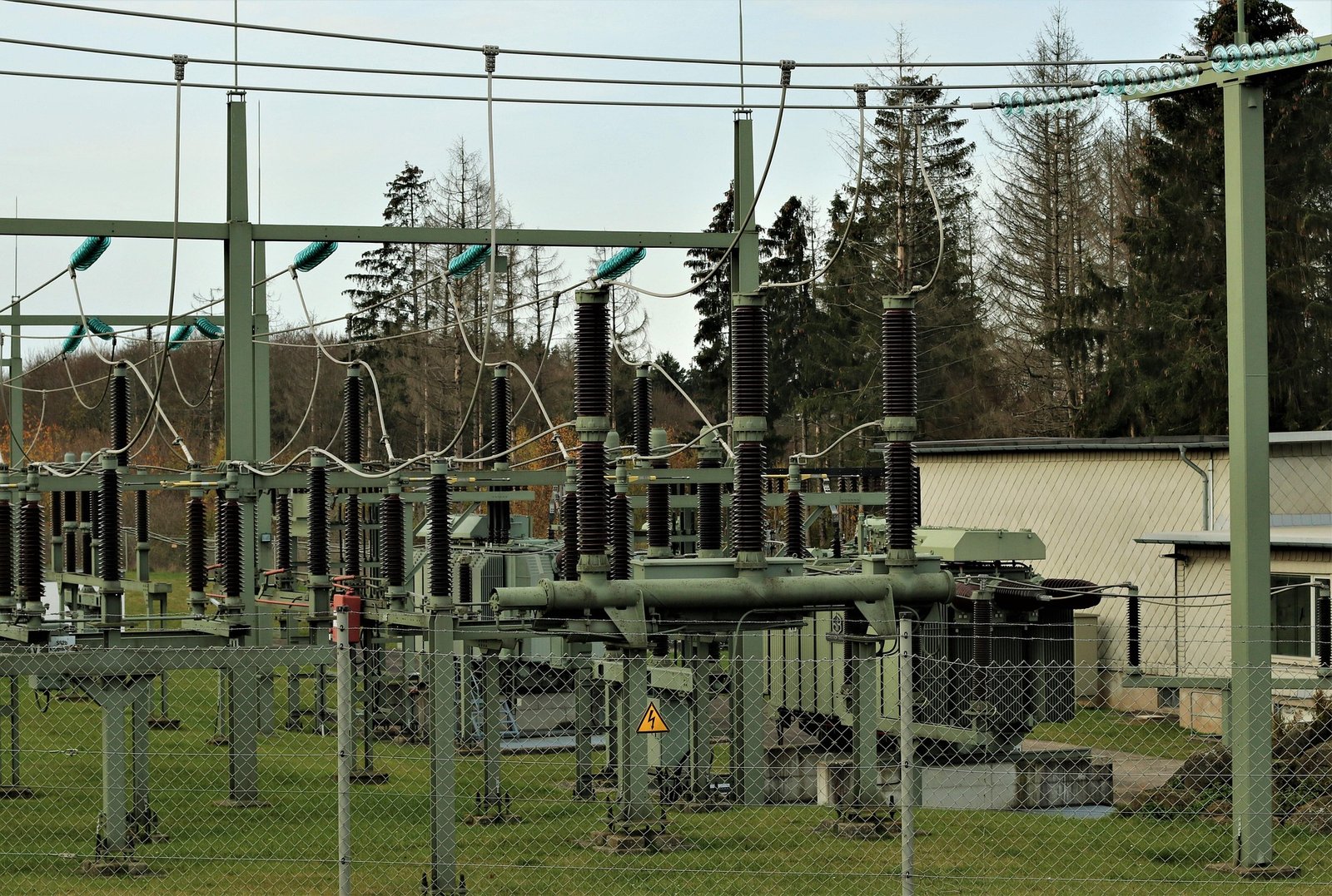
1. What Is a Power Transformer?
A power transformer is a high-capacity electrical transformer used primarily in generation, transmission, and sub-transmission systems. Its basic function is to transfer electrical power between network voltage levels so electricity can be transmitted or distributed efficiently.
At a power station, a generator produces electricity at a voltage determined by the generator's design. A step-up power transformer raises this voltage before electricity enters the transmission network. Increasing voltage allows the same amount of apparent power to be transmitted at a lower current, helping reduce resistive losses in transmission conductors.
At a transmission or grid substation, a power transformer may also reduce voltage from one high-voltage level to another lower transmission or sub-transmission level. Its function therefore depends on its position in the network and the direction of power flow.
Power transformers are generally designed for large MVA ratings, high insulation requirements, and demanding operating conditions. Many are oil-immersed designs with radiators, cooling equipment, bushings, monitoring devices, and protective accessories, although construction varies by application and manufacturer.
2. What Is a Distribution Transformer?
A distribution transformer is designed to reduce medium-voltage electricity to the lower voltage required by end users. Its basic function is to provide the final voltage transformation between a distribution network and the electrical loads connected to it.
For example, electricity may reach a neighborhood through a medium-voltage feeder. A distribution transformer reduces that voltage to the utilization voltage required by nearby homes, shops, offices, or other facilities. The exact primary and secondary voltage ratings depend on the local electrical network and project requirements.
Distribution transformers are commonly installed close to consumers to limit the length of low-voltage distribution circuits. They may be pole-mounted, pad-mounted, or installed indoors in suitable electrical rooms.
Unlike power transformers, distribution transformers often experience significant load variation. Demand may be low overnight and rise during business hours or residential peak periods. Their design therefore places particular emphasis on efficient operation under changing and sometimes relatively light loading conditions.
A distribution transformer is primarily used to reduce distribution-network voltage to the utilization voltage required by end users.True
Distribution transformers provide the final voltage transformation between medium-voltage distribution feeders and low-voltage consumer supply systems.
3. How Do Their Basic Functions Differ?
The clearest distinction is their position and purpose within the electrical power system.
A power transformer supports the transfer of large quantities of electricity between generation, transmission, and sub-transmission voltage levels. A distribution transformer supplies electricity at a voltage suitable for direct use by customers.
Consider a simplified power network:
- A generator produces electrical power.
- A step-up power transformer raises the generator voltage.
- Transmission lines carry electricity over long distances.
- A substation transformer reduces voltage to a distribution-network level.
- A distribution transformer reduces the voltage again for local consumers.
This arrangement illustrates why the two transformer types are complementary rather than interchangeable. Power transformers handle bulk power transfer, while distribution transformers provide the final voltage conversion needed for utilization.
4. Power Transformer vs. Distribution Transformer: Key Differences
| Comparison factor | Power transformer | Distribution transformer |
|---|---|---|
| Basic function | Transfers large power between generation, transmission, and sub-transmission voltage levels | Supplies electricity at utilization voltage to end users |
| Typical network position | Power stations and transmission or sub-transmission substations | Local distribution networks, near consumers |
| Voltage application | Commonly high-voltage and extra-high-voltage systems, depending on the network | Commonly medium-voltage primary and low-voltage secondary systems |
| Capacity | Generally large MVA ratings | Generally smaller kVA or MVA ratings |
| Load characteristics | Often designed for high loading and bulk power transfer | Designed for variable customer demand, including periods of light loading |
| Efficiency priorities | Low losses and reliable operation at expected high loading | Strong efficiency across a changing daily load profile |
| Common installations | Generating stations, grid substations, transmission facilities | Pole-mounted, pad-mounted, indoor, and local network installations |
| Typical customers or users | Utilities, generators, transmission operators, large industrial facilities | Utilities, commercial buildings, residential networks, and smaller industrial users |
These are general industry distinctions, not universal rating boundaries. Voltage, capacity, construction, and terminology vary by country, utility practice, and manufacturer. The actual application and specified operating duty should determine the transformer category.
5. How Do Power Transformers Support Transmission Networks?
Power transformers make large-scale electricity transmission practical. When electricity is transmitted at a higher voltage, the current required to deliver a given apparent power is reduced, assuming the power factor and system conditions remain comparable.
For a balanced three-phase system, apparent power is calculated as:
[\S=\sqrt{3}V_{LL}I_L]
Where:
- (S) is apparent power in volt-amperes
- (V_{LL}) is line-to-line voltage
- (I_L) is line current
For a given apparent power, increasing the transmission voltage reduces the current. Since conductor losses are proportional to the square of current, this can substantially reduce transmission losses.
Power transformers also help utilities manage different network voltage levels. A grid may contain several transmission and sub-transmission voltages, each serving a particular operational purpose. Transformers connect these levels while providing the required electrical insulation and voltage transformation.
Their specifications must account for rated MVA, voltage ratio, impedance, insulation level, cooling method, short-circuit withstand capability, protection, and site conditions.
6. How Do Distribution Transformers Supply End Users?
Distribution transformers perform the final voltage conversion before electricity reaches customer equipment. They help ensure that the voltage supplied to local loads is compatible with the electrical system used in homes, commercial buildings, and industrial facilities.
For example, a utility may distribute electricity through a medium-voltage feeder and use a local distribution transformer to supply a low-voltage network. The transformer may serve one building, several buildings, or a group of customers, depending on its capacity and installation arrangement.
Because customer demand changes throughout the day, distribution transformer selection must consider more than the connected load's nominal power. Engineers should evaluate:
- Peak demand and expected load growth
- Daily and seasonal load profiles
- Power factor and load balance
- Ambient temperature and installation conditions
- Voltage regulation requirements
- Transformer losses and energy efficiency
- Protection and fault-current requirements
A distribution transformer that is too small may experience excessive loading and temperature rise. An unnecessarily oversized unit may increase initial investment and may not deliver the most economical performance under the actual load profile.
7. How Do Their Losses and Cooling Requirements Compare?
Both power and distribution transformers experience core losses and winding losses. Core losses occur whenever the transformer is energized, while winding losses increase with current and therefore vary with loading.
For power transformers, engineers commonly pay close attention to losses under the expected operating load because these units may carry substantial power for long periods. Distribution transformers require particular attention to the balance between no-load losses and load losses because they can remain energized even when customer demand is relatively low.
Cooling arrangements depend on capacity, design, installation environment, and required temperature-rise performance. Oil-immersed units may use natural or forced oil and air circulation, while dry-type transformers commonly rely on natural or forced air cooling.
| Design consideration | Power transformer | Distribution transformer |
|---|---|---|
| Core loss | Important because the unit may remain energized continuously | Particularly important because the transformer may be lightly loaded for extended periods |
| Load loss | Significant at high operating currents | Must be evaluated against variable customer demand |
| Cooling design | May require substantial radiators, fans, pumps, or other engineered cooling arrangements | Often uses simpler cooling arrangements, depending on rating and site conditions |
| Thermal assessment | Based on rated loading, overload duty, ambient conditions, and cooling stages | Based on daily load cycles, peak demand, ambient conditions, and thermal recovery |
| Maintenance | Often includes detailed monitoring and maintenance of cooling, insulation, and protective systems | Depends on design and installation; may include oil testing, connection inspection, and temperature checks |
Cooling designations and applicable requirements should be confirmed against the manufacturer's documentation and the relevant standards. A cooling method should not be assumed to increase a transformer's rated capacity unless the manufacturer has designed and rated the equipment for that operating stage.
8. Which Transformer Should You Select for Your Application?
The correct choice depends on the transformer's function within the electrical system rather than simply its physical size or rated capacity.
Choose a power transformer when the application involves:
- Connecting a generating station to a transmission network
- Transforming voltage between transmission or sub-transmission levels
- Handling large quantities of electrical power at a grid substation
- Supplying a large industrial or utility network through high-capacity transformation
Choose a distribution transformer when the application involves:
- Reducing medium-voltage feeder voltage to low-voltage utilization levels
- Supplying residential neighborhoods
- Providing electricity to commercial buildings
- Serving local industrial facilities and distribution loads
Before purchasing, confirm the primary and secondary voltages, phase configuration, rated capacity, frequency, vector group, impedance, insulation level, cooling arrangement, installation environment, efficiency requirements, and protection provisions.
For a utility or industrial project, engineers should also evaluate applicable IEC 60076 or IEEE C57 requirements, together with local electrical codes and project specifications. The precise standard and edition depend on the project location and equipment type.
How Do Power Transformers and Distribution Transformers Differ in Voltage Ratings and Capacity?
Choosing between a power transformer and a distribution transformer requires more than comparing their physical size or general purpose. If the voltage rating is unsuitable, the transformer may not connect correctly to the electrical network; if its capacity is poorly matched to the load, it may operate inefficiently, experience excessive temperature rise, or fail to accommodate future demand. Understanding the differences in voltage ratings and capacity helps engineers, utilities, contractors, and equipment buyers specify the correct transformer for each stage of a power system.
Power transformers generally have higher voltage ratings and larger MVA capacities because they transfer bulk electrical power between generation, transmission, and sub-transmission networks. Distribution transformers typically have medium-voltage primary ratings, low-voltage secondary ratings, and smaller kVA or MVA capacities because they supply local loads such as homes, commercial buildings, and industrial facilities. However, the distinction is based on application and operating duty—not on one universal voltage or capacity threshold.
Both transformer types use electromagnetic induction to transfer electrical energy between windings, but their voltage ranges and capacity requirements reflect different network responsibilities. This article explains the typical rating differences, how capacity is calculated, and what buyers should verify before selecting either type.
1. How Do Power Transformer Voltage Ratings Differ?
Power transformers are commonly used at generating stations and transmission or sub-transmission substations. Their voltage ratings are selected to match the voltage levels of the connected power network.
At a generating station, a step-up power transformer raises the generator's output voltage to a higher transmission voltage. This allows electricity to travel over long distances at a lower current for a given power level, reducing conductor losses. At substations, other power transformers may reduce voltage from one transmission level to another or supply a sub-transmission network.
Depending on the power system, power transformers may operate at voltage levels ranging from tens of kilovolts to hundreds of kilovolts. Some large grid applications use extra-high-voltage ratings. These values are examples of common system classes, not universal limits defining a power transformer.
The transformer's rated voltage must correspond to the system's maximum operating voltage, insulation coordination requirements, grounding arrangement, and applicable standards. Engineers also need to distinguish between winding rated voltage, nominal system voltage, and the highest voltage for equipment.
2. How Do Distribution Transformer Voltage Ratings Differ?
Distribution transformers are generally installed closer to end users. Their primary winding connects to a medium-voltage distribution feeder, while their secondary winding supplies the lower voltage required by local consumers.
Common distribution primary voltage levels vary by region and utility. Examples include 4.16 kV, 11 kV, 13.8 kV, 22 kV, and 33 kV. Secondary voltages also vary according to local supply systems. Examples include 120/240 V single-phase service and 208Y/120 V or 480Y/277 V three-phase service in North American applications.
These examples should not be treated as interchangeable standard combinations. The correct primary and secondary ratings depend on the utility network, phase configuration, grounding method, and customer load requirements.
Distribution transformers are designed to maintain suitable voltage at the point of use under changing load conditions. Their voltage regulation, tap arrangements, and impedance therefore need to be considered alongside their nominal voltage ratio.
3. Typical Voltage Rating Comparison
| Comparison factor | Power transformer | Distribution transformer |
|---|---|---|
| Primary voltage | Commonly high-voltage or extra-high-voltage network levels, depending on application | Commonly medium-voltage distribution feeder levels |
| Secondary voltage | Another transmission, sub-transmission, or large industrial voltage level | Usually low-voltage utilization or local distribution level |
| Typical role | Step up generator voltage or transform between grid voltage levels | Reduce distribution voltage for customer supply |
| Installation location | Generating stations and transmission or sub-transmission substations | Pole-mounted, pad-mounted, or indoor local distribution sites |
| Voltage range | Can extend from tens to hundreds of kilovolts | Commonly several kilovolts to tens of kilovolts on the primary side, with low-voltage secondary output |
| Main selection concern | Network voltage compatibility, insulation level, system stability, and bulk power transfer | Feeder compatibility, customer utilization voltage, voltage regulation, and local load requirements |
The table shows the general difference in application. Actual voltage ratings depend on the electrical system and should be confirmed against the project specification and manufacturer documentation.
4. How Do Power Transformer and Distribution Transformer Capacities Differ?
Transformer capacity is normally expressed in kilovolt-amperes (kVA) or megavolt-amperes (MVA), rather than kilowatts (kW). This is because a transformer must accommodate voltage and current, while the real power delivered to a load also depends on power factor.
Power transformers are commonly designed for large MVA ratings because they transfer bulk power across generation and transmission networks. Their capacities may range from several MVA to hundreds of MVA, depending on the station, network duty, and transformer design.
Distribution transformers generally have smaller ratings because they serve local groups of consumers or individual facilities. Common examples include 25 kVA, 50 kVA, 100 kVA, 250 kVA, 500 kVA, and 1,000 kVA. Larger distribution installations may use ratings in the MVA range.
These figures are illustrative rather than strict classification boundaries. A large distribution transformer can have a higher rating than a smaller power transformer. The application, network position, loading duty, and utility terminology determine how the equipment is classified.
5. Typical Capacity Comparison
| Capacity consideration | Power transformer | Distribution transformer |
|---|---|---|
| Common rating scale | Usually specified in MVA for bulk power applications | Often specified in kVA; larger units may be rated in MVA |
| Typical examples | 10 MVA, 40 MVA, 100 MVA, 250 MVA | 25 kVA, 100 kVA, 250 kVA, 500 kVA, 1,000 kVA |
| Load served | Generators, transmission networks, substations, and large industrial systems | Residential areas, commercial buildings, and local industrial loads |
| Load pattern | Often carries substantial power for extended periods, depending on network duty | Frequently experiences daily and seasonal load variation |
| Capacity planning | Based on network demand, contingency requirements, power flow, and future expansion | Based on connected demand, demand diversity, peak load, and anticipated customer growth |
| Main concern | Adequate bulk power transfer and system reliability | Adequate local supply capacity and efficient operation under variable loading |
A transformer's rated capacity must be selected using the expected operating conditions rather than a simple sum of equipment nameplate ratings. Demand diversity, load factor, power factor, motor starting, harmonic content, ambient temperature, altitude, and future expansion may all affect the required rating.
6. How Are Transformer Capacity and Voltage Related?
Voltage and current determine the apparent power that a transformer can transfer. For a single-phase transformer, the rated apparent power is calculated as:
[\S=VI]
For a balanced three-phase transformer:
[\S=\sqrt{3}V_{LL}I_L]
Where:
- (S) is apparent power in volt-amperes (VA)
- (V) is single-phase voltage
- (V_{LL}) is three-phase line-to-line voltage
- (I) is single-phase current
- (I_L) is three-phase line current
For example, consider a balanced three-phase transformer rated at 1,000 kVA with a secondary voltage of 480 V line-to-line. Its rated secondary line current is approximately:
[\I_L=\frac{1,000,000}{\sqrt{3}\times480}]
[\I_L\approx1,203\text{ A}]
This calculation shows why a lower-voltage winding must carry more current to transfer the same apparent power. The winding, terminals, busbars, cables, and protective equipment must all be suitable for the resulting current.
Important: The kVA or MVA rating is not the same as the real power rating in kW. Real power depends on power factor:
[\P=S\times PF]
For example, a 1,000 kVA transformer supplying a load at 0.90 power factor delivers approximately 900 kW of real power under those conditions.
7. Why Do Power Transformers Usually Have Larger Capacity?
Power transformers are used to move electricity through major parts of the power system. A generating station or transmission substation may need to transfer hundreds of megavolt-amperes, so the transformer must be designed for high electrical, thermal, and mechanical stresses.
Their capacity selection commonly considers:
- Maximum expected power flow
- Generator or network operating conditions
- Normal and emergency loading requirements
- Short-circuit withstand capability
- System stability and voltage regulation
- Redundancy and contingency planning
- Future network expansion
Distribution transformers serve smaller areas or groups of customers. Their capacity planning focuses on local demand, peak loading, load diversity, voltage drop, and anticipated growth. A residential area may have a low average demand but a substantially higher evening peak, so the load profile matters.
8. What Should Buyers Check Before Selecting Either Transformer?
Buyers should verify both voltage ratings and capacity against the actual electrical system. A transformer with an appropriate MVA rating may still be unsuitable if its winding voltages, phase arrangement, or insulation level do not match the installation.
Use the following checklist:
| Selection item | What to verify | Why it matters |
|---|---|---|
| Primary and secondary voltage | Rated winding voltages and system voltage | Ensures compatibility with the connected network |
| Maximum system voltage | Equipment voltage class and insulation coordination | Confirms suitability for normal and transient overvoltage conditions |
| Rated capacity | kVA or MVA rating | Ensures adequate power-transfer capability |
| Phase configuration | Single-phase or three-phase | Matches the supply and load arrangement |
| Winding connection and vector group | Star, delta, neutral availability, and phase displacement | Supports correct grounding and system compatibility |
| Frequency | 50 Hz or 60 Hz, as applicable | Ensures correct magnetic design and operation |
| Impedance | Percentage impedance and impedance angle | Affects short-circuit current and voltage regulation |
| Cooling method | Applicable cooling designation and rated capacity for each cooling stage | Confirms thermal performance under expected operating conditions |
| Load profile | Peak demand, diversity, power factor, and growth | Supports appropriate capacity selection |
| Standards and testing | Applicable IEC 60076 or IEEE C57 requirements and project-specific tests | Helps verify design, performance, and compliance |
A qualified transformer manufacturer should review the application data before confirming the final design. Standards, test requirements, and local utility specifications vary, so buyers should identify the exact requirements applicable to their project.
What Are the Differences Between Power Transformer and Distribution Transformer Losses and Efficiency?
Comparing power transformer and distribution transformer efficiency can be misleading if buyers look only at a single efficiency percentage. Both transformer types experience core losses and winding losses, but their operating patterns are different. A power transformer may carry substantial loads for long periods, while a distribution transformer can remain energized around the clock and experience significant periods of light loading. Selecting equipment without understanding these differences can increase electricity costs, operating temperatures, and lifetime expenses. The right approach is to evaluate each transformer's losses under its expected load profile rather than relying on a headline efficiency figure.
Power transformers are generally optimized for low losses at high loading levels, where winding or load losses are particularly important. Distribution transformers are designed to operate efficiently across changing loads, including extended periods of light loading, so reducing no-load or core losses is especially important. Both types have core losses and load losses, and their actual efficiency depends on design, rated capacity, voltage, power factor, temperature, and operating conditions.
Understanding these loss mechanisms helps engineers and buyers compare transformer designs more accurately. The following sections explain the differences, show how efficiency is calculated, and identify the information to request from manufacturers before purchasing.
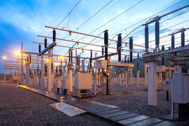
1. What Losses Occur in Both Transformer Types?
Power transformers and distribution transformers operate through electromagnetic induction. Neither transfers all input electrical power to the output because some energy is dissipated as heat, sound, and other minor losses.
The two principal categories are:
- No-load losses (core losses): Losses associated mainly with the magnetic core when the transformer is energized.
- Load losses: Losses that increase with the current flowing through the transformer windings and other conductive components.
Additional losses may arise from stray magnetic fields, dielectric effects, structural components, and auxiliary equipment. Their significance depends on the transformer design, rating, and operating conditions.
Both power transformers and distribution transformers experience no-load losses and load losses.True
Core losses occur when the transformer is energized, while winding and other load-related losses increase with operating current.
2. What Are No-Load Losses in a Transformer?
No-load losses are the losses that occur when a transformer is energized at its rated voltage and frequency, even when its secondary winding supplies little or no load.
The main components are hysteresis loss and eddy-current loss in the magnetic core.
Hysteresis loss occurs because the core material is repeatedly magnetized and demagnetized by the alternating magnetic field. The energy required for each magnetization cycle is partly converted into heat.
Eddy-current loss occurs when the changing magnetic flux induces circulating currents within the core material. These currents generate heat. Transformer cores use thin insulated laminations or other suitable core construction methods to limit these currents.
No-load losses are influenced by core material, magnetic flux density, core geometry, lamination thickness, manufacturing quality, voltage, and frequency.
Because the core remains magnetized whenever the transformer is energized, these losses continue even when the connected load is very small.
3. What Are Load Losses in a Transformer?
Load losses increase as current flows through the transformer windings. The largest component is usually winding resistance loss, commonly called copper loss.
The basic relationship is:
[\P_{\mathrm{winding}}=I^2R]
Where:
- (P_{\mathrm{winding}}) is winding resistance loss in watts
- (I) is winding current in amperes
- (R) is winding resistance in ohms
The square relationship is important. If current increases by 10%, winding resistance loss increases by approximately 21%, assuming resistance remains constant.
Actual load losses can also include stray losses caused by leakage flux inducing currents in windings, tank walls, clamps, and other metallic components. Winding resistance changes with temperature, so loss calculations and factory test results must use the appropriate reference temperature and test method.
Load losses are therefore closely related to the transformer's loading level. A transformer operating at low current generally has lower load losses than the same unit operating near its rated current.
4. How Do Power Transformer and Distribution Transformer Losses Differ?
The main difference is not that one transformer type has a completely different set of losses. Both experience the same fundamental loss mechanisms. The difference lies in how designers prioritize those losses according to the expected operating profile.
Power transformers are commonly used in transmission and substation applications. They may operate at relatively high loading levels for extended periods. Their design therefore places significant emphasis on controlling load losses while maintaining reliable thermal performance.
Distribution transformers often remain energized continuously but experience varying customer demand. They may spend many hours at light load, especially during periods of low residential or commercial consumption. Because core losses continue while the transformer is energized, reducing no-load losses can have a substantial effect on annual energy consumption.
| Comparison factor | Power transformer | Distribution transformer |
|---|---|---|
| Main application | Generation, transmission, and sub-transmission networks | Local distribution and customer supply |
| Typical load pattern | Often substantial and relatively sustained loading, depending on network duty | Frequently variable, with extended light-load periods |
| No-load loss priority | Important because the transformer may remain energized continuously | Particularly important because core losses continue during light-load periods |
| Load loss priority | Often a major design consideration due to high operating current | Important during peak demand and periods of high customer consumption |
| Efficiency assessment | Commonly evaluated against expected high-load and network operating conditions | Should account for daily and seasonal load variation |
| Annual energy impact | Influenced by loading, operating hours, and loss characteristics | Influenced strongly by both energized hours and the changing load profile |
This is a general design distinction, not a rule that every power transformer has lower load losses or every distribution transformer has lower core losses. Actual performance must be established from guaranteed manufacturer data.
5. How Is Transformer Efficiency Calculated?
Transformer efficiency measures the proportion of input power delivered as useful output power.
[\eta=\frac{P_{\mathrm{out}}}{P_{\mathrm{in}}}\times100%]
Because input power equals output power plus losses:
[\eta=\frac{P_{\mathrm{out}}}{P_{\mathrm{out}}+P_{\mathrm{loss}}}\times100%]
Where:
- (\eta) is transformer efficiency
- (P_{\mathrm{out}}) is real output power in watts
- (P_{\mathrm{in}}) is real input power in watts
- (P_{\mathrm{loss}}) is total transformer loss in watts
For a transformer supplying a load at a particular power factor:
[\P_{\mathrm{out}}=S_{\mathrm{out}}\times PF]
Here, (S_{\mathrm{out}}) is output apparent power and (PF) is the load power factor.
Example: Assume a transformer delivers 1,000 kW of real output power and has total losses of 10 kW under the stated operating conditions.
[\eta=\frac{1,000}{1,000+10}\times100%]
[\eta\approx99.01%]
This is an illustrative calculation, not a guaranteed efficiency value for either transformer category. A valid comparison requires measurements or guaranteed loss data at the same rating, voltage, frequency, temperature reference, and loading conditions.
6. How Does Loading Affect Transformer Efficiency?
Transformer efficiency changes with load because core losses and load losses behave differently.
Core losses remain approximately constant when voltage and frequency are maintained near their rated values. Load losses, by contrast, increase approximately with the square of current.
A simplified loss model is:
[\P_{\mathrm{loss}}=P_0+x^2P_k]
Where:
- (P_0) is rated-voltage no-load loss
- (P_k) is load loss at rated current
- (x) is the fraction of rated load current
For example, if a transformer operates at 50% of rated current, its load loss is approximately:
[(0.5)^2P_k=0.25P_k]
This means its load loss is approximately 25% of the rated-current load loss, assuming the same reference conditions and ignoring secondary effects.
The relationship explains why a transformer can have different efficiency values at different loading levels. A design that performs particularly well at full load may not have the lowest annual energy consumption if it operates at light load for much of the year.
7. Why Are No-Load Losses Especially Important for Distribution Transformers?
A distribution transformer is usually energized whenever its local network is in service. Even when few customers are using electricity, the magnetic core remains active and continues to experience core losses.
For this reason, reducing no-load losses can produce significant energy savings over the transformer's operating life.
Consider a simplified annual example:
| Parameter | Transformer A | Transformer B |
|---|---|---|
| No-load loss | 1.2 kW | 1.0 kW |
| Annual energized time | 8,760 hours | 8,760 hours |
| Annual no-load energy loss | 10,512 kWh | 8,760 kWh |
The difference is:
[\10,512-8,760=1,752\text{ kWh per year}]
This example assumes both transformers remain energized for the entire year and that their no-load losses remain constant. It illustrates how a relatively small reduction in continuous core loss can accumulate into meaningful annual energy savings.
For a distribution transformer, buyers should therefore compare guaranteed no-load losses as well as load losses. A lower initial purchase price may not provide the lowest lifetime cost if the unit has higher continuous losses.
8. How Should Buyers Compare Transformer Losses and Efficiency?
A fair comparison should use the manufacturer's guaranteed no-load and load-loss figures rather than relying solely on a general efficiency percentage.
Buyers should request:
| Information to request | What it tells the buyer |
|---|---|
| No-load loss (kW) | Energy consumed by the energized core under specified test conditions |
| Load loss (kW) | Losses at the specified rated current and reference temperature |
| Total loss at a stated load | Expected loss under a particular loading condition |
| Efficiency at specified load points | How efficiently the transformer operates at different loading levels |
| Temperature-rise data | Whether the thermal design meets the specified operating requirements |
| Test conditions and reference temperature | Whether loss figures can be compared accurately |
| Cooling designation and rating | The cooling arrangement and the capacity associated with each rated cooling stage |
| Applicable test standards | The methods used to measure and report losses |
For distribution transformers, buyers should pay particular attention to no-load loss and the annual load profile. For power transformers, the comparison should consider load losses at expected operating levels, annual loading, cooling requirements, and network operating conditions.
Applicable requirements may include the IEC 60076 series or IEEE C57 series, depending on the equipment type, project location, and utility specification. Buyers should confirm the applicable edition and specific contractual requirements rather than assuming that one standard or test applies universally.
9. How Can Buyers Reduce Transformer Losses Over the Operating Life?
Loss reduction begins with correct transformer selection. An appropriately sized transformer avoids unnecessary oversizing while maintaining sufficient capacity for peak demand and expected growth.
Practical measures include:
- Select efficient core materials: Appropriate core steel, magnetic design, and manufacturing quality help reduce no-load losses.
- Control winding resistance: Suitable conductor sizing, winding design, and manufacturing processes help limit load losses.
- Match capacity to the load profile: Consider average demand, peak demand, diversity, and future expansion rather than selecting capacity from connected load alone.
- Maintain cooling systems: Keep radiators, fans, pumps, and ventilation paths in suitable operating condition.
- Monitor loading and temperature: Track current, load variation, ambient conditions, and temperature to identify abnormal operating conditions.
- Evaluate lifecycle cost: Compare initial purchase price, annual energy losses, maintenance, cooling auxiliaries, and expected service life.
For distribution transformers, reducing continuous core losses can be particularly valuable. For power transformers, the economic impact of load losses can be substantial when large amounts of power are transferred for long periods.
Where Are Power Transformers and Distribution Transformers Used in Electrical Power Systems?
Power transformers and distribution transformers are both essential to delivering electricity, but they serve different positions in the electrical power system. Confusing their applications can lead to incorrect equipment specifications, unsuitable voltage levels, unnecessary costs, or unreliable power delivery. To select the right transformer, engineers and buyers need to understand where each type is installed, what voltage transformation it performs, and which network loads it supports.
Power transformers are primarily used at generating stations and transmission or sub-transmission substations to transfer large amounts of electrical power between high-voltage network levels. Distribution transformers are installed closer to electricity users, where they reduce medium-voltage distribution electricity to the low-voltage levels required by homes, commercial buildings, and industrial facilities.
Together, these transformer types form a coordinated voltage-transformation system. This article follows the path of electricity from generation to end users and explains the typical applications, installation locations, and selection considerations for each transformer.
1. Where Are Power Transformers Used in Electrical Power Systems?
Power transformers are commonly installed at major points in the electricity network where large quantities of power need to be transferred between voltage levels. Their main applications include generating stations, transmission substations, sub-transmission substations, and certain large industrial power systems.
1.1 Power Generation Stations
At a generating station, a generator produces electricity at its designed terminal voltage. A generator step-up (GSU) transformer raises this voltage before the electricity enters the transmission network.
Increasing transmission voltage allows a given amount of apparent power to be transferred at a lower current, reducing resistive losses in the transmission conductors. The GSU transformer therefore plays a key role in connecting power plants to the wider grid.
Typical installations include:
- Thermal power stations
- Hydroelectric power plants
- Nuclear generating stations
- Wind power facilities
- Utility-scale solar power plants, where the electrical system requires a suitable step-up transformation
The voltage rating and capacity of a GSU transformer must match the generator, the transmission connection, and the project's operating requirements.
1.2 Transmission Substations
Transmission substations use power transformers to connect different voltage levels within the high-voltage network.
For example, a substation may receive electricity at one transmission voltage and reduce it to another level for onward transmission or sub-transmission. Other substations may perform the reverse transformation when power flow and network configuration require it.
These transformers help utilities manage power flow between network sections, support voltage control, and connect generation and load centers.
1.3 Sub-Transmission Substations
Sub-transmission networks carry electricity from major transmission substations toward regional or local distribution systems. Power transformers at these substations reduce transmission voltage to levels suitable for distribution substations and large customers.
Their capacity and voltage ratings depend on the utility's network design, regional demand, and required redundancy.
1.4 Large Industrial Power Systems
Some large industrial facilities have their own high-voltage substations and use power transformers to supply internal distribution networks.
Examples include:
- Steel and metal processing plants
- Mining and mineral processing facilities
- Large chemical and petrochemical plants
- Data centers
- Large manufacturing campuses
In these applications, the transformer connects the utility supply to the facility's internal voltage levels. The exact equipment classification depends on its rating, network position, and industry or utility terminology.
2. Where Are Distribution Transformers Used?
Distribution transformers are installed closer to end users. Their main function is to reduce medium-voltage electricity from a distribution feeder to the utilization voltage required by customer equipment.
They are found throughout residential, commercial, industrial, and rural distribution networks.
2.1 Residential Areas
In residential networks, distribution transformers supply groups of homes, apartment buildings, or local streets. They reduce the utility's medium-voltage feeder supply to the low-voltage service used by household appliances, lighting, heating, and other electrical equipment.
Common installation arrangements include:
- Pole-mounted transformers in overhead distribution networks
- Pad-mounted transformers in underground distribution systems
- Indoor transformers in suitable building electrical rooms
The transformer rating depends on the expected demand, customer diversity, network design, and future load growth.
2.2 Commercial Buildings
Shopping centers, office buildings, hotels, schools, hospitals, and other commercial facilities may use distribution transformers to provide the voltage required by lighting, HVAC systems, elevators, pumps, and general electrical equipment.
A commercial facility may be supplied by a utility-owned distribution transformer or may have a customer-owned transformer within its electrical installation. The arrangement depends on the utility connection and project design.
2.3 Industrial Facilities
Industrial distribution transformers supply internal low-voltage or intermediate-voltage systems for production machinery, motors, control equipment, lighting, and auxiliary services.
Some industrial sites use several transformers to serve different buildings, production areas, or load groups. Large industrial facilities may also require power transformers at their main substations before distribution transformers supply individual sections of the plant.
2.4 Rural and Remote Networks
Distribution transformers are also used in rural areas, farms, remote communities, and smaller utility networks. They reduce feeder voltage to the levels required by local consumers.
Because rural feeders can be long, engineers must consider voltage drop, load growth, environmental exposure, and maintenance access when selecting and installing distribution transformers.
3. Where Do the Two Transformer Types Fit in the Power System?
A simplified electrical power system shows how power transformers and distribution transformers work together.
- Generation: A power station produces electricity.
- Generator step-up: A power transformer raises the generator voltage.
- Transmission: High-voltage lines carry electricity over long distances.
- Transmission substation: A power transformer changes voltage to another transmission or sub-transmission level.
- Distribution substation: A transformer reduces voltage for medium-voltage distribution feeders.
- Local distribution: Distribution transformers reduce feeder voltage to utilization levels.
- End users: Homes, commercial buildings, and industrial facilities receive electricity at suitable voltages.
\
This sequence is a simplified example. Actual power networks can contain several voltage levels, switching stations, distributed generation connections, and different arrangements for supplying large customers.
4. Power Transformer vs. Distribution Transformer: Application Comparison
| Application or location | Power transformer | Distribution transformer |
|---|---|---|
| Generating station | Commonly used as a generator step-up transformer | Not usually used for the main generator-to-transmission transformation |
| Transmission substation | Commonly used to connect transmission voltage levels | Not normally the primary equipment for bulk transmission transformation |
| Sub-transmission substation | Used to reduce or transform voltage for regional networks | May be used downstream to supply local distribution networks |
| Residential neighborhood | Generally not used for individual local customer supply | Commonly used to supply homes and apartment buildings |
| Commercial building | May supply a large campus or main high-voltage installation | Commonly supplies building utilization voltage |
| Industrial plant | May supply a large industrial substation or internal network | Commonly supplies local plant distribution circuits and equipment |
| Rural distribution network | May be used at major network substations | Commonly supplies local communities, farms, and remote loads |
| Utility-scale renewable project | May be used to connect the project to a transmission or sub-transmission network | May be used within a collector or local distribution arrangement, depending on design |
5. How Do Renewable Energy Projects Use These Transformers?
Renewable energy facilities often use several stages of voltage transformation.
In a wind farm, individual wind turbine generators connect to local electrical collection systems. Transformers associated with the turbines or collection network raise voltage to a medium-voltage level for collection. A main substation may then use a larger power transformer to raise the voltage for connection to the transmission or sub-transmission grid.
Utility-scale solar projects follow a similar principle. Inverter outputs are combined through collection circuits, and transformers provide the voltage levels required by the plant's collector system and grid interconnection.
The exact arrangement depends on the generator or inverter design, collector voltage, grid connection requirements, project capacity, and utility specifications.
Distribution transformers may also be used in smaller renewable energy systems that connect to local distribution networks. In these cases, the transformer must be suitable for the expected direction and characteristics of power flow, protection scheme, and interconnection requirements.
6. What Should Buyers Consider When Selecting a Transformer for These Applications?
The installation location and network function should guide the transformer specification. Buyers should not select a transformer based only on a general label such as power transformer or distribution transformer.
Important considerations include:
| Selection factor | What to verify |
|---|---|
| Application | Generation, transmission, sub-transmission, local distribution, or customer installation |
| Primary and secondary voltage | Rated winding voltages and compatibility with the connected network |
| Rated capacity | Required kVA or MVA, including peak demand and planned expansion |
| Phase configuration | Single-phase or three-phase supply |
| Winding connection | Star, delta, neutral availability, vector group, and phase displacement |
| Impedance | Percentage impedance and its effect on short-circuit current and voltage regulation |
| Insulation level | Maximum system voltage and required power-frequency, switching, and lightning impulse withstand levels |
| Cooling method | Cooling arrangement and rated capacity for each specified cooling stage |
| Installation environment | Indoor or outdoor use, ambient temperature, altitude, pollution, ventilation, and available space |
| Protection and monitoring | Required relays, temperature monitoring, surge protection, and other project-specific provisions |
| Standards and testing | Applicable IEC 60076 or IEEE C57 requirements, utility specifications, and factory acceptance tests |
The final design should be checked against the applicable local electrical codes, utility interconnection requirements, and project specifications. Standards and requirements can vary by location and equipment type, so the exact applicable editions and clauses should be confirmed.
7. What Are Common Transformer Installation Locations?
Transformer installation arrangements are influenced by network voltage, available space, environmental exposure, safety requirements, and maintenance access.
\
For outdoor installations, engineers should evaluate access for transport and lifting, foundation design, electrical clearances, grounding, cable connections, ventilation, fire protection, and liquid containment where applicable.
For indoor distribution transformers, the enclosure, ventilation, noise, fire-safety provisions, access routes, and building requirements must be considered. Dry-type transformers are often selected for certain indoor applications, but they are not automatically fireproof or free from electrical and thermal risks.
How Do Power Transformer and Distribution Transformer Designs Differ in Cooling, Insulation, and Protection?
Choosing between a power transformer and a distribution transformer involves more than comparing voltage ratings and capacity. Their cooling systems, insulation structures, and protective devices must also match their operating conditions. An unsuitable cooling arrangement can cause excessive temperature rise, inadequate insulation can shorten service life, and insufficient protection can expose the transformer and connected equipment to serious electrical faults. Understanding these design differences helps engineers and buyers specify reliable equipment, reduce maintenance risks, and improve long-term operating performance.
Power transformers generally use more extensive cooling, insulation, monitoring, and protection systems because they handle larger power transfers, higher system voltages, and demanding network operating conditions. Distribution transformers usually have simpler, more compact designs suited to local distribution networks, variable customer loads, and installation near end users. However, both types require appropriate thermal management, dielectric insulation, grounding, and fault protection based on their voltage ratings, capacity, installation environment, and applicable standards.
Although both transformer types operate through electromagnetic induction, their engineering designs reflect different electrical and environmental demands. This article compares their cooling methods, insulation systems, and protection arrangements to help buyers understand what matters when specifying either type.
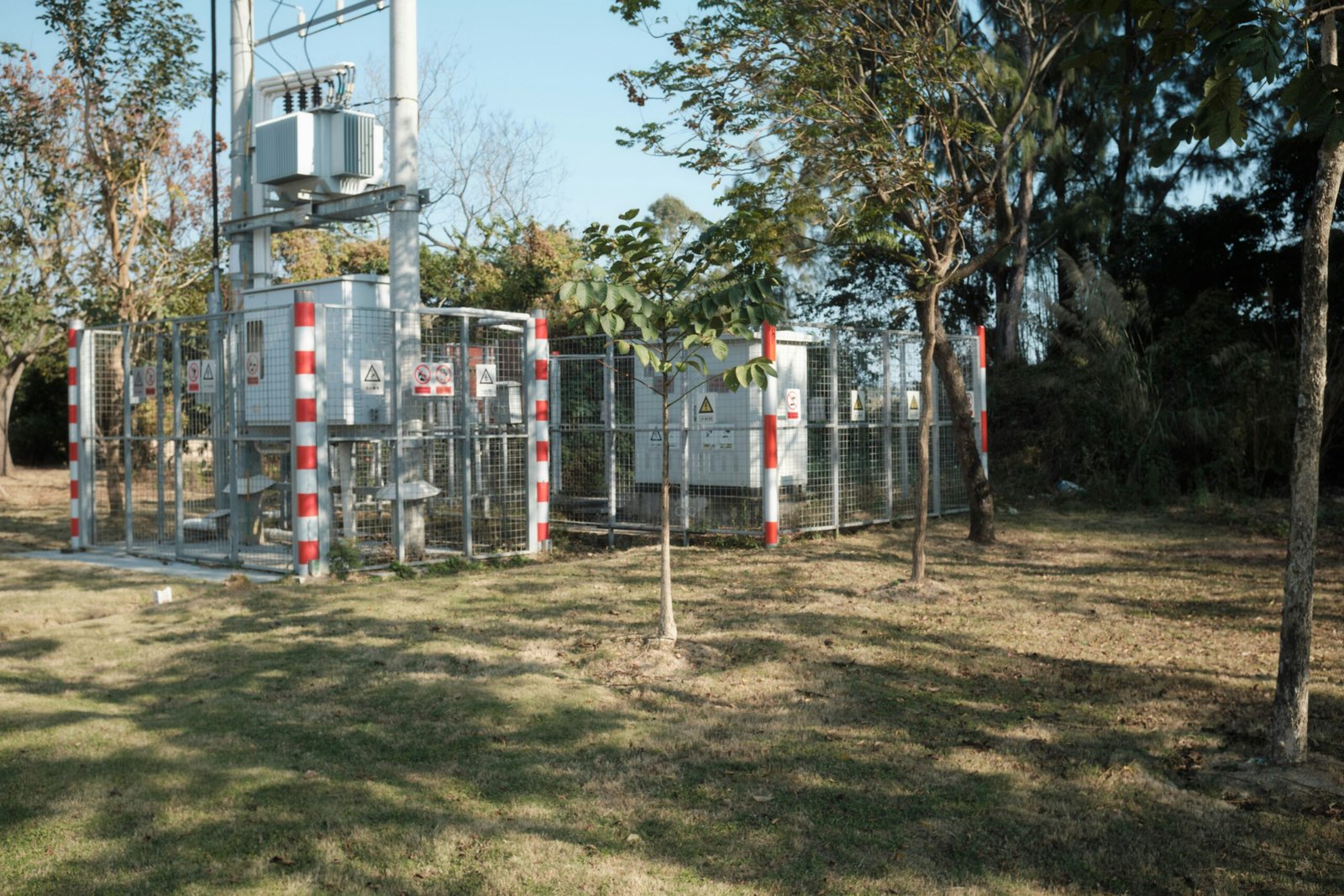
1. How Do Cooling System Designs Differ?
Cooling is essential because electrical losses inside a transformer generate heat. If the temperature of the windings and insulating materials becomes excessive, insulation deterioration accelerates and the transformer's expected service life may be reduced.
Power transformers generally require more extensive thermal management because of their higher ratings and potentially substantial continuous loading. Distribution transformers often use simpler cooling arrangements, although their actual cooling requirements depend on capacity, enclosure design, ambient conditions, and installation location.
1.1 Power Transformer Cooling Systems
Many power transformers use liquid insulation and cooling systems. The insulating liquid transfers heat away from the core and windings toward radiators or heat exchangers, where the heat is released into the surrounding environment.
Common cooling arrangements include:
| Cooling designation | Full description | Basic operating principle |
|---|---|---|
| ONAN | Oil Natural Air Natural | Oil circulates naturally through the transformer and radiators; heat dissipates into natural airflow |
| ONAF | Oil Natural Air Forced | Oil circulates naturally while fans force air across the radiators |
| OFAF | Oil Forced Air Forced | Pumps circulate oil and fans force air across cooling surfaces |
| OFWF | Oil Forced Water Forced | Oil is circulated through a heat exchanger cooled by a forced water system |
A large power transformer may have multiple cooling stages. For example, it may operate with natural cooling under lower loads and activate fans or pumps when additional heat removal is required.
The manufacturer must specify the rated capacity associated with each cooling stage. Adding fans or pumps to a transformer does not automatically authorize an increase in its rated capacity.
1.2 Distribution Transformer Cooling Systems
Distribution transformers generally use simpler cooling systems because their ratings and thermal requirements are often lower than those of major grid transformers.
Common arrangements include:
- ONAN oil-immersed cooling: Natural oil circulation and natural air cooling are widely used in liquid-filled distribution transformers.
- AN dry-type cooling: Natural air circulation removes heat from the windings and core.
- AF dry-type cooling: Fans provide forced airflow to improve heat dissipation when the transformer is specifically designed and rated for this arrangement.
Oil-immersed distribution transformers commonly use corrugated tanks or radiators to increase the surface area available for heat dissipation. Dry-type distribution transformers use air as the cooling medium and may be installed indoors where suitable ventilation and fire-safety provisions are provided.
1.3 Cooling Design Comparison
| Design factor | Power transformer | Distribution transformer |
|---|---|---|
| Typical cooling complexity | May require radiators, fans, pumps, and heat exchangers | Often uses natural oil or air cooling |
| Cooling medium | Commonly insulating liquid and air; some designs use water-cooled heat exchangers | Commonly insulating liquid or air |
| Cooling stages | May have several manufacturer-rated cooling stages | Often has a simpler cooling arrangement |
| Thermal monitoring | May include multiple oil and winding temperature monitoring points | Commonly includes temperature indicators or sensors appropriate to the design |
| Maintenance | May require fan, pump, radiator, heat exchanger, and liquid-system maintenance | Usually focuses on tank condition, ventilation, connections, and liquid or insulation condition |
| Main design priority | Managing heat under high-capacity and demanding operating conditions | Maintaining thermal performance under variable local loading |
A transformer with forced cooling can always operate above its original rated capacity.False
Additional cooling increases permissible capacity only when the transformer is designed, tested, and rated by its manufacturer for the relevant cooling stage and operating conditions.
2. How Do Insulation Designs Differ?
Insulation prevents electrical current from flowing between conductors that should remain electrically separated. It also withstands the electric fields created by operating voltage, switching operations, lightning impulses, and other transient conditions.
Power transformers and distribution transformers both require carefully designed insulation systems, but their insulation levels, clearances, winding arrangements, and dielectric structures vary according to their voltage ratings and operating environments.
2.1 Power Transformer Insulation
Power transformers commonly operate at higher system voltages, so their insulation systems must withstand greater electrical stresses and more demanding insulation-coordination requirements.
Oil-immersed power transformers typically use a combination of:
- Cellulose-based paper insulation around conductors
- Pressboard barriers and spacers between winding sections
- Insulating liquid for dielectric strength and heat transfer
- Insulated winding supports and structural components
- Carefully designed clearances between windings, core, tank, and grounded components
The insulation system must withstand normal operating voltage as well as specified power-frequency, switching impulse, and lightning impulse test levels.
Engineers also consider the transformer's grounding arrangement, system maximum voltage, neutral insulation requirements, and expected transient overvoltages.
Moisture control is particularly important. Water contamination in cellulose insulation can reduce dielectric strength and accelerate insulation aging. Dissolved gas analysis and liquid-quality testing may be used to assess the condition of suitable oil-filled transformers.
2.2 Distribution Transformer Insulation
Distribution transformers also require reliable insulation, but their insulation arrangements are generally more compact because their voltage ratings are usually lower than those of major transmission transformers.
Oil-immersed distribution transformers commonly use insulating paper, pressboard, and dielectric liquid. Dry-type distribution transformers use solid insulation systems, which may include enamel-coated conductors, insulation barriers, resin systems, and suitable insulating materials.
The selection depends on the rated voltage, winding temperature, environmental conditions, enclosure requirements, and installation location.
For example, a dry-type distribution transformer installed inside a commercial building may require a different insulation and enclosure design from an oil-immersed pole-mounted transformer installed outdoors.
2.3 Insulation Design Comparison
| Insulation consideration | Power transformer | Distribution transformer |
|---|---|---|
| Operating voltage | Commonly higher transmission or sub-transmission voltage levels | Commonly medium-voltage primary and low-voltage secondary levels |
| Dielectric design | Often requires more extensive insulation coordination and internal barriers | Designed for the specified distribution voltage and impulse withstand levels |
| Common insulation materials | Cellulose paper, pressboard, insulating liquid, and engineered solid insulation | Paper, pressboard, insulating liquid, resin, and other solid insulation materials |
| Insulation clearances | Carefully engineered for high electrical stress and transient withstand | Designed according to the transformer's voltage class and construction |
| Moisture management | Often involves detailed liquid and solid insulation condition monitoring | Depends on design; may include liquid testing or inspection of solid insulation and enclosure condition |
| Monitoring | May include dissolved gas analysis, moisture monitoring, and other diagnostic methods | May use liquid sampling, insulation testing, temperature monitoring, or condition inspection as appropriate |
The insulation system should be evaluated as a complete design rather than by examining only the insulating liquid or winding material. The interaction between voltage stress, temperature, moisture, mechanical forces, and manufacturing quality determines long-term performance.
3. How Do Protection Systems Differ?
Transformer protection detects abnormal operating conditions and initiates alarms, isolation, or other responses to reduce damage and maintain electrical system safety.
Power transformers generally require more extensive protection because they connect major network sections and may represent a substantial portion of a utility's installed capacity. Distribution transformers use protection appropriate to their ratings, installation arrangements, and the protective devices available in the surrounding network.
3.1 Power Transformer Protection
Power transformers commonly use several complementary protection functions.
Differential protection
Differential protection compares current entering and leaving the protected transformer zone. A significant difference, after accounting for transformer ratio and vector-group compensation, may indicate an internal fault.
Overcurrent and earth-fault protection
These functions detect excessive current and ground-fault conditions. Their settings must coordinate with upstream and downstream protection devices.
Buchholz protection
For applicable conservator-type oil-filled transformers, a Buchholz relay detects gas accumulation and abnormal oil movement associated with certain internal faults. It is not used in every transformer design.
Temperature protection
Winding and oil temperature devices provide alarms or trip signals when specified thermal limits are reached.
Pressure and oil-system protection
Pressure-relief devices and other suitable protective accessories help address abnormal internal pressure. Oil-level monitoring may also be provided where the construction requires it.
Surge protection
Surge arresters and insulation coordination help protect transformer terminals from lightning and switching overvoltages.
Large transformers may also use restricted earth-fault protection, overexcitation protection, cooling-system failure alarms, and other functions depending on the network design.
3.2 Distribution Transformer Protection
Distribution transformer protection is generally simpler but remains essential.
Typical arrangements include:
- High-voltage fuses or other upstream overcurrent protection
- Low-voltage circuit breakers or fuses
- Earth-fault protection where required
- Surge arresters for suitable installations
- Temperature monitoring or protective devices where specified
- Pressure-relief and liquid-level accessories on applicable oil-filled designs
The exact protection arrangement depends on the transformer rating, installation type, utility practice, available fault current, grounding system, and local electrical codes.
A pole-mounted distribution transformer, for example, may use primary fuses and surge arresters coordinated with the upstream feeder. A pad-mounted unit may use compartmentalized equipment and switching or protective arrangements specified for the installation.
3.3 Protection Design Comparison
| Protection function | Power transformer | Distribution transformer |
|---|---|---|
| Differential protection | Common for important or larger units, depending on rating and system requirements | Less common for conventional small distribution units |
| Overcurrent protection | Typically coordinated with network protection systems | Commonly provided through upstream fuses or circuit breakers |
| Earth-fault protection | May include dedicated earth-fault or restricted earth-fault functions | Depends on grounding arrangement and protection scheme |
| Buchholz relay | Used on applicable conservator-type oil-filled designs | Not normally fitted to many conventional sealed distribution designs |
| Temperature protection | Often includes detailed winding and oil temperature monitoring | May use simpler temperature indicators or protective devices |
| Pressure protection | May include pressure-relief and sudden-pressure devices | Pressure-relief devices are used where required by the design |
| Surge protection | Coordinated with high-voltage insulation and system requirements | Commonly uses suitable surge arresters on exposed distribution connections |
| Monitoring | May include advanced online monitoring and diagnostic systems | Often uses more basic monitoring and periodic inspection |
Protection equipment should always be selected and coordinated through an engineering study. Installing individual protective devices without considering fault levels, transformer impedance, grounding, and system coordination may leave equipment inadequately protected.
4. How Do Operating Conditions Influence Cooling, Insulation, and Protection?
The three design areas are closely connected. Cooling controls operating temperature, insulation withstands electrical and thermal stress, and protection helps prevent abnormal conditions from developing into serious damage.
For example, excessive loading increases winding current and load losses. This increases heat generation, which can accelerate insulation aging. Temperature monitoring and suitable protection can help identify abnormal thermal conditions before they cause more extensive damage.
Environmental conditions also matter:
- High ambient temperature: Reduces the temperature difference available for heat dissipation and may limit permissible loading.
- High altitude: Lower air density can reduce the effectiveness of air cooling and affect external insulation performance.
- Humidity and moisture: Can contribute to insulation deterioration, corrosion, and reduced dielectric reliability.
- Dust and pollution: May contaminate external insulation surfaces and affect ventilation.
- Coastal or corrosive environments: May require enhanced coatings, corrosion-resistant components, and more frequent inspections.
- Frequent load fluctuations: Can create thermal cycling and affect winding and insulation aging.
- Lightning and switching activity: Can increase transient electrical stress and influence surge protection and insulation coordination.
A transformer designed for a clean indoor electrical room may not be appropriate for an exposed outdoor substation without modifications to its enclosure, insulation, cooling, and environmental protection.
5. What Should Buyers Check When Comparing Transformer Designs?
Buyers should request technical documentation covering the complete cooling, insulation, and protection arrangements. A general description such as oil-immersed, dry-type, or high-efficiency is not sufficient to establish whether a transformer meets the project's requirements.
| Technical item | Information to verify | Why it matters |
|---|---|---|
| Cooling designation | ONAN, ONAF, OFAF, OFWF, AN, AF, or the applicable manufacturer designation | Confirms the cooling arrangement |
| Cooling-stage capacity | Rated kVA or MVA at each approved cooling stage | Prevents incorrect assumptions about available capacity |
| Temperature rise | Winding and liquid temperature-rise limits under specified conditions | Confirms thermal design suitability |
| Insulation level | Rated voltage, maximum system voltage, and impulse withstand levels | Confirms dielectric compatibility |
| Insulation materials | Liquid, paper, pressboard, resin, and other specified materials | Helps assess design and maintenance requirements |
| Protection accessories | Differential, overcurrent, earth-fault, temperature, pressure, and other applicable functions | Confirms protection coverage |
| Monitoring equipment | Temperature indicators, gas monitoring, oil-level devices, and online diagnostics where required | Supports condition assessment |
| Factory testing | Applicable routine, type, and special tests | Provides evidence of design and manufacturing quality |
| Environmental suitability | Ambient temperature, altitude, pollution, corrosion, and enclosure requirements | Confirms suitability for the installation site |
| Standards compliance | Applicable IEC 60076 or IEEE C57 requirements and local project specifications | Establishes the relevant technical and testing framework |
IEC 60076 and IEEE C57 are important transformer standards families, but the specific applicable parts and editions depend on transformer type, design, and project location. Buyers should confirm contractual requirements with the engineer, utility, and manufacturer.
6. How Can Proper Design Improve Transformer Reliability?
Reliable transformer performance depends on matching the complete design to the actual operating environment.
For power transformers, buyers should pay particular attention to cooling-stage ratings, insulation coordination, internal fault protection, online monitoring requirements, and maintenance accessibility. Because these units may serve critical network functions, the consequences of an unexpected outage can be significant.
For distribution transformers, the priorities often include suitable natural or forced cooling, appropriate insulation for the voltage class, effective feeder protection, environmental resistance, and ease of maintenance or replacement.
Good engineering practice includes:
- Matching transformer capacity to the expected load profile.
- Selecting a cooling system suitable for rated operation and site conditions.
- Specifying insulation levels based on maximum system voltage and transient requirements.
- Coordinating fuses, circuit breakers, relays, and surge arresters with the electrical network.
- Establishing inspection, testing, and maintenance procedures.
- Reviewing factory test reports and technical documentation before acceptance.
How Do You Choose Between a Power Transformer and a Distribution Transformer for Your Project?
Selecting the wrong transformer type can create costly problems throughout an electrical project. A transformer designed for local distribution may not meet the capacity and operating requirements of a transmission substation, while an unnecessarily large power transformer can increase initial investment, installation complexity, and maintenance costs. The challenge is not simply choosing between two transformer sizes; it is identifying the equipment that matches your network position, voltage requirements, load characteristics, and operating environment. By evaluating these factors systematically, buyers can select a transformer that delivers reliable performance and economical operation over its service life.
Choose a power transformer when your project requires large-scale power transfer between generation, transmission, or sub-transmission voltage levels, typically at high MVA ratings. Choose a distribution transformer when your project requires reducing medium-voltage distribution electricity to low-voltage levels for residential, commercial, or local industrial loads. The final selection should be based on network function, voltage ratings, required capacity, load profile, cooling, insulation, protection, installation conditions, and applicable standards—not capacity alone.
Although power transformers and distribution transformers perform the same fundamental voltage-transformation function, their designs and operating duties differ. This guide provides a practical selection process to help project owners, electrical engineers, contractors, and procurement teams identify the appropriate transformer before requesting quotations or placing an order.
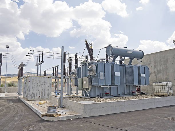
1. Start by Identifying Your Project's Electrical Application
The first and most important selection step is identifying where the transformer will operate in the electrical power system.
A transformer should be selected according to its role in the network rather than its appearance, physical dimensions, or general capacity.
When Should You Choose a Power Transformer?
A power transformer is generally appropriate when your project involves large-scale electricity transfer between generation, transmission, and sub-transmission networks.
Typical applications include:
- Power generation stations: Generator step-up transformers increase generator voltage before electricity enters the transmission network.
- Transmission substations: Transformers connect different transmission voltage levels.
- Sub-transmission substations: Transformers reduce voltage for regional distribution networks.
- Large industrial substations: High-capacity transformers supply major industrial facilities and internal electrical networks.
- Renewable energy projects: Main transformers connect utility-scale wind and solar installations to transmission or sub-transmission systems.
Power transformers are generally designed for high voltage ratings, substantial MVA capacities, demanding insulation requirements, and comprehensive monitoring and protection arrangements.
When Should You Choose a Distribution Transformer?
A distribution transformer is generally appropriate when your project requires the final voltage conversion between a medium-voltage distribution network and customer utilization equipment.
Typical applications include:
- Residential neighborhoods and apartment developments
- Commercial buildings and shopping centers
- Schools, hospitals, and office complexes
- Manufacturing facilities and smaller industrial plants
- Farms, rural communities, and remote distribution networks
- Local distribution systems connected to renewable energy installations
Distribution transformers are commonly installed closer to customers and are available in pole-mounted, pad-mounted, and indoor configurations.
A transformer should be classified as a power transformer or distribution transformer based only on its rated MVA capacity.False
The distinction primarily reflects the transformer's application and operating role in the electrical network. Capacity is an important specification, but it does not establish a universal classification boundary.
2. Compare Primary and Secondary Voltage Requirements
Voltage compatibility is one of the most important technical selection criteria.
A power transformer may connect a generator to a high-voltage transmission network or transform between two grid voltage levels. A distribution transformer generally receives medium-voltage feeder electricity and supplies low-voltage utilization power.
The correct primary and secondary voltage ratings must match the actual electrical system.
| Voltage consideration | Power transformer | Distribution transformer |
|---|---|---|
| Primary voltage | Commonly high-voltage or extra-high-voltage network levels, depending on application | Commonly medium-voltage distribution feeder levels |
| Secondary voltage | Another transmission, sub-transmission, or large industrial voltage level | Usually low-voltage utilization or local distribution level |
| Main function | Bulk power transfer and grid voltage transformation | Final voltage reduction for customer supply |
| Insulation requirements | Often requires extensive insulation coordination for high system voltage | Designed for the applicable distribution voltage class |
| Common applications | Generating stations and grid substations | Residential, commercial, and local industrial networks |
For example, a project connecting a generator to a high-voltage grid may require a power transformer with a generator-side voltage matching the generator terminals and a grid-side voltage matching the transmission connection.
By contrast, a commercial building receiving medium-voltage utility power may require a distribution transformer to provide the low-voltage supply used by its electrical equipment.
Important: Do not select a transformer based only on nominal voltage. Confirm the maximum system voltage, frequency, grounding arrangement, winding connections, insulation level, and required tap range.
3. Calculate the Required Transformer Capacity
After identifying the application and voltage levels, determine the transformer's required rated capacity.
Transformer capacity is expressed in kVA or MVA because it represents apparent power rather than real power alone.
For a single-phase transformer:
[\S=VI]
For a balanced three-phase transformer:
[\S=\sqrt{3}\times V_{LL}\times I_L]
Where:
- (S) = apparent power in VA
- (V_{LL}) = line-to-line voltage in volts
- (I_L) = line current in amperes
The relationship between real power and apparent power is:
[\P=S\times PF]
Where (PF) represents power factor.
Practical Capacity Selection Example
Suppose an industrial facility has an estimated maximum real power demand of 800 kW and an expected power factor of 0.90.
The required apparent power is:
[\S=\frac{800}{0.90}=888.9\text{ kVA}]
A preliminary selection might consider a standard transformer rating above this calculated demand, subject to load characteristics, ambient temperature, harmonics, motor starting, future expansion, and the manufacturer's rating conditions.
The same calculation principle applies to power transformers and distribution transformers. What changes is the scale of the project and the network operating requirements.
4. Understand the Differences in Load Profiles
Transformer capacity should not be selected using connected load alone. Engineers need to understand when and how the electrical load operates.
Power transformers often transfer substantial power for extended periods, although their actual loading varies with generation dispatch, network demand, and contingency conditions.
Distribution transformers commonly experience more pronounced daily and seasonal load fluctuations. For example, a residential distribution transformer may experience a significant evening peak, while its average demand throughout the day is considerably lower.
| Load characteristic | Power transformer project | Distribution transformer project |
|---|---|---|
| Main load concern | Bulk power flow and network operating duty | Local customer demand and demand diversity |
| Loading pattern | May be relatively sustained or vary with network dispatch | Frequently fluctuates throughout the day |
| Peak demand | Must accommodate network maximum and specified contingency conditions | Must accommodate local coincident peak demand |
| Future expansion | Consider grid development and generation or industrial growth | Consider additional customers and increased local consumption |
| Overload assessment | Requires thermal and system contingency evaluation | Requires load-cycle and thermal assessment |
Buyers should provide the manufacturer with a realistic load profile rather than relying on a single estimated demand figure.
5. Compare Cooling, Insulation, and Protection Requirements
Cooling, insulation, and protection must be considered together because they determine whether a transformer can operate safely under its expected electrical and environmental stresses.
Cooling Requirements
Power transformers may require multiple cooling stages, including radiators, fans, pumps, or heat exchangers. Distribution transformers commonly use simpler natural oil or air cooling arrangements.
Typical designations include:
| Cooling designation | Description | Typical application |
|---|---|---|
| ONAN | Oil Natural Air Natural | Oil-immersed power and distribution transformers |
| ONAF | Oil Natural Air Forced | Transformers designed for fan-assisted cooling |
| OFAF | Oil Forced Air Forced | Certain large oil-immersed power transformers |
| OFWF | Oil Forced Water Forced | Certain large transformers using water-cooled heat exchangers |
| AN | Air Natural | Dry-type transformers with natural air cooling |
| AF | Air Forced | Dry-type transformers designed for forced-air cooling |
The manufacturer's specified rating for each cooling stage must be checked. Forced cooling should not be assumed to increase the rated capacity unless the transformer is designed and rated accordingly.
Insulation Requirements
Power transformers generally require more extensive insulation coordination because of their higher operating voltages and exposure to switching and lightning transients.
Distribution transformers also require reliable insulation, but their insulation structures are usually designed around lower distribution voltage classes.
Buyers should confirm:
- Rated voltage and maximum system voltage
- Power-frequency withstand level
- Lightning impulse withstand level where applicable
- Winding insulation arrangement
- Insulating liquid or dry-type insulation system
- Temperature-rise requirements
- Moisture protection and environmental suitability
Protection Requirements
Power transformers may require differential protection, overcurrent protection, earth-fault protection, temperature monitoring, pressure protection, and other network-specific functions.
Distribution transformers commonly use coordinated primary fuses or circuit breakers, secondary protection, surge arresters, and appropriate temperature or pressure accessories.
The final protection scheme should be designed around available fault current, transformer impedance, grounding arrangements, and coordination with upstream and downstream devices.
6. Consider Installation Location and Environmental Conditions
The installation environment can significantly influence the transformer's construction and performance.
A power transformer installed outdoors at a transmission substation may require a substantial foundation, transport access, electrical clearances, liquid containment, cooling equipment, and extensive maintenance access.
A distribution transformer installed on a utility pole or concrete pad requires a different mechanical and environmental design.
Consider the following factors before choosing:
| Environmental factor | Selection consideration |
|---|---|
| Indoor or outdoor installation | Select an appropriate enclosure, insulation system, and cooling arrangement |
| Ambient temperature | Confirm permissible loading and temperature-rise performance |
| Altitude | Evaluate cooling effectiveness and external insulation requirements |
| Humidity and moisture | Specify suitable protection and insulation condition controls |
| Dust and pollution | Consider enclosure protection, ventilation, and external insulation performance |
| Coastal or corrosive environments | Evaluate coatings, corrosion-resistant materials, and maintenance needs |
| Available space | Check transformer dimensions, access, clearances, and lifting requirements |
| Noise restrictions | Confirm acceptable sound levels for residential or commercial locations |
| Fire safety | Evaluate liquid type, containment, separation, and applicable fire-protection requirements |
For indoor installations, dry-type transformers may be appropriate where liquid containment or particular building requirements influence the design. However, dry-type construction does not mean that a transformer is fireproof or requires no ventilation.
7. Evaluate Efficiency and Total Lifecycle Cost
Initial purchase price is only one part of transformer ownership cost.
Both power transformers and distribution transformers experience no-load losses and load losses. However, their expected loading patterns influence which loss components deserve particular attention.
Power transformers may operate at relatively high loading levels for long periods, making load losses an important economic consideration.
Distribution transformers can remain energized throughout the year while operating at light load for substantial periods. Their continuous no-load losses can therefore have a significant effect on annual energy consumption.
A practical lifecycle assessment should include:
- Purchase and transportation costs
- Installation and commissioning costs
- No-load losses
- Load losses at expected operating conditions
- Cooling auxiliary energy consumption
- Routine inspection and maintenance
- Spare parts and repair costs
- Expected service life and outage consequences
A simplified annual energy-loss calculation is:
[\E_{\mathrm{loss}}=P_0t+P_kx^2t]
Where:
- (E_{\mathrm{loss}}) = approximate annual energy loss in kWh
- (P_0) = no-load loss in kW
- (P_k) = rated-current load loss in kW
- (x) = fraction of rated current
- (t) = operating hours
This simplified equation assumes a constant loading fraction and does not account for changes in winding resistance, voltage, temperature, or cooling auxiliary consumption. For an actual project, engineers should use an hourly or representative load profile and the manufacturer's guaranteed loss data.
8. Verify Applicable Standards and Factory Testing
Before purchasing either transformer type, confirm that its design and manufacturing tests meet the applicable project requirements.
Relevant standards families include:
- IEC 60076 series: Power transformer requirements and associated testing.
- IEEE C57 series: Transformer standards covering various design, testing, and application topics.
The exact standard, edition, and clauses depend on the transformer type, location, utility requirements, and project specification.
Buyers should request the following documents where applicable:
- Approved technical datasheet and general arrangement drawing.
- Rated voltage, capacity, frequency, phase, and vector group details.
- Impedance and insulation-level information.
- Cooling designation and rated capacity for each cooling stage.
- Guaranteed no-load and load losses.
- Routine factory test reports.
- Applicable type and special test reports.
- Protection and accessory documentation.
- Installation, operation, and maintenance instructions.
- Quality and compliance documentation required by the contract.
Factory acceptance testing should be agreed before production or purchase order approval. The scope may include winding resistance, voltage ratio, polarity or vector group, impedance and load loss, no-load loss and current, dielectric tests, and additional project-specific tests.
9. Practical Decision Guide: Which Transformer Is Right for Your Project?
The following table summarizes the main selection scenarios.
| Project requirement | Recommended transformer category | Main reason |
|---|---|---|
| Generator connection to transmission grid | Power transformer | Raises generator voltage for bulk power transfer |
| Transmission voltage conversion | Power transformer | Connects different high-voltage network levels |
| Regional substation supply | Usually power transformer | Transfers large power to sub-transmission or distribution networks |
| Residential neighborhood supply | Distribution transformer | Provides low-voltage electricity to homes |
| Commercial building receiving medium-voltage supply | Distribution transformer | Reduces feeder voltage to building utilization voltage |
| Local manufacturing facility | Usually distribution transformer | Supplies plant loads at the required utilization voltage |
| Large industrial high-voltage substation | Power transformer, potentially followed by distribution transformers | Connects the utility network to internal industrial distribution |
| Utility-scale renewable energy grid connection | Often a combination of transformer types | Provides voltage transformation at collection and grid-interconnection stages |
Some projects require both transformer categories. For example, a large industrial campus may receive high-voltage utility power through a power transformer and then use several distribution transformers to supply buildings and production areas.
The selection should therefore reflect the complete electrical architecture rather than assuming that one transformer type must serve every voltage-conversion stage.
10. What Information Should You Prepare Before Requesting a Quotation?
Providing accurate project information helps manufacturers recommend a suitable transformer and reduces unnecessary specification revisions.
Prepare the following information:
- Project type and application
- Primary and secondary rated voltages
- Rated capacity in kVA or MVA
- Single-phase or three-phase configuration
- Frequency: 50 Hz or 60 Hz
- Required winding connections and vector group
- Percentage impedance, if specified
- Insulation level
- Cooling method
- Indoor or outdoor installation
- Ambient temperature and site altitude
- Load profile and expected future expansion
- Efficiency or guaranteed loss requirements
- Protection and monitoring requirements
- Applicable standards and factory testing requirements
If some parameters have not yet been finalized, provide the available electrical drawings, utility requirements, and load information. The manufacturer's engineering team can help identify the remaining design decisions.
Conclusion
Power transformers and distribution transformers serve different but complementary roles in electrical power systems. Power transformers support high-voltage power transmission and large-scale energy transfer, while distribution transformers deliver electricity at usable voltage levels to commercial, industrial, and residential consumers. The right choice depends on the network position, voltage requirements, load profile, rated capacity, efficiency targets, and installation conditions.
FAQ
Q1: What is the main difference between a power transformer and a distribution transformer?
A power transformer transfers electrical energy at high voltage levels, mainly in generation and transmission networks. A distribution transformer reduces voltage to levels suitable for commercial, industrial, and residential consumers.
Q2: Where are power transformers and distribution transformers used?
Power transformers are commonly installed at power plants, transmission substations, and major grid interconnections. Distribution transformers are used near end users, including residential neighborhoods, commercial buildings, and industrial facilities.
Q3: Which transformer is more efficient?
Both are designed for high efficiency, but their operating conditions differ. Power transformers typically operate near rated load, while distribution transformers may remain energized throughout the day with varying loads. Therefore, distribution transformer design places particular emphasis on reducing no-load losses.
Q4: What is the difference in voltage ratings?
Power transformers generally handle higher transmission and sub-transmission voltages, often ranging from tens to hundreds of kilovolts. Distribution transformers typically reduce medium-voltage electricity to low-voltage levels, such as 400/230 V or 480/277 V, depending on regional standards.
Q5: How do you choose between a power transformer and a distribution transformer?
Choose based on the electrical system's function, voltage requirements, load capacity, installation location, efficiency targets, cooling method, and applicable standards. Power transformers suit transmission and major substations, while distribution transformers serve local power delivery.
References
- IEC 60076-1 — Power Transformers: General
https://webstore.iec.ch/en/publication/588 - IEC 60076-2 — Power Transformers: Temperature Rise
https://webstore.iec.ch/en/publication/604 - IEC 60076-3 — Power Transformers: Insulation Levels and Dielectric Tests
https://webstore.iec.ch/en/publication/605 - IEC 60076-5 — Power Transformers: Ability to Withstand Short Circuit
https://webstore.iec.ch/en/publication/607 - IEEE C57.12.00 — General Requirements for Liquid-Immersed Distribution, Power, and Regulating Transformers
https://standards.ieee.org/ieee/C57.12.00/6962/ - IEEE C57.12.01 — General Requirements for Dry-Type Distribution and Power Transformers
https://standards.ieee.org/ieee/C57.12.01/6775/ - IEEE C57.12.80 — Terminology for Power and Distribution Transformers
https://standards.ieee.org/ieee/C57.12.80/7006/ - IEEE C57.12.36 — Liquid-Immersed Distribution Substation Transformers
https://standards.ieee.org/ieee/C57.12.36/11334/ - IEEE Technology Navigator — Power Transformers
https://technav.ieee.org/topic/power-transformers/ - U.S. Department of Energy — Electricity Delivery and Grid Systems
https://www.energy.gov/oe