Traction Transformer

Overview

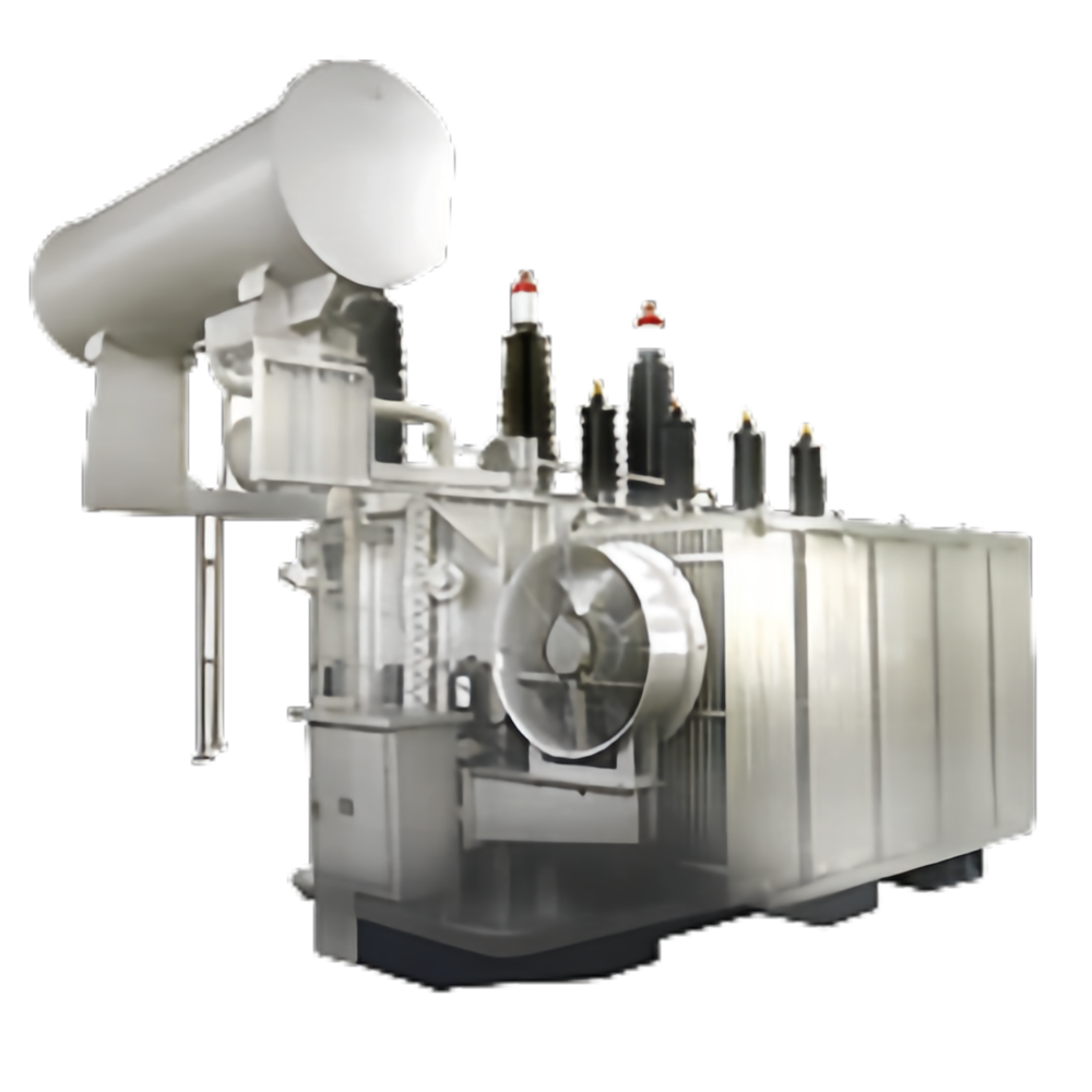
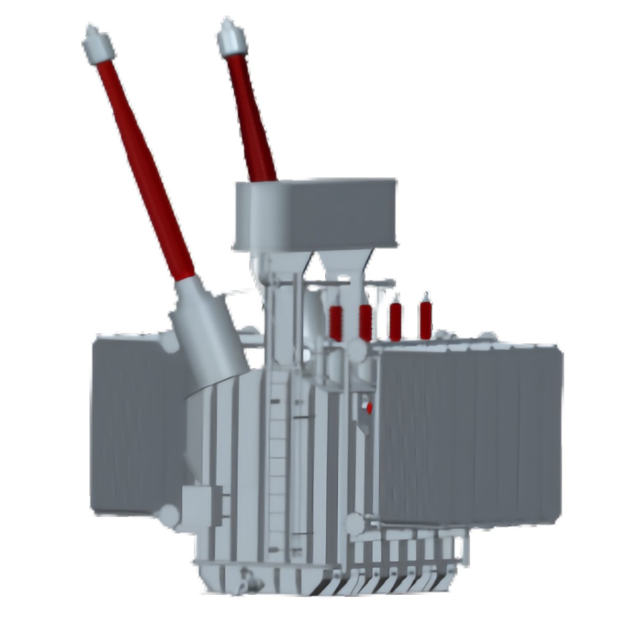
In order to meet the needs of railway electrification development demand for electrified railway traction transformer special service conditions, combined with our company 500kV power transformer technology advantage and improve production quality assurance system, using the electromagnetic field, temperature field, fluid leakage magnetic field, and other professional technical analysis software company perfect, successfully developed a single-phase auto traction transformer 110kV single-phase traction substation, railway traction transformer, three-phase VV connected balance traction transformer and 220kV single-phase traction transformer, three-phase VX connected traction transformer. This series of products have the characteristics of short circuit capacity, over load capacity, low noise, low temperature rise and high reliability.
Trusted by world-class brands & organizations of all sizes

Product Feature

1. Railway traction autotransformer

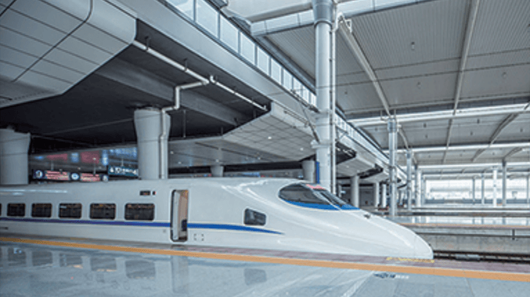
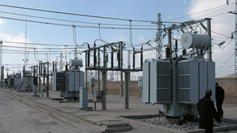
Railway traction autotransformer is applied to the electrified railway AT power supply mode, and has good anti-interference performance. It can eliminate or weaken the interference caused by the electrical interference source.
  • Low short-circuit impedance

The magnitude of short circuit impedance is an important index to measure the performance of single-phase autotransformer.

In the calculation of short-circuit impedance, our company can control the short-circuit impedance to the lowest level by using electromagnetic simulation software. Converted to the low voltage side, the short-circuit reactance meets <0.45Ω.

  • Strong short circuit resistance and high overload capacity

The transformer is a low impedance transformer, and its short-circuit current and short-circuit mechanical force increase remarkably compared with the common transformer.

In order to ensure that the transformer has enough anti short circuit capability, our company developed the autotransformer traction transformer with short circuit resistance of mature technology, from design, process has taken corresponding measures, greatly improving the product and short circuit ability.

According to the load curve compiled over load capacity temperature analysis software customers and electrified railway standards, strictly abide by the relevant provisions, calculated according to the corresponding calculation method, which can meet the load curve of temperature rise, and have a certain degree of safety.

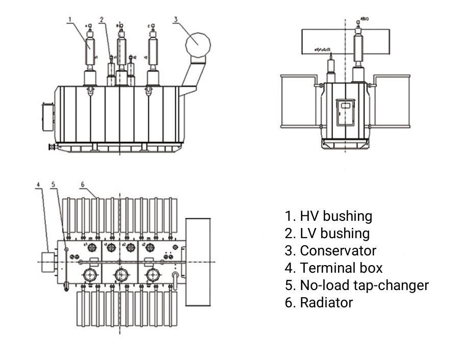
Outline drawing of railway auto-transformer

Technical parameter list of railway auto-transformer

Type Rated Capacity (kVA)Rated Voltage (kV) Connection Group Rated Frequency (Hz)No-load Loss (kW)No-load Current (%)Low Side Leakage Reactance (Ω)Cooling MethodWeight (t)Overall Dimension (mm)
OD-QY-20000/2×27.5200002×27.5/27.5Ia0508.50.35<0.45ONAN Total: 20.5L: 3450  W: 3700 H: 4300
OD-QY-25000/2×27.5250002×27.5/27.5Ia050100.35<0.45ONAN Total: 23.5L: 3600  W: 3750 H: 4300
OD-QY-31500/2×27.5315002×27.5/27.5Ia050120.4<0.45ONAN Total: 26L: 3700  W: 3800  H: 4200
OD-QY-40000/2×27.5400002×27.5/27.5Ia050140.35<0.45ONAN Total: 29L: 3800  W: 4200  H: 4300
OD-QY-50000/2×27.5500002×27.5/27.5Ia050170.25<0.2ONAN Total: 33L: 4000  W: 4700 H: 4400
OD-QY-63000/2×27.5630002×27.5/27.5Ia050200.2<0.2ONAN Total: 37.5L: 4100  W: 4800  H: 4550

Note:

  1. The above data for selection reference, our company reserves the right to amend;
  2. It can provide the corresponding parameter product according to the customer request.

2. VX traction transformer for railway

VX railway traction transformer is developed in recent years, a new type of railway traction transformer to adapt to the development of China high-speed railway, which is used for AT power supply mode, relative to other transformer AT power supply mode has obvious advantages, the capacity utilization rate is high, the level of high voltage power supply arm; compared with the pure single-phase traction transformer, can make the negative in order to reduce by half the effect. It has a wide application prospect.
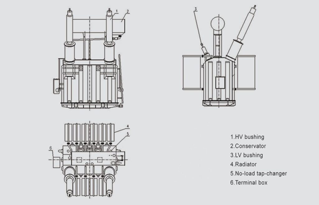
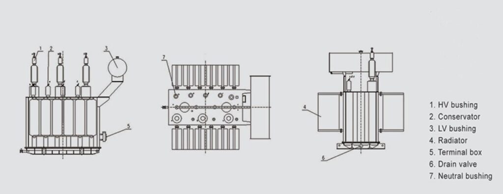
Outline drawing of VX traction transformer for railway

The unique advantages of VX traction transformer for railway

Simple structure and flexible collocation

Two low voltage secondary winding capacity of flexible configuration, we can design different capacity according to the requirements of different lines; The structure can use two independent single-phase traction transformer, three-phase VX connected traction transformer split by external, and can also use the two single-phase transformers in the same tank in the three-phase VX form traction transformer.

Suitable for the development of electrified high speed railway

Strong power supply capacity, long distance power supply, traction substation location convenient and less quantity of AT power supply, it can reduce the external power input, with excellent anti jamming effect, reducing the number of phase separation, conducive to the safe operation of the locomotive. The utility model is particularly suitable for the development of electrified high-speed railways in China, and has broad application prospects.

Good short circuit withstand and high overload capacity

The transformer for low impedance transformer, compared with ordinary transformer, short-circuit current and short circuit mechanical force increases significantly. In order to ensure that the transformer has enough anti short circuit capability, our company developed the traction transformer with short circuit resistance of mature technology, and has taken corresponding measures from design, process, and greatly improves the product anti short circuit ability.

According to the load curve compiled over load capacity temperature analysis software of customers and electrified railway standards, we strictly abide by the relevant provisions, calculated according to the corresponding calculation method, which can meet the load curve of temperature rise, and have a certain degree of safety.
3. Railway balance traction transformer

  • Simple structure
    The high voltage side is a star connection, and the neutral point can be led out, which adapts to the 110kV grounding system. The two side has a triangle circuit, which can suppress the higher harmonics and improve the power supply quality.
  • Simple impedance matching and good balance
    When the two phase side load is equal, the three-phase side is symmetrical; the three-phase side load is unequal, the three-phase side balance greatly improves and eliminates the influence of the negative sequence current on the power system, and has no interference to the communication line.
  • High efficiency
    The primary side of the transformer in three phase power completely into the secondary side of the two phase power, compared with the same nominal capacity transformer, can improve the efficiency of about 1.25 times.
  • Less investment
    The triangular draw out of the low voltage side of the transformer can provide the reactive compensation interface, and the voltage level of the electric equipment is decreased, and the equipment input cost is lowered

4. VV coupling traction transformer

  • Simple structure and convenient connection
    Three-phase VV rail traction transformer place two separate magnetic single-phase double-winding transformers in one tank. Two single-phase transformer primary windings series wiring, the two ends and the middle of the series as a primary side of the three-phase power input, both head and tail of two single-phase transformer secondary winding are leading out. It can be conveniently connected to Vv0 or Vv6 binding line according to the design requirements for use.
  • Flexible capacity collocation, high utilization rate

Composed of two single-phase transformer capacity of three-phase VV connection flexible collocation, can be the same or different, so the transformer capacity idle, the utilization rate of capacity can reach 100%, saving investment and operating costs.
  • Simple structure of the traction power supply system
    The traction substation obtains the electric energy from the power system, and then it is directly supplied to the traction network after the voltage transformation. The rectifier and frequency conversion equipment are not needed in the substation, and the structure of the substation is greatly simplified.
  • Simple structure of the traction power supply system
    The anti short circuit technology of our company mature VV traction transformer is our company developed a three-phase VV railway, according to the operating characteristics of the product, from the aspects of design and technology has taken corresponding measures, winding all semi hard copper wire, greatly improves the product anti short circuit ability.

Technical Parameters

Traction Transformer Technical Parameters

Technical parameter list of railway auto-transformer

Type Rated Capacity (kVA)Rated Voltage (kV) Connection Group Rated Frequency (Hz)No-load Loss (kW)No-load Current (%)Low Side Leakage Reactance (Ω)Cooling MethodWeight (t)Overall Dimension (mm)
OD-QY-20000/2×27.5200002×27.5/27.5Ia0508.50.35<0.45ONAN Total: 20.5L: 3450  W: 3700 H: 4300
OD-QY-25000/2×27.5250002×27.5/27.5Ia050100.35<0.45ONAN Total: 23.5L: 3600  W: 3750 H: 4300
OD-QY-31500/2×27.5315002×27.5/27.5Ia050120.4<0.45ONAN Total: 26L: 3700  W: 3800  H: 4200
OD-QY-40000/2×27.5400002×27.5/27.5Ia050140.35<0.45ONAN Total: 29L: 3800  W: 4200  H: 4300
OD-QY-50000/2×27.5500002×27.5/27.5Ia050170.25<0.2ONAN Total: 33L: 4000  W: 4700 H: 4400
OD-QY-63000/2×27.5630002×27.5/27.5Ia050200.2<0.2ONAN Total: 37.5L: 4100  W: 4800  H: 4550

Note:

  1. The above data for selection reference, our company reserves the right to amend;
  2. It can provide the corresponding parameter product according to the customer request.

Please contact us for parameter information.

Please contact us for parameter information.

Please contact us for parameter information.

Contact us to upgrade or install your energy system.

QC & Guarantee

Market Orientation and Service Commitment

In response to fierce market competition and to meet customer demands, our company adheres to a market-oriented approach and a customer-centric philosophy. We have earned widespread recognition from our clients through efficient, comprehensive services and superior product quality.

Our Commitments

  1. Product Lifespan Guarantee: The operational lifespan of our transformers is no less than 30 years.
  2. Strict Quality Control:
    • Upon receiving bid documents, we promptly initiate the evaluation process to ensure all customer requirements are fully addressed.
    • We carefully select certified suppliers and strictly follow quality management standards to control and inspect raw materials and components.
    • We produce high-quality, customer-satisfactory parts in full compliance with contract and technical agreement requirements.
  3. After-Sales Service Commitment:
    • All performance indicators and technical specifications of our transformers meet or exceed national standards.
    • Within 3 years of installation and commissioning, if any oil leakage occurs due to manufacturing defects in oil-immersed transformers, we will repair it at no cost.
    • For any critical component defects identified during production or issues discovered during installation, we prioritize resolution to meet project timelines, followed by thorough responsibility analysis and necessary repairs or replacements.
    • We welcome customers to supervise the manufacturing process at our facility and will provide full support.

After-Sales Support

We offer comprehensive after-sales services, including free guidance for installation and commissioning. After the product is operational, if the customer requires support, our service team will respond promptly:

  • Arrival on-site within 24 hours for locations within 300 km.
  • Arrival on-site within 48 hours for locations beyond 300 km.

Additionally, we have established a robust regular follow-up system. We conduct periodic written or on-site visits to monitor the performance of in-service products, ensuring our customers have continuous peace of mind.

International Service Methods

Remote Technical Assistance

Our service team provides 24/7 online technical support, including video calls, troubleshooting guides, and documentation, ensuring immediate assistance regardless of time zones.
Detailed remote diagnostics can be conducted using customer-provided data or live visual inspections.

On-Site Support

For complex issues, we dispatch experienced technicians to the customer site promptly, adhering to the agreed international response timelines.
On-site services include installation guidance, commissioning, maintenance, and repairs.

Dedicated Service Representatives

Each international client is assigned a dedicated service representative to coordinate all aspects of after-sales support, including issue resolution and regular follow-ups.

Local Service Partnerships

We collaborate with certified local service partners in key markets to ensure faster response times and efficient support. These partners are fully trained in our products and processes to uphold our quality standards.
Regular Follow-Up Visits

Post-installation, we perform scheduled follow-up visits, either in person or virtually, to monitor product performance and address customer feedback. This proactive approach ensures optimal operation and customer satisfaction.

Why This Matters

Our comprehensive international service system combines swift response, advanced technical support, and localized expertise to provide our global clients with reliable and professional after-sales services. We are committed to building lasting partnerships through consistent support and excellence.

FAQs

Traction Transformer FAQs

When purchasing a Traction Transformer, you may want to know the following questions & answers.

A Traction Transformer is a vital component used in electric railways, metro systems, and high-speed trains, converting high-voltage electrical energy to a lower voltage suitable for traction motors and other electrical systems. The technical specifications of a traction transformer depend on various factors, including the type of system, rail voltage levels, and the specific design required for the application.

Here are the key technical specifications and voltage ratings you can expect for a traction transformer:

1. Primary Voltage (High Voltage Side):

The primary voltage is the voltage supplied to the transformer from the power grid or overhead lines, typically ranging from:

  • 15 kV, 16.7 Hz (AC) — This is common for European railway networks, such as Germany and Switzerland.
  • 25 kV, 50/60 Hz (AC) — Widely used in many regions worldwide (e.g., USA, UK, and other parts of Europe and Asia).
  • 1.5 kV DC / 3 kV DC — Common for urban railways, including metro and light rail systems, where direct current is used.

2. Secondary Voltage (Low Voltage Side):

The secondary voltage is the voltage output used for the traction motors and other electrical systems onboard trains or vehicles. Typical secondary voltages are:

  • 600 V to 3,000 V (DC) — For systems that use DC traction motors.
  • 1,000 V to 1,500 V (AC) — For AC-fed systems, common in modern locomotives and multiple units.

3. Power Rating:

The power rating is the maximum load that the traction transformer can handle. This is typically measured in MVA (Mega Volt-Amperes) or kVA (Kilo Volt-Amperes), with values varying based on the system’s needs:

  • 1 MVA to 10 MVA for light rail or tram systems.
  • 10 MVA to 50 MVA for standard regional trains or metro systems.
  • 50 MVA to 100 MVA and higher for high-speed trains and heavy freight locomotives.

4. Frequency:

  • For AC systems, transformers are designed for either 50 Hz or 60 Hz depending on the region.
  • For DC systems, the transformer frequency is typically not applicable as it operates in a direct current mode.

5. Impedance and Regulation:

The impedance of a traction transformer is generally in the range of 5-10% depending on the system design and the application, as this affects how the voltage is regulated under different load conditions. Traction transformers are designed to ensure stable voltage under high load demands, which are common in rail applications.

6. Cooling:

Traction transformers are generally cooled using oil or air:

  • Oil-immersed transformers use oil for insulation and cooling.
  • Air-cooled transformers may be used for smaller systems or in applications with space constraints.

7. Construction Type:

  • Core-type and shell-type designs are both common, with core-type being more frequent in rail traction due to better handling of high power and mechanical stresses.
  • Enclosures are typically sealed to prevent contamination, ensuring long operational life.

8. Protection and Safety Features:

  • Overcurrent protection
  • Overvoltage protection
  • Temperature sensors
  • Insulation monitoring
  • Ground fault protection

9. Efficiency and Losses:

Traction transformers are designed with high efficiency, often exceeding 98% to minimize energy loss, with both no-load losses and load losses being considered in their design.

10. Enclosure and Size:

  • Outdoor or indoor installations: Traction transformers can be built for harsh environments, with weatherproof enclosures when installed outdoors.
  • Dimensions and weight: Vary according to power ratings but can be large, with weight typically ranging from 10 tons to over 50 tons depending on the size and rating.

11. Voltage Regulation:

  • Automatic Tap Changers (ATC): Some traction transformers use tap-changing mechanisms to adjust the voltage as required.
  • Voltage regulation needs to be tightly controlled to maintain stable operation of the traction system, especially during acceleration or when load conditions change rapidly.

Example of a Traction Transformer Specification:

  • Primary Voltage: 25 kV, 50 Hz (AC)
  • Secondary Voltage: 1,500 V DC
  • Power Rating: 25 MVA
  • Impedance: 6%
  • Cooling: Oil-immersed
  • Weight: ~30 tons
  • Efficiency: 98.5%

In summary, traction transformers are designed to handle high electrical loads, provide stable power output to traction motors, and ensure the safety and reliability of the train’s electrical system. Voltage ratings and technical specifications can vary depending on the geographical area and the specific rail system’s requirements.

Yes, Traction Transformers are designed and built in compliance with various international standards to ensure safety, reliability, and interoperability across different rail systems and regions. Compliance with standards such as IEC, ANSI, and others is critical for ensuring that the transformers meet the electrical, mechanical, and safety requirements for rail applications. Here are the main standards and certifications that are commonly associated with traction transformers:

1. IEC Standards (International Electrotechnical Commission)

The IEC is the leading global organization for setting electrical and electronic standards. Traction transformers are typically designed to meet the following IEC standards:

  • IEC 60076: This is the primary standard for the design, testing, and operation of power transformers. Specific parts of this standard apply to traction transformers:

    • IEC 60076-1: General rules and definitions for power transformers.
    • IEC 60076-11: Requirements for transformers used in railway applications.
    • IEC 60076-3: Determination of temperature rise and testing methods for traction transformers.
    • IEC 60076-16: Part 16 covers the application guide for traction transformers, including guidelines on electromagnetic compatibility (EMC), thermal management, and environmental considerations.
  • IEC 61378: This standard specifically applies to traction transformers used in electric railways and tram systems. It provides guidance on performance requirements, design, and testing of transformers for use in railway traction systems.

  • IEC 60947: Low-voltage switchgear and controlgear, which includes transformers in the scope for applications involving low-voltage components and protections used in railway electrification.

  • IEC 62271: High-voltage switchgear and controlgear standards, especially for transformers in high-voltage railway applications.

  • IEC 61810-1: Standards for electromechanical relays, applicable when relays are used in traction transformer protection systems.

2. ANSI Standards (American National Standards Institute)

The ANSI standards, used primarily in North America, are also applicable to traction transformers, especially for systems that adhere to American or Canadian railway systems. Relevant ANSI standards include:

  • ANSI C57 Series: These are the standards for transformers in North America, similar to IEC standards, focusing on the design, testing, and operational parameters.

    • ANSI C57.12.00: General requirements for transformers.
    • ANSI C57.12.90: Tests for transformers, including dielectric testing and short circuit withstand capacity.
    • ANSI C57.12.91: Environmental considerations and standards for transformer construction.
  • ANSI C37.90: This standard relates to surge protection and electrical testing standards, critical for transformers used in areas with potential for electrical surges or faults.

  • ANSI/IEEE C57.109: Specific guidance on protection, including fault tolerance and load regulation, relevant for transformers used in heavy-duty applications like traction systems.

3. Other International Standards and Certifications

Depending on the region and application, traction transformers may also comply with various additional standards and certifications, such as:

  • IEEE Standards: These standards are used mainly in the United States but are influential globally. They focus on transformer design, testing, and materials.

    • IEEE C57.12: Related to transformer standards, including load testing, cooling methods, and impedance values for traction transformers.
  • UL Standards: In North America, transformers used in rail applications often comply with Underwriters Laboratories (UL) safety standards for electrical equipment.

    • UL 1446: Insulation systems used in transformers.
    • UL 506: Provides guidelines for low-voltage transformers, including specifications for control circuits.
  • EN Standards (European Norms): These standards are widely used across Europe:

    • EN 60076: Translates IEC 60076 into the European regulatory framework.
    • EN 50163: Specifies voltage limits for electric railway systems.
    • EN 50329: Provides requirements for traction transformers, focusing on the technical and safety requirements.
  • ISO Certifications: Manufacturers often obtain ISO 9001 (Quality Management Systems) and ISO 14001 (Environmental Management) certifications to ensure that their transformers are manufactured according to high-quality standards and sustainable practices.

4. EMC and Environmental Considerations

  • Electromagnetic Compatibility (EMC): Traction transformers must comply with EMC standards to minimize electromagnetic interference (EMI) with surrounding equipment. These include compliance with IEC 61000 and EN 55011.
  • Environmental Standards: Compliance with environmental standards, such as RoHS (Restriction of Hazardous Substances) and REACH (Registration, Evaluation, Authorisation, and Restriction of Chemicals), may also be required, particularly when transformers are deployed in environmentally sensitive areas or urban environments.

5. Safety and Reliability Standards

  • Traction transformers must adhere to stringent safety standards, such as those set out in IEC 61508 (Functional Safety) or IEC 62061 (Safety of machinery). These standards ensure the operational safety and reliability of transformers in railway applications, especially in terms of protection against faults and failures during operation.

Summary of Key Compliance Areas:

  • IEC 60076 (general transformer standards) and IEC 61378 (specific to traction transformers).
  • ANSI C57 (for North American systems).
  • EN 50163 (European railway standards for traction systems).
  • EMC and environmental standards (for minimizing interference and ensuring eco-friendly operation).
  • ISO 9001 (quality management) and ISO 14001 (environmental management) certifications.

Conclusion:

Traction transformers are indeed compliant with a wide range of international standards, including IEC, ANSI, and ISO, among others. These standards ensure that the transformers are safe, reliable, efficient, and suitable for use in the demanding environments of rail systems worldwide. Compliance with these standards helps ensure that traction transformers can operate across various regions and meet specific national or regional regulatory requirements.

The efficiency and energy losses of a Traction Transformer are critical factors in determining the overall performance, energy consumption, and operational costs of electric railways, metros, and high-speed trains. Since traction transformers play a central role in converting electrical energy from the overhead lines or third rail to the required voltage levels for traction motors and onboard systems, their efficiency is paramount to minimize waste and improve system sustainability.

1. Efficiency Levels of Traction Transformers

The efficiency of a Traction Transformer is typically high, as they are designed for maximum performance under constant high-load operation. The efficiency is primarily determined by the ratio of output power to input power. This ratio is influenced by various factors, including load conditions, transformer design, cooling system, and the type of materials used.

  • Typical Efficiency Range:
    • For oil-immersed traction transformers, the efficiency typically ranges between 98% and 99% under normal operating conditions.
    • For air-cooled traction transformers, the efficiency can be slightly lower, ranging between 97% and 98% depending on size and load conditions.

Factors Affecting Efficiency:

  • Load Conditions: Efficiency tends to be highest when transformers are operating near their full-rated load. The efficiency decreases slightly at lower loads due to the core losses (no-load losses) and other inherent transformer characteristics.
  • Voltage Regulation: High-quality transformers are designed with good voltage regulation, ensuring minimal losses under varying load conditions. Proper voltage regulation helps maintain efficiency even during load fluctuations.
  • Cooling Methods: Oil-cooled transformers are more efficient at handling higher loads and dissipating heat compared to air-cooled ones, as oil has a higher heat capacity.
  • Transformer Design and Material: The design of the core and winding (e.g., high-quality silicon steel, copper windings) and the manufacturing quality impact both the efficiency and the energy losses.

2. Energy Losses in Traction Transformers

Energy losses in a traction transformer can be broadly categorized into two main types: core losses (no-load losses) and copper losses (load losses).

A. Core Losses (No-Load Losses):

Core losses, also known as no-load losses, occur in the transformer’s magnetic core due to the continuous magnetization and demagnetization process in AC transformers. These losses are relatively constant and do not depend on the load, but rather on the voltage applied to the transformer.

  • Cause: These losses are caused by the hysteresis and eddy currents in the transformer’s core, which is typically made of laminated silicon steel.
  • Magnitude: Core losses typically range from 0.1% to 0.5% of the rated power capacity of the transformer.
    • For a 25 MVA transformer, this could equate to 25 kW to 125 kW.
  • Influence of Load: Since core losses are largely independent of the load, they remain relatively constant during operation, which means they always exist regardless of whether the transformer is loaded or idle.

B. Copper Losses (Load Losses):

Copper losses occur due to the resistance in the transformer windings when electric current flows through them. These losses are proportional to the square of the current, meaning they increase with higher load currents.

  • Cause: These losses are mainly due to the resistance of the windings (typically copper or aluminum) and the magnetic flux induced by the current passing through the transformer.
  • Magnitude: Copper losses are dependent on the load and can vary significantly. Under full load conditions, they can be in the range of 0.2% to 0.8% of the rated power.
    • For example, in a 25 MVA transformer, the copper losses under full load could range from 50 kW to 200 kW.
  • Load-Dependent: As the load decreases, the copper losses decrease exponentially (since they depend on the square of the current). Thus, copper losses are minimized when the transformer operates at light loads.

C. Other Losses:

In addition to core and copper losses, traction transformers may experience other minor losses:

  • Stray Losses: These losses occur due to leakage flux that induces eddy currents in the transformer’s structural components, such as the tank and metallic frame.
  • Dielectric Losses: These losses result from the dielectric materials (insulation) used in the transformer and typically account for a small fraction of the total losses.
  • Cooling Losses: For oil-cooled transformers, energy is consumed in the cooling process. These losses are related to the efficiency of the cooling system (e.g., fans, pumps) and the heat dissipation rate.

3. Losses at Various Load Conditions

The total losses in a traction transformer depend on the load factor, i.e., how much of the transformer’s rated capacity is being utilized. These losses are typically tested at multiple load levels to establish performance:

  • At Full Load: Total losses (core + copper + stray) typically range from 1% to 2% of the transformer’s rated power.

    • For a 25 MVA transformer, this would result in 250 kW to 500 kW of total losses.
  • At 75% Load: The total losses reduce due to the decrease in copper losses, though core losses remain constant. In this case, the total losses might be around 0.8% to 1.5% of the rated power.

  • At 50% Load: Further reduction in copper losses leads to a more favorable efficiency, but core losses still remain the same. Total losses can fall to 0.6% to 1.2%.

  • At Light Load or Idle: The copper losses are minimal, but core losses dominate. Total losses might range from 0.5% to 1%.

4. Energy Losses per Year

The energy losses over a year depend on the average load the transformer operates at, the total operating hours, and the efficiency. For example, if a 25 MVA transformer operates at an average load of 60% over a year (8,000 operating hours), and assuming total losses are about 1.5% of rated power:

  • Energy Losses per Year = 25 MVA×1.5%×8000 hours25 \, \text{MVA} \times 1.5\% \times 8000 \, \text{hours} = 3,000 MWh per year (3,000,000 kWh).

This is the amount of energy lost as heat, which would need to be dissipated via the cooling system.

5. Improving Efficiency

Modern traction transformers are designed to minimize losses through various techniques, such as:

  • Low-loss materials: High-grade electrical steel for the core and high-conductivity copper for windings.
  • Optimized cooling: Effective oil or air cooling designs to manage losses more efficiently.
  • Tap changers: Automatic tap changers for maintaining voltage regulation and minimizing losses during load variations.
  • Efficient design: Advanced computational modeling to optimize transformer geometry and minimize stray losses.

Summary:

  • Efficiency: Traction transformers typically have an efficiency range of 98% to 99%, with oil-immersed transformers being slightly more efficient than air-cooled ones.
  • Core (No-Load) Losses: Typically 0.1% to 0.5% of rated power.
  • Copper (Load) Losses: Typically 0.2% to 0.8% of rated power, increasing with load.
  • Total Losses: At full load, total losses usually range from 1% to 2% of the rated power capacity.

Reducing energy losses and improving transformer efficiency helps lower operational costs, minimize environmental impact, and enhance the sustainability of rail transportation systems.

In traction transformers, cooling is a critical factor to ensure efficient operation and to prevent overheating during high-load conditions. The cooling system is designed to dissipate the heat generated by core losses (no-load losses) and copper losses (load losses). These transformers are subjected to varying loads, and efficient cooling is essential for maintaining optimal performance and reliability.

The cooling system used in traction transformers depends on the size, design, and application. Generally, the most common cooling methods for traction transformers are:

1. ONAF Cooling System

ONAF stands for Oil Natural, Air Forced. This is one of the most widely used cooling methods for large oil-immersed traction transformers.

  • Oil Natural (ON): The transformer’s core and windings are immersed in transformer oil, which acts as both an insulating and cooling medium. The oil absorbs the heat generated by the transformer and rises due to its expansion when heated. As it rises, it flows through the transformer, carrying the heat away from the windings and core.
  • Air Forced (AF): To improve heat dissipation, fans are used to force air over the transformer’s radiators or fins. The oil inside the transformer circulates naturally (due to convection), but the forced air helps to cool the oil more effectively and speeds up the heat transfer process.

Advantages:

  • Efficient for large transformers.
  • Good for applications with high load and continuous operation, such as traction transformers used in railway and metro systems.
  • Relatively simple and cost-effective for high-power transformers.

Typical Use: Large traction transformers with power ratings ranging from 10 MVA to over 100 MVA often use the ONAF system, particularly in environments where high-efficiency cooling is required to handle large amounts of heat dissipation.

2. OFAF Cooling System

OFAF stands for Oil Forced, Air Forced. This system is similar to ONAF, but with a more active cooling approach for the oil circulation.

  • Oil Forced (OF): In this case, the transformer oil is actively pumped through the transformer windings and core by an oil pump. This ensures more efficient circulation of oil, improving the heat exchange between the core and windings and the oil.
  • Air Forced (AF): Just like in the ONAF system, fans are used to force air over the radiators or cooling fins to dissipate the heat from the oil.

Advantages:

  • More efficient than ONAF for transformers requiring high cooling capacities, especially under heavy load conditions.
  • Active circulation of oil ensures better cooling and lower operating temperatures.
  • Provides better heat dissipation compared to ONAF, particularly when the transformer operates at high capacities for extended periods.

Typical Use: The OFAF system is often used in very large traction transformers (typically above 50 MVA) and in applications where the transformer must operate at higher temperatures and under more demanding conditions, such as high-speed trains and heavy freight locomotives.

3. ONAN Cooling System

ONAN stands for Oil Natural, Air Natural. This is the simplest cooling system where the transformer relies entirely on natural processes for cooling.

  • Oil Natural (ON): The transformer is oil-immersed, and heat is transferred from the core and windings to the oil. The oil then rises naturally due to the heat, causing convection currents that circulate the oil within the transformer tank.
  • Air Natural (AN): The oil is cooled by radiators or fins that are naturally ventilated by the surrounding air. There are no fans to force the air, and the process relies entirely on the natural convection of both the oil and the air.

Advantages:

  • Simple, cost-effective, and reliable for smaller transformers.
  • Fewer moving parts (no fans or pumps), leading to lower maintenance needs.
  • Suitable for smaller transformers or those with lower power ratings.

Typical Use: This system is most commonly used in smaller traction transformers (less than 10 MVA) or in applications where the heat generation is lower, and passive cooling is sufficient.

4. OFWF Cooling System

OFWF stands for Oil Forced, Water Forced. This system uses water to assist in cooling the oil in the transformer, rather than air.

  • Oil Forced (OF): The transformer oil is actively circulated, typically using a pump.
  • Water Forced (WF): Instead of using air, water is circulated through the heat exchangers or coolers (called oil-water heat exchangers) to remove heat from the transformer oil. Water has a higher thermal conductivity than air, which makes it a more effective cooling medium for large transformers.

Advantages:

  • More effective cooling compared to air, especially in applications with high continuous loads.
  • Often used for high-power transformers where oil and air cooling is not sufficient, and water cooling offers a more compact and effective solution.

Typical Use: This system is used in very large traction transformers, typically in situations where higher reliability and cooling capacity are required, and where cooling via air is insufficient, such as for high-speed trains, substations, or heavy-duty rail applications.

5. Other Cooling Methods:

Some advanced traction transformers may use other specialized or hybrid cooling techniques, including:

  • Gas Cooling (CO2 or SF6): Although not as common in traction transformers, in some specialized applications or substation transformers, gases like CO2 or SF6 might be used for insulation and cooling, particularly for high-voltage transformers.
  • Hybrid Cooling: Combining oil, water, and air cooling for maximum heat dissipation in extreme environments or for applications requiring the highest reliability.

Summary of Cooling Systems in Traction Transformers:

Cooling SystemTypeKey FeaturesTypical Use
ONAFOil Natural, Air ForcedNatural oil circulation with forced air cooling.Standard for medium to large traction transformers (10–100 MVA).
OFAFOil Forced, Air ForcedActive oil circulation with forced air cooling.Large traction transformers (above 50 MVA) requiring higher cooling capacities.
ONANOil Natural, Air NaturalNatural oil circulation with natural air cooling.Smaller traction transformers or those with lower power requirements (up to 10 MVA).
OFWFOil Forced, Water ForcedActive oil circulation with water cooling.Very large traction transformers, typically high-power (above 50 MVA).

Conclusion:

The cooling system of a traction transformer plays a key role in ensuring its efficiency, longevity, and reliability. The choice of cooling method (ONAF, OFAF, ONAN, or OFWF) depends on the transformer’s size, the operating conditions, and the cooling requirements. For most high-power traction transformers, ONAF and OFAF systems are the most common due to their efficiency in handling large amounts of heat, while ONAN is used for smaller transformers. OFWF cooling systems are typically reserved for high-performance applications where advanced cooling is needed to handle the highest thermal loads.

The expected lifespan of a traction transformer under normal operating conditions typically ranges between 30 to 40 years, though this can vary depending on several factors such as design, operating environment, and maintenance practices.

Key Factors Influencing the Lifespan:

  1. Quality of Design and Materials:

    • Core and winding materials: High-quality materials, such as copper windings and silicon steel core laminations, contribute to longer operational life. Using advanced materials can improve resistance to wear and tear over time.
    • Insulation systems: The transformer’s insulation plays a major role in its longevity. Oil (in oil-immersed transformers) and solid insulation materials (such as paper or synthetic insulations) must withstand high electrical stresses, heat, and moisture for the transformer to last.
  2. Load Conditions:

    • Traction transformers are typically designed for heavy-duty cycling, as they operate under varying loads, with frequent start-ups, stops, and changes in demand. However, overloading can significantly shorten their lifespan.
    • Continuous high-load operation can stress the transformer’s core and windings, accelerating wear.
    • Transformer efficiency (high efficiency = less heat generation) also affects longevity. Transformers operating near their optimal load tend to have a longer life than those consistently running at full load or higher than designed limits.
  3. Operating Environment:

    • Ambient temperature: Transformers operating in environments with high ambient temperatures can experience increased core and winding losses, which can cause thermal aging of the insulation.
    • Moisture and contaminants: Exposure to moisture, dirt, or corrosive gases can degrade the oil (in oil-cooled transformers) and insulation, leading to shorter lifespans.
    • Vibration and mechanical stresses: Transformers used in rail systems may face mechanical stresses, particularly in areas with high vibrations or frequent changes in load.
  4. Cooling Efficiency:

    • Effective cooling (whether through ONAF, OFAF, or OFWF systems) helps dissipate the heat generated by the transformer. Poor cooling performance due to blocked radiators, damaged fans, or inadequate oil circulation can cause overheating, increasing thermal stresses and reducing the transformer’s life.
    • Transformer oil should be regularly tested and maintained (by checking dielectric strength and moisture levels) to ensure it remains effective in insulating and cooling the system.
  5. Maintenance Practices:

    • Regular inspection and maintenance play a crucial role in ensuring the transformer’s longevity. Key maintenance activities include:
      • Oil testing (for oil-filled transformers): Checking for acidity, moisture, and dissolved gases.
      • Tap changer maintenance: Ensuring that the tap changers (especially on-load tap changers (OLTC)) are functioning correctly and are not causing excessive wear.
      • Routine testing (e.g., insulation resistance, power factor testing) to detect early signs of wear or faults.
    • Preventive maintenance can extend the lifespan significantly by identifying problems like insulation degradation, leakage, or corrosion before they cause major failures.
  6. Transformer Design Features:

    • Modern transformers may include advanced monitoring systems (such as temperature sensors, humidity sensors, and dissolved gas analysis) that help identify issues early and prevent major failures. Such features contribute to extending the operating life of the transformer.

Typical Lifespan Range:

  • Under Normal Operating Conditions: The typical lifespan of a traction transformer is 30 to 40 years. This assumes the transformer operates within its design parameters, with appropriate load, cooling, and maintenance.

  • Well-Maintained Transformers: With good maintenance practices and optimal operating conditions, traction transformers can sometimes exceed the typical lifespan, potentially reaching 45 to 50 years or more.

  • Heavy Load or Extreme Conditions: If the transformer operates at higher loads or in harsher environmental conditions (e.g., high temperature, corrosive environments), the lifespan could be closer to 30 years.

Conclusion:

The expected lifespan of a traction transformer, when properly maintained and operating under normal conditions, is typically between 30 to 40 years. However, with careful design, regular maintenance, and optimal operating conditions, it is possible to extend this lifespan further, sometimes up to 50 years or more. Key factors influencing lifespan include quality of materials, cooling system performance, operating load, and environmental conditions. Regular inspections, oil testing, and monitoring systems play an essential role in achieving the full service life.

Traction transformers, like all electrical transformers, are equipped with various safety features to prevent overloading and short-circuiting, both of which can lead to catastrophic failures, equipment damage, and safety hazards. These safety mechanisms are designed to protect the transformer, maintain reliable operation, and ensure the safety of the overall system. Below are the main safety features typically incorporated in traction transformers:

1. Overload Protection:

Overloading occurs when the transformer is subjected to higher electrical loads than it is designed for, which can lead to overheating, insulation degradation, and potential failure. To prevent this, the following features are used:

A. Overload Relays

  • Thermal Overload Relays: These devices monitor the temperature and current within the transformer. When the transformer exceeds a predefined thermal limit (usually based on the transformer’s design capacity), the overload relay will disconnect the transformer from the circuit to prevent further damage.
  • Current Relays: These relays monitor the current flowing through the transformer. If the current exceeds the safe rated limit (often a multiple of the rated current), the relay activates to interrupt the power supply, preventing overloads.
  • Time-Current Characteristic Protection: Some relays provide protection based on time and current, allowing transformers to handle short-term overloads but disconnecting after the overload persists beyond a safe duration.

B. On-Load Tap Changer (OLTC) Protection

  • Load-Sensing Tap Changers: The transformer may include on-load tap changers (OLTC) that adjust the voltage by changing the taps on the transformer’s windings. OLTCs are equipped with current sensors that can detect overloads or abnormal current flows. If an overload is detected, the tap changer can adjust the voltage to balance the load and avoid excessive current.
  • Tap Changer Protection Devices: These devices detect faults or abnormal conditions (such as excessive current or short-circuit) at the tap changer and immediately trigger a disconnection or bypass to prevent damage to the transformer.

2. Short-Circuit Protection:

Short-circuits (whether internal or external) can cause high fault currents that can quickly destroy the transformer windings, insulation, and other components. To protect against short-circuits, the following safety features are typically included:

A. Fuses and Circuit Breakers

  • High-Voltage Fuses: Transformers often have fuses installed to protect the windings against short-circuit currents. Fuses are designed to blow when the current exceeds a certain threshold, disconnecting the transformer from the power supply. The fuses may be located on the primary side (high voltage) or secondary side (low voltage) depending on the transformer design.
  • Circuit Breakers: Circuit breakers are used for more reliable and automated disconnection in the event of a short circuit. These are typically installed in the primary circuit or feeder lines and provide fast fault detection and cutoff to prevent damage to the transformer. Modern circuit breakers often have vacuum or SF6 insulation, which allows for very fast arc quenching and high reliability.
    • Instantaneous Trip Function: Some breakers are designed with an instantaneous trip function, which detects short-circuit conditions and disconnects the transformer almost immediately.
    • Inverse Time Delay: For smaller fault currents, breakers can feature an inverse time delay, which allows a small fault current to clear over time, but trips faster for larger faults.

B. Differential Protection

  • Differential Protection is one of the most common and reliable methods for detecting short circuits. It compares the incoming current to the outgoing current in the transformer. In a healthy transformer, the input and output currents are equal. However, in the case of a short circuit, there will be a discrepancy between the two, and the differential protection system will immediately isolate the transformer from the circuit.
  • High-Speed Relays: These relays operate quickly (within milliseconds) and are often used in conjunction with differential protection to minimize damage during short-circuit events.

3. Overcurrent Protection

Overcurrent protection mechanisms prevent the transformer from being exposed to excessive currents, whether due to a short circuit or overload. The following systems are employed to provide overcurrent protection:

A. Overcurrent Relays

  • These relays detect when the current exceeds the safe rated value of the transformer and will trip the transformer’s circuit breaker to disconnect the transformer from the electrical network.
  • Inverse Time Overcurrent Relays: These relays are commonly used to protect against prolonged overcurrent situations. The relay’s trip time is inversely proportional to the magnitude of the overcurrent. The greater the current, the quicker the transformer is disconnected, preventing prolonged damage.

B. Backup Protection (Time-Delayed)

  • In case the primary protection fails, backup protection with time-delay can be used to ensure the transformer is isolated if a fault or overload persists. Backup protection is typically set with a delay to allow for coordinated tripping of other system components.

4. Pressure Relief Devices and Explosion Protection

Oil-filled transformers are susceptible to internal faults that could lead to a pressure rise, especially during faults like short circuits or overloading, which can generate excessive heat or gas. To protect the transformer from overpressure and possible explosions:

A. Pressure Relief Valve (PRV)

  • Oil-immersed transformers typically include pressure relief valves (PRV). If internal pressure rises above a certain threshold due to fault conditions (such as gas accumulation from an internal fault), the PRV will open, allowing gases to escape safely and preventing catastrophic failure.

B. Explosion Vent

  • In certain designs, an explosion vent is provided to release gases from the transformer in a controlled manner to prevent internal pressure buildup that could cause an explosion. This vent is designed to open under extreme pressure conditions, releasing gases to prevent rupture of the tank.

5. Temperature Protection

  • Temperature sensors are often installed on various parts of the transformer (windings, oil) to monitor the temperature. These sensors are connected to an alarm or protection relay. If the transformer temperature exceeds safe operating limits, these systems will activate to reduce the load, shut down the transformer, or trigger cooling mechanisms.
  • Thermal Overload Protection: Transformers are equipped with thermal overload protection that activates when the temperature exceeds safe operating limits, either by controlling the load or triggering disconnection.

6. Earth Fault Protection

  • Earth Fault Relays are used to detect and protect against earth faults (i.e., when a live conductor comes into contact with the ground or the transformer’s body). The relay detects an imbalance between the current in the phase conductors and the earth conductor and trips the transformer to prevent damage and ensure safety.

7. Grounding and Insulation Protection

  • Grounding: Traction transformers are grounded through neutral grounding resistors or directly grounded to prevent dangerous potentials and ensure safe operation.
  • Insulation Monitoring: Advanced insulation monitoring systems continuously check the insulation resistance, and if the resistance falls below a certain threshold (indicating a potential failure), the system can raise an alarm or initiate protective measures to avoid short-circuiting or ground faults.

8. Buchholz Relay (in Oil-Immersed Transformers)

  • Buchholz relays are used in oil-filled transformers to detect internal faults, such as gas accumulation due to overheating or arcing inside the transformer. The Buchholz relay detects the buildup of gas or oil movement caused by a fault and activates an alarm or trips the circuit breaker, preventing further damage.

Conclusion:

Traction transformers are equipped with multiple layers of protection to prevent overloading and short-circuiting, ensuring safe, reliable, and efficient operation. These protections include:

  • Overload protection (relays, thermal sensors, and tap changer adjustments),
  • Short-circuit protection (fuses, circuit breakers, and differential protection),
  • Overcurrent protection (relays with time-current characteristics),
  • Pressure relief devices and explosion vents (for oil-filled transformers),
  • Temperature sensors and earth fault protection.

By combining these safety features, traction transformers can operate under challenging conditions, and any faults or overloads can be quickly identified and addressed, thereby minimizing damage and ensuring operational safety.

Yes, traction transformers can indeed be customized for specific rail or tram applications. Customization is often necessary to meet the unique requirements of different rail networks, operating environments, and performance criteria. When tailoring a traction transformer for specific applications, manufacturers take into account several factors, including the voltage ratings, power output, environmental conditions, regulatory requirements, and specific operational demands of the transit system.

Here are some key aspects of customization that can be made for rail and tram applications:

1. Voltage Ratings and Configurations

  • Input and Output Voltage: Traction transformers are designed to step down or step up voltage to the levels required by the electric motors in locomotives or trams. For example, different regions and rail systems use different electrification standards, such as:
    • AC (Alternating Current): Systems using 25 kV AC (common for high-speed trains) or 15 kV AC.
    • DC (Direct Current): Systems with 750 V DC or 1.5 kV DC (often used in urban tram systems or light rail).
  • Customization allows the transformer to be designed to match specific voltage levels (e.g., 750V for a tram system or 15kV for a freight railway) or to provide dual voltage capabilities (for regions with multi-voltage networks).

Example: For tram applications, transformers can be specifically designed to convert the local supply voltage (e.g., 600 V DC, 750 V DC) into usable traction voltage, whereas for high-speed trains, the transformer might handle 25 kV AC or 15 kV AC and adapt to variable frequency operations.

2. Power Rating (MVA)

  • Customized Power Output: The required power rating (in Mega Volt Amperes, MVA) varies based on the type of rolling stock (e.g., tram, metro, freight train, or high-speed train). For example:
    • Light rail or tram systems may require transformers with ratings from 1 MVA to 10 MVA.
    • Heavy freight trains or high-speed trains might require much larger transformers, ranging from 10 MVA to over 100 MVA.
  • The transformer can be customized for a specific power demand to ensure that it meets the operational requirements without excess capacity, which helps optimize efficiency and reduce cost.

3. Frequency Customization

  • Frequency Adaptation: In regions where AC traction systems are used (like 25 kV 50 Hz in Europe or 25 kV 60 Hz in North America), the transformer can be tailored to match the regional frequency of the power supply. For DC systems, the transformer can be designed to deliver a stable output for electric trains or trams.
  • For systems with multiple supply frequencies, dual-frequency transformers can be designed to support various voltages and frequencies, offering versatility for multi-voltage rail networks.

4. Cooling System Customization

  • Cooling Mechanism: The cooling system plays a crucial role in ensuring that the transformer performs efficiently and does not overheat under varying load conditions.
    • For urban tram networks with moderate power demands, natural cooling or ONAN (Oil Natural, Air Natural) cooling might be sufficient.
    • For high-speed trains or heavy-duty freight rail systems, which experience higher thermal loads, transformers may be equipped with forced cooling systems such as ONAF (Oil Natural, Air Forced) or OFAF (Oil Forced, Air Forced), or even OFAF with water cooling.
  • In extreme environments, such as hot desert regions or cold climates, the transformer’s cooling system may be adjusted to handle these temperature extremes, and insulation might be customized to deal with thermal stresses or humidity.

5. Environmental Considerations

  • Climatic and Geographical Factors: Traction transformers can be customized for specific environmental conditions. For example:
    • Cold Climate: Transformers for cold weather operations may have anti-condensation heaters or specialized oil treatments to prevent oil freezing or thickening.
    • Hot/Desert Conditions: In hot climates, the transformer may feature enhanced cooling systems (such as air forced or water forced cooling) and insulation designed to withstand high temperatures.
    • Corrosive Environments: For rail or tram systems located in coastal areas or industrial regions, the transformer’s external casing can be made of corrosion-resistant materials, and the transformer may include specialized coatings or protective features to resist damage from salt or chemicals.

6. Compact Design for Urban Spaces

  • Trams and Light Rail systems often operate in urban environments where space is limited. For such systems, traction transformers can be customized to be more compact and lightweight, while still delivering the required power and voltage.
  • In some cases, transformers are designed to be integrated into the vehicle itself (especially for trams or trolleybuses) rather than being installed in a separate station or substation. This requires careful customization of the size, weight, and cooling methods to ensure that the transformer is efficient while fitting into the tight spaces of a vehicle.

7. Harmonic Mitigation and Power Quality

  • In modern electric rail systems, particularly those with rectifier-based traction systems, the presence of harmonics (distortions in the AC supply) can be problematic. Customized transformers can include features to help mitigate harmonic distortion and ensure better power quality.
  • Harmonic filters and reactors can be added to the transformer’s design to reduce the effects of harmonics on the network, ensuring efficient energy use and preventing damage to other electrical equipment.

8. Safety and Protection Customization

  • Short-circuit protection: Customized protection features can be added, such as differential protection, overload protection, and earth fault protection, to address the specific risks faced by the tram or rail system.
  • For specific railway safety standards (such as those used by UIC (International Union of Railways) or EN (European Norms)), transformers can be adapted to meet stringent safety protocols related to fire resistance, explosion prevention, and electrical fault detection.
  • Anti-vibration features: In tram systems, where the transformer may be mounted on the vehicle, anti-vibration designs can be incorporated to prevent damage caused by constant vibrations and shocks.

9. Dual-Mode Transformers for Hybrid Systems

  • Some tram or hybrid rail systems operate on both overhead electrification and battery power. In such cases, the traction transformer can be customized to handle both AC overhead supply and DC charging requirements for battery-powered sections.
  • This requires the transformer to be equipped with DC-AC converters and battery charging units to allow seamless switching between different power sources.

10. Communication and Monitoring Features

  • Advanced traction transformers can be customized with smart monitoring systems, which allow for real-time data collection on transformer health (e.g., oil temperature, pressure, load, and vibrations). This enables early fault detection, predictive maintenance, and more efficient operation in rail or tram networks.
  • Remote monitoring and communication protocols (such as Modbus, SCADA, or IoT integration) can be added for centralized control and maintenance management.

Conclusion

Traction transformers are highly customizable to meet the specific needs of different rail and tram applications. These customizations can include adjustments to voltage levels, power ratings, cooling methods, environmental considerations, and safety features to ensure the transformer operates efficiently and safely in its particular setting. Customization can also extend to the size, weight, and integration of transformers, especially for urban tram systems or high-speed rail systems that operate in diverse and challenging conditions.

By tailoring traction transformers to the specific needs of the rail or tram network, it is possible to ensure optimal performance, reliability, and safety across a wide range of applications.

The environmental and temperature operating limits for a traction transformer are critical for ensuring that the transformer operates reliably and efficiently under varying environmental conditions. These limits can vary depending on the design specifications, cooling systems, and the specific rail or tram application (e.g., urban transit, high-speed rail, or freight systems).

However, in general, traction transformers are designed to handle a broad range of operating conditions, and their environmental and temperature limits are specified to ensure they perform optimally throughout their lifespan while also withstanding harsh conditions.

1. Temperature Operating Limits

A. Ambient Temperature Range

  • The ambient temperature range defines the outdoor temperature limits within which the traction transformer can operate effectively. This range is typically:
    • Low Ambient Temperature: -25°C to -40°C (for colder climates)
    • High Ambient Temperature: +40°C to +55°C (for hotter climates)

These ranges can vary depending on the specific transformer design and the cooling methods used.

B. Operating Temperature of Transformer Components

  • The internal temperature of the transformer (specifically the windings and the core) must remain within safe limits to avoid overheating and insulation degradation.
    • The maximum temperature of transformer windings is typically limited to 85°C to 105°C for normal operation, with short-duration peak temperatures up to 120°C.
    • The oil temperature (in oil-immersed transformers) typically has a maximum operating range of 65°C to 85°C for normal operation, and up to 90°C to 95°C during transient conditions or overloads. Beyond these temperatures, oil breakdown and insulation degradation may occur.

The exact temperature limits depend on the insulation class used (typically Class A, Class B, or Class F for traction transformers).

C. Temperature Rise Limits

  • During operation, the transformer will experience a temperature rise due to the load and the power conversion process. Traction transformers are designed to handle certain levels of temperature rise within the transformer’s core, windings, and oil.
    • Typical temperature rise limits for traction transformers are around 50°C to 70°C above the ambient temperature. For example, in an environment with 30°C ambient temperature, the transformer’s oil temperature may rise to 85°C to 100°C depending on the load and cooling system.

2. Environmental Operating Limits

A. Altitude

  • Traction transformers are generally designed to operate at sea level to altitudes of 1,000 to 2,000 meters (3,280 to 6,560 feet) without significant derating.
  • Above this altitude, the air density decreases, which affects the cooling efficiency and the insulation performance. For high-altitude operations, the transformer may require additional cooling mechanisms or design modifications.
    • If used above 2,000 meters (6,560 feet), transformers may need to be derated (i.e., they would be designed for slightly lower power output to prevent overheating), or a forced air cooling system (such as OFAF) may be required.

B. Humidity and Moisture Exposure

  • Humidity can have a significant effect on the transformer’s insulation and cooling systems, especially if the transformer is exposed to extreme moisture or condensation. Transformers are generally designed to handle relative humidity of up to 95%, but higher levels can lead to issues like corrosion of metal parts or moisture infiltration into the oil, which can degrade its insulating properties.
  • Corrosion protection: In environments with high humidity, such as coastal or tropical regions, the transformer’s casing and components may be coated with corrosion-resistant materials (e.g., galvanizing or special paint) to prevent deterioration.
  • Rain and Water Exposure: Traction transformers are usually housed in weatherproof enclosures to protect against rain, snow, and water ingress. The transformers are generally designed to meet IP (Ingress Protection) ratings, such as IP23 or IP44, indicating protection against dust and water spray.

C. Dust and Pollution

  • In industrial or desert environments, dust or airborne pollutants can accumulate on the transformer’s external surfaces, impairing cooling efficiency and damaging electrical components. Transformers operating in such conditions may be equipped with sealed enclosures, air filters, or automated cleaning systems to prevent buildup.
  • Pollution: For areas with high levels of air pollution (such as cities with heavy industrial activity), transformers may be equipped with anti-pollution coatings or sealed tanks to protect sensitive components.

D. Corrosive Environments

  • For coastal or chemical plant environments where the transformer may be exposed to salt or chemicals, extra measures like corrosion-resistant coatings on the housing, or use of special insulating oils (such as biodegradable oil), are common to extend the transformer’s life and maintain performance.

3. Wind and Vibration

  • Wind: While transformers are designed to withstand typical wind loads, extreme wind conditions (e.g., in hurricane-prone areas) may require additional structural reinforcement or wind-resistant enclosures.
  • Vibration: For transformers installed on rail cars or in areas with high vibrations, such as metro systems or high-speed trains, additional shock-resistant mounting systems may be used. These systems reduce the risk of mechanical damage caused by vibrations and mechanical stresses.

4. Special Operating Conditions

  • Fire Resistance: Transformers for rail and tram applications must often meet fire resistance standards, especially if they are located in tunnels, substations, or urban environments. Fire-resistant insulation materials and flame-retardant oils may be used to reduce fire risks. Additionally, automatic fire suppression systems might be incorporated in critical installations.

  • Explosion Protection: In areas with a risk of explosive gases (e.g., near industrial facilities), explosion-proof transformers may be required. These transformers are designed with features that prevent sparks or high heat from igniting any flammable substances in the vicinity.

5. Design Considerations for Specific Applications

  • Urban Tram Systems: For trams operating in densely populated urban areas, transformers must meet strict noise emission standards to minimize sound pollution. The transformer’s enclosure will often be designed with sound-dampening materials or anti-vibration mounts.
  • High-Speed Rail: For high-speed rail systems, traction transformers may need to handle high thermal loads and dynamic forces. These transformers are often equipped with advanced cooling systems, such as OFAF or OFAW (Oil Forced, Air-Water), to manage the significant heat generated during operation.

6. Regulatory Compliance

  • Traction transformers are typically designed to comply with international standards, such as:
    • IEC 60076 (Power transformers)
    • IEEE C57 (Standard for power transformers)
    • ISO 9001 (Quality management)
    • ISO 14001 (Environmental management)
    • EN 50163 (Electric traction – Supply voltages of traction systems)

These standards provide guidelines for environmental limits, testing procedures, and safety protocols to ensure transformers can perform reliably across various environmental conditions.


Summary of Environmental and Temperature Operating Limits:

FactorOperating Limits
Ambient Temperature-25°C to +55°C
Wind and VibrationDesigned for typical wind and vibration, special designs for high-impact environments
AltitudeUp to 2,000 meters (may require derating above 1,000 meters)
Humidity95% relative humidity (sealed against moisture ingress)
Temperature Rise50°C to 70°C above ambient for windings and oil
Oil Temperature65°C to 85°C (maximum up to 95°C during overload)
Corrosion and PollutionCorrosion-resistant coatings for coastal and industrial environments
Dust and PollutionSealed enclosures or filters for dusty environments
Fire ResistanceFire-resistant insulation and flame-retardant oil for critical applications

In conclusion, traction transformers are designed to operate in a wide range of environmental conditions, from extremely low to high temperatures, and under varying humidity, altitude, and pollution levels. Proper customization and design ensure that the transformer can handle these conditions and continue to operate safely and efficiently over the long term.

Ultimate Guide

Traction Transformer Ultimate Guide

Faster global delivery

Transformer lifespan > 30 years

Top10 Power equipment cop in CN
National-level technology center

Why Choose us ?

Built to last,
engineered to perform.

Taishan Transformer is a key national-level manufacturer specializing in transformers, recognized as a “Contract-Honoring and Promise-Keeping” enterprise, a high-tech enterprise, and a national-level enterprise technology center. It is recommended in the national directory for rural and urban power grid construction and renovation, as well as a recommended supplier of major electromechanical equipment for hydropower projects. Its products have been awarded the title of “National Quality Inspection Qualified Product – Quality Trustworthy Product” and “Nationally Recognized Product for Mechanical Industry Users.

Our Project

Our products not only dominate the domestic market but are also exported to more than 30 countries and regions, including Russia, Southeast Asia, Africa, and the Americas, serving industries such as power, municipal engineering, metallurgy, and petrochemicals.

Bangladesh
CRRC Corporation Limited
oil-immersed transformers
Australia
FSGT(HK) Limited
oil-immersed transformers
Vietnam
CMT Southern Metropolis
oil-immersed transformers
Zambia
ITEZHI TEZHI POWER
oil-immersed transformers
Poland
Electro- Alfa International SRL
oil-immersed transformers
russia
Irkutsk Power Grid Corp
oil-immersed transformers
Zimbabwe
Zimbabwe power company
oil-immersed transformers
Bolivia
SinoHydro Corporation
oil-immersed transformers

Get a Quote / Support for Your Project

  • Don’t worry, we hate spam too!