Voltage transformation is the fundamental function of power transformers, enabling efficient electricity transmission across different voltage levels. Without proper voltage regulation, power losses, equipment damage, and unstable electrical supply can occur. Understanding how power transformers step up or step down voltage is essential for optimizing performance and ensuring reliable energy distribution.
This article explains the principles of voltage transformation, how power transformers achieve it, and the factors that influence efficiency and performance.
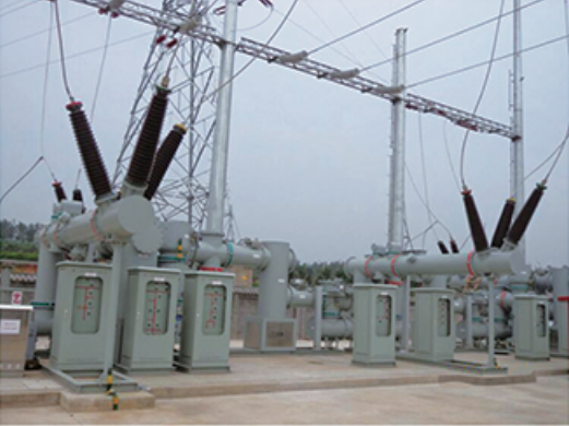
What Is Voltage Transformation, and Why Is It Important in Power Systems?
![]()
Voltage transformation is a fundamental process in power systems that enables the efficient transmission and distribution of electricity across vast distances. By stepping voltage up or down, transformers help minimize power losses, optimize grid performance, and ensure safe delivery of electricity to homes, businesses, and industries.
Voltage transformation is the process of converting electrical voltage levels using transformers to enable efficient power transmission and distribution. It is essential for minimizing energy losses, maintaining grid stability, and ensuring safe power delivery to end users.
This guide explores how voltage transformation works, its role in power systems, and why it is crucial for modern electrical infrastructure.
Voltage transformation is not necessary in modern power systems.False
Voltage transformation is essential for efficient electricity transmission and distribution, reducing energy losses and ensuring safe power delivery.
1. What Is Voltage Transformation?
A. Definition and Purpose
Voltage transformation is the conversion of electrical voltage levels using transformers to enable efficient energy transmission, distribution, and utilization.
✔ Step-Up Transformation: Increases voltage for long-distance transmission.
✔ Step-Down Transformation: Decreases voltage for safe end-user consumption.
✅ Voltage transformation ensures electricity travels efficiently while maintaining safety and reliability.
B. How Transformers Enable Voltage Transformation
Transformers operate based on Faraday’s Law of Electromagnetic Induction, which states that a changing magnetic field induces voltage in a nearby coil.
✔ Primary Winding: Receives input voltage.
✔ Laminated Core: Creates a magnetic field for energy transfer.
✔ Secondary Winding: Delivers transformed voltage output.
Voltage Transformation Formula
[\frac{V_s}{V_p} = \frac{N_s}{N_p}]
Where:
🔹 V_s / V_p = Voltage ratio between secondary and primary windings
🔹 N_s / N_p = Number of turns in the secondary and primary windings
✅ By adjusting the number of turns in the windings, transformers efficiently control voltage levels.
2. Why Is Voltage Transformation Important in Power Systems?
Voltage transformation is critical for efficient power generation, transmission, and distribution.
A. Minimizing Energy Losses in Transmission
| Transmission Factor | Low Voltage (No Transformation) | High Voltage (With Transformation) |
|---|---|---|
| Current Flow | High | Low |
| Resistive Losses (I²R) | High | Low |
| Efficiency | Poor | High |
✔ Higher voltage reduces current flow, minimizing resistive power losses.
✔ Long-distance transmission would be inefficient without step-up transformers.
✅ Voltage transformation enables cost-effective, long-distance power delivery.
B. Safe and Reliable Power Distribution
✔ High voltage is unsafe for residential and commercial use.
✔ Step-down transformers reduce voltage to safe levels (e.g., 120V, 230V).
✔ Stable voltage regulation prevents equipment damage and electrical hazards.
✅ Voltage transformation ensures reliable electricity for homes, industries, and businesses.
C. Enabling Renewable Energy Integration
✔ Wind and solar farms generate variable voltage levels.
✔ Transformers balance voltage fluctuations for stable grid integration.
✔ Energy storage systems require precise voltage control for efficiency.
✅ Voltage transformation supports the transition to renewable energy grids.
3. Types of Voltage Transformation in Power Systems
A. Step-Up and Step-Down Voltage Transformation
| Transformation Type | Purpose | Voltage Change | Example Application |
|---|---|---|---|
| Step-Up Transformer | Increases voltage | 13kV → 400kV | Power transmission from generators |
| Step-Down Transformer | Decreases voltage | 400kV → 11kV | Regional distribution substations |
✅ Step-up and step-down transformations optimize grid efficiency and safety.
B. Three-Phase vs. Single-Phase Transformers
✔ Three-Phase Transformers: Used in high-power transmission and industrial applications.
✔ Single-Phase Transformers: Used in residential power supply and small-scale electronics.
✅ Choosing the right transformer type improves power system performance.
C. Auto-Transformers for Efficient Voltage Adjustment
✔ Auto-transformers share primary and secondary windings, improving efficiency.
✔ Used for voltage regulation in power grids.
✔ Compact design reduces material and installation costs.
✅ Auto-transformers enhance efficiency in medium and high-voltage applications.
4. Future Trends in Voltage Transformation Technology
🚀 Smart Transformers: AI-driven real-time voltage optimization.
🚀 Solid-State Transformers (SSTs): High-frequency power conversion with increased efficiency.
🚀 Superconducting Transformers: Near-zero energy loss for ultra-efficient voltage transformation.
🚀 IoT-Enabled Monitoring: Digital control for predictive maintenance and grid stability.
💡 Next-generation voltage transformation technology will further improve efficiency and sustainability.
How Does Electromagnetic Induction Enable Voltage Transformation?
Voltage transformation is a fundamental process in electrical power systems, allowing efficient energy transmission and distribution. This process is made possible by electromagnetic induction, which enables transformers to increase or decrease voltage levels without direct electrical contact.
Electromagnetic induction enables voltage transformation by generating a changing magnetic field in a transformer’s core, which induces voltage in a secondary winding. This follows Faraday’s Law of Induction, allowing efficient energy transfer between circuits.
This guide explores how electromagnetic induction works in voltage transformation, its importance in power systems, and the key principles governing transformer operation.
Voltage transformation in transformers occurs through direct electrical connection between windings.False
Voltage transformation in transformers occurs through electromagnetic induction, where a changing magnetic field induces voltage in a secondary winding without direct electrical contact.
1. What Is Electromagnetic Induction?
A. Definition and Principles
Electromagnetic induction is the process by which a changing magnetic field generates an electric current in a conductor. It follows Faraday’s Law of Induction, which states:
💡 The induced voltage (EMF) in a coil is proportional to the rate of change of magnetic flux through the coil.
Mathematical Formula:
[EMF = -N \frac{d\Phi}{dt}]
Where:
🔹 EMF = Induced voltage (volts)
🔹 N = Number of turns in the coil
🔹 dΦ/dt = Rate of change of magnetic flux (Weber per second)
✅ Electromagnetic induction is the key mechanism behind how transformers modify voltage levels.
2. How Does Electromagnetic Induction Work in a Transformer?
A transformer consists of:
🔹 Primary Winding: The coil connected to the input AC voltage source.
🔹 Laminated Steel Core: Provides a magnetic pathway for energy transfer.
🔹 Secondary Winding: The coil where the induced voltage is generated.
A. Step-by-Step Process of Voltage Transformation
1️⃣ AC Voltage Applied to Primary Coil → Creates a changing magnetic field.
2️⃣ Magnetic Flux Circulates in the Core → Magnetic lines of force link both windings.
3️⃣ Induced EMF in the Secondary Coil → Voltage is generated based on the turns ratio.
4️⃣ Power Transfer Without Direct Contact → The magnetic field bridges the energy transfer.
✅ This process enables safe and efficient voltage conversion in electrical power systems.
3. The Role of Transformer Windings in Voltage Transformation
A. How Winding Turns Affect Voltage Output
The voltage transformation ratio depends on the number of turns in the primary and secondary windings:
[\frac{V_s}{V_p} = \frac{N_s}{N_p}]
Where:
🔹 V_s / V_p = Voltage ratio between secondary and primary windings
🔹 N_s / N_p = Turns ratio between secondary and primary coils
| Transformer Type | Turns Ratio | Voltage Effect |
|---|---|---|
| Step-Up Transformer | Ns > Np | Increases voltage |
| Step-Down Transformer | Ns < Np | Decreases voltage |
✅ Adjusting the number of coil turns determines whether the transformer steps voltage up or down.
4. Why Is Electromagnetic Induction Essential for Voltage Transformation?
A. Enables Efficient Power Transmission
✔ Reduces energy losses by optimizing voltage for transmission.
✔ Allows electricity to travel long distances without excessive heat dissipation.
✔ Improves stability and efficiency in power grids.
B. Provides Safe Voltage Conversion
✔ Allows high-voltage transmission and safe low-voltage usage.
✔ Prevents electrical hazards by isolating circuits.
✔ Supports precise voltage regulation for different applications.
✅ Electromagnetic induction ensures seamless voltage control in power systems.
5. Key Factors Affecting Voltage Transformation Efficiency
| Factor | Effect on Transformer Performance | Solution |
|---|---|---|
| Core Material | Impacts magnetic flux transfer | Use low-loss silicon steel or amorphous metal cores |
| Winding Resistance | Higher resistance increases energy loss | Use high-conductivity copper windings |
| Leakage Flux | Uncoupled flux reduces efficiency | Optimize winding placement to minimize leakage |
| Hysteresis & Eddy Currents | Core losses reduce overall efficiency | Use laminated cores and low-loss materials |
✅ Optimizing transformer design minimizes energy losses and improves performance.
6. Applications of Voltage Transformation in Power Systems
✔ Power Transmission: Steps voltage up for long-distance transmission and down for distribution.
✔ Industrial Equipment: Provides specific voltage levels for heavy machinery.
✔ Renewable Energy Systems: Integrates solar and wind power into the grid.
✔ Electric Vehicles (EVs): Regulates charging voltages for battery efficiency.
✅ Electromagnetic induction enables precise voltage control across diverse applications.
7. Future Innovations in Electromagnetic Induction for Transformers
🚀 Superconducting Transformers: Near-zero resistance for ultra-high efficiency.
🚀 Solid-State Transformers (SSTs): Advanced power electronics for better voltage control.
🚀 AI-Optimized Induction Systems: Real-time efficiency adjustments using machine learning.
🚀 Wireless Power Transfer: Electromagnetic induction for contactless energy transfer.
💡 Next-generation transformers will further enhance voltage transformation efficiency.
What Is the Difference Between Step-Up and Step-Down Transformers?

Transformers are essential for power transmission and distribution, allowing voltage levels to be efficiently adjusted for different applications. Step-up and step-down transformers serve opposite functions—one increases voltage for transmission, while the other reduces voltage for safe usage. Understanding their differences is crucial for designing efficient electrical systems.
A step-up transformer increases voltage while decreasing current, making power transmission more efficient. A step-down transformer decreases voltage for safe distribution and usage in homes, industries, and electronic devices. Both rely on electromagnetic induction to transfer energy between circuits.
This guide explores the key differences between step-up and step-down transformers, their working principles, applications, and advantages in power systems.
Step-up and step-down transformers operate in the same way without differences in function.False
Step-up transformers increase voltage for transmission, while step-down transformers decrease voltage for distribution and safe use. Both serve distinct purposes in power systems.
1. Key Differences Between Step-Up and Step-Down Transformers
| Feature | Step-Up Transformer | Step-Down Transformer |
|---|---|---|
| Function | Increases voltage, reduces current | Decreases voltage, increases current |
| Primary Winding | Fewer turns | More turns |
| Secondary Winding | More turns | Fewer turns |
| Voltage Conversion | Low to high voltage | High to low voltage |
| Current Behavior | Output current decreases | Output current increases |
| Primary Use | Power transmission over long distances | Power distribution for consumer use |
| Applications | Power plants, renewable energy transmission | Homes, industries, electronic devices |
✅ Step-up transformers enable efficient energy transmission, while step-down transformers ensure safe electricity use.
2. How Do Step-Up and Step-Down Transformers Work?
Both step-up and step-down transformers operate using electromagnetic induction, following Faraday’s Law of Induction:
✔ A changing magnetic field in the transformer’s core induces voltage in the secondary winding.
✔ The voltage ratio depends on the number of turns in the primary and secondary coils.
Voltage Transformation Formula
[\frac{V_s}{V_p} = \frac{N_s}{N_p}]
Where:
🔹 V_s / V_p = Voltage ratio between secondary and primary windings
🔹 N_s / N_p = Turns ratio between secondary and primary coils
✅ By adjusting the number of coil turns, transformers efficiently step voltage up or down.
A. Step-Up Transformer: Increasing Voltage for Transmission
🔹 Fewer primary winding turns, more secondary winding turns.
🔹 Voltage increases, current decreases to minimize resistive power losses.
🔹 Used in power plants, wind and solar farms, and high-voltage transmission lines.
Example:
🔹 Power plant output: 11kV
🔹 Transmission voltage after step-up: 400kV (for long-distance power transmission)
✅ Step-up transformers reduce transmission losses and improve grid efficiency.
B. Step-Down Transformer: Decreasing Voltage for Safe Use
🔹 More primary winding turns, fewer secondary winding turns.
🔹 Voltage decreases, current increases to meet power demands safely.
🔹 Used in distribution substations, industrial machines, and household appliances.
Example:
🔹 Transmission voltage: 400kV
🔹 Distribution voltage after step-down: 11kV → 230V (for residential and industrial use)
✅ Step-down transformers ensure safe electricity use in homes and businesses.
3. Applications of Step-Up and Step-Down Transformers
| Application | Step-Up Transformer | Step-Down Transformer |
|---|---|---|
| Power Plants | Converts generated power to high voltage for transmission | - |
| Electric Grid Transmission | Raises voltage to reduce energy losses | - |
| Industrial Power Distribution | - | Reduces voltage for machinery and equipment |
| Renewable Energy Systems | Steps up voltage from solar/wind farms to connect to the grid | - |
| Electric Vehicles (EVs) | Steps up battery voltage for high-power applications | Steps down voltage for charging stations |
| Household Power Supply | - | Converts high-voltage supply to safe levels for homes |
| Electronics and Appliances | - | Steps down voltage for devices like TVs, chargers, and laptops |
✅ Transformers enable efficient and safe power distribution across various industries.
4. Efficiency Considerations in Step-Up and Step-Down Transformers
✔ Minimizing Core and Copper Losses:
🔹 High-permeability core materials (silicon steel, amorphous metal) reduce losses.
🔹 High-conductivity copper windings improve energy transfer efficiency.
✔ Optimizing Cooling Systems:
🔹 Oil-immersed transformers for high-power applications.
🔹 Dry-type transformers for indoor and low-power applications.
✅ Modern transformer designs enhance efficiency, reducing energy waste and operational costs.
5. Future Innovations in Voltage Transformation
🚀 Smart Transformers: AI-driven voltage optimization for dynamic grid management.
🚀 Solid-State Transformers (SSTs): Power electronics-based solutions for more precise voltage control.
🚀 Superconducting Transformers: Near-zero resistance for ultra-high efficiency.
🚀 Wireless Power Transfer: Electromagnetic induction without physical windings for step-up/down conversion.
💡 Future transformers will be more efficient, compact, and adaptable to smart grids.
How Do Primary and Secondary Windings Determine Voltage Levels?
Transformers play a crucial role in power transmission and distribution, converting voltage levels to ensure efficient energy transfer. The number of turns in the primary and secondary windings determines the output voltage, allowing transformers to step voltage up or down based on application needs.
Primary and secondary windings determine voltage levels based on the turns ratio. The voltage transformation follows Faraday’s Law of Induction, where the ratio of the number of turns in the windings dictates whether the voltage is increased (step-up transformer) or decreased (step-down transformer).
This guide explores how winding design affects voltage transformation, the mathematical principles behind it, and practical applications in power systems.
The voltage levels in a transformer are independent of the number of turns in the windings.False
The voltage transformation in a transformer depends on the ratio of the number of turns in the primary and secondary windings, following Faraday’s Law of Induction.
1. How Do Primary and Secondary Windings Work in a Transformer?
A. Structure of Transformer Windings
A transformer consists of:
🔹 Primary Winding – Receives AC voltage input.
🔹 Laminated Core – Provides a magnetic pathway for energy transfer.
🔹 Secondary Winding – Delivers transformed voltage output.
✔ AC voltage applied to the primary winding generates a changing magnetic field.
✔ The magnetic flux induces voltage in the secondary winding, following electromagnetic induction principles.
✔ The voltage ratio depends on the number of turns in each winding.
✅ The windings interact through the core, enabling efficient voltage transformation.
B. The Turns Ratio and Voltage Transformation
The voltage transformation ratio is determined by the turns ratio between the primary and secondary windings:
Voltage Transformation Formula
[\frac{V_s}{V_p} = \frac{N_s}{N_p}]
Where:
🔹 V_s = Secondary voltage
🔹 V_p = Primary voltage
🔹 N_s = Number of secondary winding turns
🔹 N_p = Number of primary winding turns
✔ If (N_s > N_p) → The transformer is a step-up transformer (increases voltage).
✔ If (N_s < N_p) → The transformer is a step-down transformer (decreases voltage).
✅ By adjusting the number of turns in the windings, transformers precisely control voltage levels.
2. How Windings Affect Step-Up and Step-Down Transformers
A. Step-Up Transformer: Increasing Voltage for Transmission
✔ More turns in the secondary winding than in the primary winding ((N_s > N_p)).
✔ Output voltage is higher than input voltage.
✔ Used in power plants and renewable energy systems to step up voltage for transmission.
Example:
🔹 Primary Voltage ((V_p)) = 11kV
🔹 Secondary Voltage ((V_s)) = 400kV
🔹 Turns Ratio ((\frac{N_s}{N_p})) = 36.4
✅ Step-up transformers enable efficient long-distance electricity transmission.
B. Step-Down Transformer: Reducing Voltage for Safe Use
✔ More turns in the primary winding than in the secondary winding ((N_p > N_s)).
✔ Output voltage is lower than input voltage.
✔ Used in substations, homes, and industrial equipment to ensure safe power delivery.
Example:
🔹 Primary Voltage ((V_p)) = 400kV
🔹 Secondary Voltage ((V_s)) = 230V
🔹 Turns Ratio ((\frac{N_s}{N_p})) = 0.0006
✅ Step-down transformers provide safe and usable voltage for consumers.
3. The Role of Windings in Current and Power Transfer
While voltage is transformed, power remains constant (neglecting losses):
Power Equation:
[Pp = Ps]
[Vp Ip = Vs Is]
Where:
🔹 Pp· Ps = Power in the primary and secondary windings
🔹 Ip· Is = Current in the primary and secondary windings
✔ If voltage increases (step-up), current decreases.
✔ If voltage decreases (step-down), current increases.
✅ Transformers maintain power balance while adjusting voltage and current as needed.
4. Practical Applications of Voltage Transformation
| Application | Step-Up Transformer | Step-Down Transformer |
|---|---|---|
| Power Transmission | Increases voltage to reduce transmission losses | - |
| Substation Distribution | - | Reduces voltage for local grids |
| Renewable Energy Systems | Steps up voltage from solar/wind farms | - |
| Electric Vehicles (EVs) | Boosts battery voltage for high-power applications | Regulates voltage for charging stations |
| Household Appliances | - | Converts voltage to safe levels for home use |
✅ Windings play a critical role in voltage regulation across multiple industries.
5. Future Innovations in Transformer Winding Technology
🚀 Superconducting Windings: Near-zero electrical resistance for ultra-high efficiency.
🚀 Graphene-Based Conductors: Lighter, stronger, and more conductive than copper.
🚀 AI-Optimized Winding Designs: Predictive models to reduce losses and improve performance.
🚀 3D-Printed Transformer Coils: Enhanced precision and material efficiency.
💡 Advanced winding technology will further improve voltage transformation efficiency.
What Factors Affect the Efficiency of Voltage Transformation?

Voltage transformation is a critical function of transformers, allowing efficient power transmission and distribution. However, various factors affect the efficiency of voltage transformation, leading to energy losses in the form of heat, electromagnetic interference, and resistive losses. Optimizing these factors is essential to reduce energy waste, lower operational costs, and improve transformer performance.
The efficiency of voltage transformation is affected by core losses, copper losses, winding design, load conditions, cooling systems, and material selection. Reducing these losses enhances energy efficiency, improves power transmission, and extends transformer lifespan.
This guide explores the key factors influencing transformer efficiency, how they impact performance, and best practices to minimize energy losses.
Transformer efficiency is unaffected by design and material selection.False
Transformer efficiency depends on core materials, winding design, cooling methods, and loss reduction techniques, which optimize performance and reduce energy waste.
1. Key Factors Affecting Voltage Transformation Efficiency
A. Core Losses (No-Load Losses)
Core losses occur due to magnetic properties of the core material and persist even when no load is connected.
| Core Loss Type | Cause | Effect on Efficiency |
|---|---|---|
| Hysteresis Loss | Magnetic domain realignment in the core | Increases heat generation, reduces efficiency |
| Eddy Current Loss | Induced circulating currents within the core | Wastes electrical energy, leads to overheating |
How to Minimize Core Losses
✔ Use High-Permeability Core Materials – Amorphous metal and silicon steel reduce hysteresis losses.
✔ Laminated Core Design – Thin insulated steel sheets limit eddy current formation.
✔ Optimize Flux Density – Prevent excessive magnetic saturation.
✅ Lower core losses improve transformer efficiency, especially during no-load conditions.
B. Copper Losses (Load Losses)
Copper losses arise due to the resistance of transformer windings. These losses increase with load current.
| Copper Loss Type | Cause | Impact on Efficiency |
|---|---|---|
| I²R Loss | Electrical resistance in windings | Generates heat, reduces output power |
| Stray Losses | Leakage flux inducing currents in non-winding components | Causes additional heating, lowers efficiency |
How to Minimize Copper Losses
✔ Use Low-Resistance Winding Materials – High-conductivity copper or superconductors reduce losses.
✔ Increase Conductor Thickness – Reduces electrical resistance.
✔ Improve Winding Geometry – Proper winding placement minimizes leakage flux.
✅ Reducing copper losses ensures efficient voltage conversion under load conditions.
C. Winding Configuration and Electromagnetic Coupling
Proper winding design improves voltage transformation by ensuring strong electromagnetic coupling between primary and secondary windings.
✔ Higher Winding Turns Ratio – Provides precise voltage control.
✔ Tightly Coupled Windings – Reduces energy losses due to stray magnetic flux.
✔ Optimized Coil Shape (Helical, Disc, or Pancake Windings) – Improves electromagnetic efficiency.
✅ Efficient winding configurations enhance transformer performance and voltage accuracy.
D. Load Conditions and Transformer Sizing
Voltage transformation efficiency is highest at or near full load. Overloading or underloading affects performance.
| Load Condition | Effect on Efficiency |
|---|---|
| Underloading (Below 50%) | Core losses become dominant, reducing efficiency |
| Optimal Loading (70-100%) | Best efficiency range, balanced core and copper losses |
| Overloading (Above 100%) | High copper losses, excessive heat, insulation degradation |
How to Optimize Load Conditions
✔ Use Properly Sized Transformers – Avoid underloading or overloading.
✔ Monitor Load Fluctuations – Real-time load tracking prevents inefficiencies.
✔ Balance Power Distribution – Evenly distribute loads to optimize efficiency.
✅ Maintaining optimal load conditions reduces energy waste and extends transformer lifespan.
E. Cooling System Efficiency and Thermal Management
Overheating decreases efficiency by increasing resistance and accelerating insulation breakdown. Efficient cooling reduces energy losses.
| Cooling Method | Heat Dissipation Efficiency | Best Application |
|---|---|---|
| ONAN (Oil Natural Air Natural) | ⭐⭐⭐ Moderate | Small transformers |
| ONAF (Oil Natural Air Forced) | ⭐⭐⭐⭐ High | Medium transformers |
| OFWF (Oil Forced Water Forced) | ⭐⭐⭐⭐⭐ Very High | Large industrial transformers |
| Dielectric Liquid Cooling | ⭐⭐⭐⭐⭐ Ultra High | High-voltage applications |
How to Improve Cooling Efficiency
✔ Use AI-Controlled Cooling Systems – Adjusts fan and oil circulation dynamically.
✔ Maintain Optimal Oil Levels and Quality – Prevents thermal degradation.
✔ Apply Phase-Change Cooling Materials – Enhances heat absorption and dissipation.
✅ Better cooling maintains stable voltage transformation and prevents energy losses.
F. Insulation and Dielectric Losses
Dielectric losses occur in transformer insulation materials, reducing efficiency and increasing heat buildup.
| Factor | Impact | Solution |
|---|---|---|
| Insulation Aging | Higher dielectric losses, reduced efficiency | Regular insulation testing and maintenance |
| Moisture Contamination | Lowers insulation strength, increases losses | Use moisture-resistant dielectric fluids |
| Poor Oil Quality | Reduces cooling and insulation properties | Use high-performance biodegradable oils |
✅ Using high-quality insulation materials minimizes dielectric losses, improving transformer longevity.
2. How to Improve Overall Transformer Efficiency
✔ Use High-Efficiency Core Materials – Amorphous metals and nanocrystalline alloys reduce energy losses.
✔ Implement Smart Load Management – AI-driven systems adjust voltage dynamically.
✔ Upgrade Cooling Systems – Smart cooling enhances thermal efficiency.
✔ Monitor and Maintain Oil Quality – Regular testing prevents overheating and degradation.
✔ Adopt Predictive Maintenance Strategies – AI-based monitoring detects inefficiencies early.
✅ Combining these strategies maximizes voltage transformation efficiency, reducing operational costs.
3. Future Innovations in Transformer Efficiency
🚀 Superconducting Windings: Near-zero resistance for minimal copper losses.
🚀 AI-Driven Predictive Maintenance: Real-time fault detection for optimized performance.
🚀 Self-Healing Insulation Materials: Automatically repair minor faults, extending lifespan.
🚀 Solid-State Transformers (SSTs): Power electronics-based systems for ultra-efficient voltage conversion.
💡 Next-generation transformers will achieve near-perfect efficiency, reducing energy waste and improving sustainability.
How Can Voltage Transformation Be Optimized for Power Grid Stability?
Voltage transformation plays a critical role in ensuring power grid stability, allowing electricity to be transmitted efficiently over long distances and delivered safely to consumers. Optimizing voltage transformation minimizes energy losses, prevents grid fluctuations, and enhances system reliability. By integrating smart transformers, AI-driven load management, and advanced voltage regulation techniques, modern power grids can become more stable, efficient, and resilient.
Voltage transformation can be optimized for power grid stability by using smart transformers, dynamic voltage regulation, real-time grid monitoring, and load balancing. These techniques help prevent voltage fluctuations, minimize losses, and improve overall grid reliability.
This guide explores how voltage transformation affects grid stability, key optimization techniques, and future trends in power system management.
Voltage transformation does not impact power grid stability.False
Voltage transformation directly affects grid stability by ensuring proper voltage levels for transmission, distribution, and end-user consumption, minimizing power fluctuations.
1. Why Is Voltage Transformation Critical for Grid Stability?
A. The Role of Voltage Transformation in Power Grids
✔ Increases Voltage for Long-Distance Transmission → Reduces energy losses and improves efficiency.
✔ Decreases Voltage for Safe Distribution → Ensures end-user safety and equipment protection.
✔ Balances Load and Voltage Levels → Prevents overloads and power quality issues.
B. Consequences of Poor Voltage Transformation
| Issue | Cause | Effect on Grid Stability |
|---|---|---|
| Voltage Fluctuations | Unstable transformation ratios | Equipment damage, system blackouts |
| Transmission Losses | Inefficient step-up/step-down processes | Higher operational costs |
| Power Quality Issues | Poor load balancing | Harmonics, frequency instability |
| Overloading & Voltage Collapse | Incorrect transformer sizing | Grid failure, cascading outages |
✅ Optimized voltage transformation ensures reliable electricity delivery with minimal disruptions.
2. Techniques to Optimize Voltage Transformation for Grid Stability
A. Smart Transformers for Real-Time Voltage Adjustment
✔ AI-Controlled Voltage Regulation: Automatically adjusts voltage based on demand.
✔ Self-Healing Systems: Detects and isolates faults to prevent instability.
✔ IoT-Enabled Monitoring: Real-time data collection for predictive maintenance.
✅ Smart transformers improve grid adaptability and reduce system failures.
B. Dynamic Load Balancing and Voltage Optimization
✔ Automatic Voltage Regulators (AVRs): Adjust transformer output to match grid conditions.
✔ Flexible AC Transmission Systems (FACTS): Enhances voltage stability during load variations.
✔ Real-Time Load Shifting: Distributes power based on consumption patterns.
✅ Dynamic voltage optimization prevents sudden drops or surges, improving reliability.
C. Advanced Grid Monitoring and Control Systems
| Technology | Function | Benefit to Grid Stability |
|---|---|---|
| SCADA (Supervisory Control and Data Acquisition) | Real-time monitoring of transformers and substations | Quick fault detection and response |
| PMUs (Phasor Measurement Units) | Tracks voltage phase angles across the grid | Prevents cascading failures |
| AI-Based Predictive Analytics | Analyzes transformer performance data | Prevents voltage fluctuations before they occur |
✅ Advanced monitoring systems allow grid operators to maintain precise voltage control.
D. High-Efficiency Transformer Materials and Design
✔ Amorphous Metal Cores: Reduce core losses for better voltage stability.
✔ Superconducting Transformers: Eliminate resistive losses for ultra-efficient transformation.
✔ High-Performance Cooling Systems: Maintain optimal transformer temperature to prevent efficiency drops.
✅ Using cutting-edge transformer materials improves voltage stability and reduces energy waste.
3. Case Studies: Real-World Applications of Optimized Voltage Transformation
A. Smart Transformer Deployment in Urban Grids
📌 City: New York, USA
📌 Challenge: Voltage instability due to fluctuating demand.
📌 Solution: AI-driven transformers with self-regulating voltage control.
📌 Result: 30% reduction in voltage fluctuations, improved grid resilience.
B. FACTS Technology for Renewable Energy Integration
📌 Location: Germany
📌 Challenge: Unstable voltage levels due to solar and wind power fluctuations.
📌 Solution: FACTS devices to dynamically regulate grid voltage.
📌 Result: Improved voltage stability and seamless integration of 50% renewable energy.
✅ Implementing smart voltage transformation techniques enhances grid performance worldwide.
4. Future Trends in Voltage Transformation for Power Grid Stability
🚀 AI-Based Grid Autonomy: Self-learning algorithms for voltage optimization.
🚀 Decentralized Smart Grids: Microgrid integration for localized voltage control.
🚀 Solid-State Transformers (SSTs): High-frequency power conversion with ultra-fast voltage regulation.
🚀 Wireless Power Transfer: Contactless voltage transformation for improved efficiency.
💡 Next-generation voltage transformation technologies will make power grids more resilient, efficient, and sustainable.
Conclusion
Voltage transformation in power transformers plays a crucial role in efficient energy transmission and distribution. By leveraging electromagnetic induction, these devices adjust voltage levels to meet system requirements, minimize losses, and ensure stable power supply. Understanding the working principles and efficiency factors helps in optimizing transformer performance and reliability.
Need expert guidance on power transformer selection and optimization? Contact us today for professional support!
FAQ
What is voltage transformation in power transformers?
Voltage transformation refers to the process of increasing or decreasing electrical voltage in power transformers using electromagnetic induction to transfer energy efficiently.
How does a power transformer change voltage?
A power transformer changes voltage by using primary and secondary windings wrapped around a magnetic core. The turns ratio between these windings determines whether the voltage is stepped up or down.
What is the difference between step-up and step-down transformers?
A step-up transformer increases voltage from the primary to the secondary winding, while a step-down transformer reduces voltage, making it suitable for safer distribution.
Why is voltage transformation important in power transmission?
Voltage transformation reduces power losses during long-distance transmission, improves efficiency, and ensures proper voltage levels for industrial and residential applications.
What factors affect the efficiency of voltage transformation?
Efficiency depends on core material, winding resistance, transformer cooling, and the minimization of eddy current and hysteresis losses in the transformer core.
References
- How Transformers Work - https://www.electronics-tutorials.ws
- Basics of Voltage Transformation - https://www.khanacademy.org
- Step-Up vs. Step-Down Transformers - https://www.electrical4u.com
- Power Transmission & Efficiency - https://www.energy.gov
- Transformer Design and Loss Reduction - https://www.sciencedirect.com
- Role of Magnetic Cores in Transformers - https://www.researchgate.net
- Transformer Cooling Techniques - https://www.nfpa.org
- High Voltage Power Distribution - https://www.ieee.org
- Voltage Control in Electrical Grids - https://www.epa.gov
- Smart Transformers in Modern Grids - https://www.mdpi.com
