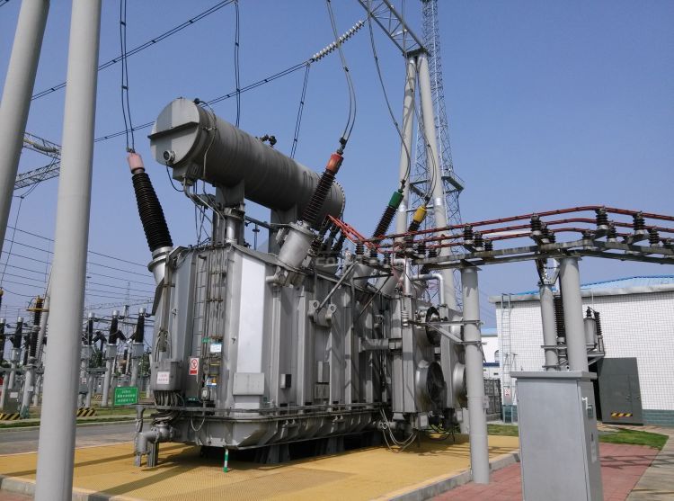
A power transformer is a complex electrical device designed to change voltage levels in an alternating current (AC) system. It plays a crucial role in the power grid by enabling the efficient transmission and distribution of electricity across long distances. Understanding the internal structure of a power transformer is essential for recognizing how it functions, how its components work together, and how it contributes to the overall efficiency and stability of the electrical system. This article will explore the key internal elements of a power transformer, their specific roles, and how the transformer operates to regulate voltage levels.
What is the Basic Internal Structure of a Power Transformer?
Power transformers are essential components in electrical power systems, as they are responsible for transforming voltage levels to ensure the efficient transmission and distribution of electricity. Understanding the basic internal structure of a power transformer is crucial for engineers, technicians, and anyone involved in the design, maintenance, or operation of electrical systems. It’s important to know how a power transformer works, as it directly impacts the efficiency, safety, and reliability of electrical infrastructure. In this article, we’ll dive into the basic internal structure of a power transformer and how each component contributes to its overall function.
A power transformer typically consists of several key internal components that work together to transfer electrical energy between circuits. These components include the transformer core, windings, tap changer, bushings, tank, and insulation system. Each part plays a critical role in ensuring the transformer operates effectively, efficiently, and safely.
The basic internal structure of a power transformer includes the transformer core, primary and secondary windings, bushings, tap changer, tank, and insulation system. The core is made from laminated sheets of silicon steel, which provide low core loss and high permeability. The windings are made from copper or aluminum and are wound around the core, with primary windings receiving input voltage and secondary windings delivering output voltage.
The transformer’s core is the heart of the device, as it channels the magnetic field generated by the electrical current. The windings are essential for creating the electrical magnetic field that transforms the voltage levels. The bushings, tap changer, and insulation ensure the safe operation of the transformer, preventing electrical faults and enhancing performance. Let’s take a closer look at each of these components.
1. Transformer Core
The transformer core is the primary component that facilitates the transfer of electrical energy between the primary and secondary windings. It is typically made of laminated sheets of silicon steel, which help reduce energy loss due to eddy currents. The core is designed to be highly permeable, meaning it can efficiently conduct magnetic flux.
The core's main function is to concentrate the magnetic flux generated by the electrical current passing through the windings. This concentrated flux induces a voltage in the secondary winding, allowing the voltage to be stepped up or stepped down. The core is usually in a closed loop shape, such as a "C-core" or "E-core," to provide a continuous path for the magnetic flux.
2. Primary and Secondary Windings
The windings in a transformer are copper or aluminum coils wound around the transformer’s core. There are typically two sets of windings: the primary winding and the secondary winding.
- Primary Winding: The primary winding is connected to the input voltage source. It generates a magnetic field when electric current flows through it, which induces a voltage in the secondary winding.
- Secondary Winding: The secondary winding is where the transformed voltage is delivered. The voltage induced in this winding can either be higher or lower than the primary voltage, depending on the transformer’s design (step-up or step-down transformer).
The ratio of turns between the primary and secondary windings determines the voltage transformation. If the secondary winding has more turns than the primary, the transformer is a step-up transformer. If the secondary winding has fewer turns, the transformer is a step-down transformer.
| Winding Type | Connection | Function |
|---|---|---|
| Primary Winding | Connected to input voltage | Generates magnetic field to induce voltage in secondary winding |
| Secondary Winding | Connected to output load | Receives induced voltage and delivers transformed voltage to the load |
3. Tap Changer
A tap changer is a device that allows the voltage to be adjusted within certain limits. It is often used in transformers where the output voltage needs to be fine-tuned or adjusted for varying load conditions. Tap changers are typically used in step-down transformers, and they provide additional control over voltage regulation.
Tap changers work by selecting different “taps” on the winding to change the turns ratio, thus adjusting the output voltage. There are two main types of tap changers:
- On-load Tap Changer (OLTC): These can change taps while the transformer is under load, offering dynamic voltage regulation.
- Off-load Tap Changer: These must be adjusted when the transformer is not under load, typically used for maintenance or static adjustments.
4. Bushings
Bushings are the components through which the electrical current enters and exits the transformer. They are typically made from insulating materials such as porcelain or composite materials to ensure that electrical conductors are safely separated from the transformer tank. Bushings are mounted on the top or side of the transformer, and they provide the path for the connection of the primary and secondary windings to external electrical systems.
The bushings must have high dielectric strength to withstand high voltages and prevent electrical flashover. Insulating oil or other insulating materials are often used around the bushings to provide additional safety and improve performance.
5. Transformer Tank
The transformer tank is a metallic casing that surrounds the internal components of the transformer. It provides structural support and serves as a container for the insulating oil or other cooling mediums. The tank protects the internal components from external environmental factors such as moisture, dust, and physical damage.
In addition to its protective role, the transformer tank also plays a critical function in cooling. Transformers generate heat as they operate, and the oil inside the tank helps dissipate this heat, keeping the transformer at an optimal temperature for safe and efficient operation.
6. Insulation System
The insulation system in a power transformer plays a crucial role in ensuring safe and efficient operation. It prevents electrical short circuits and breakdowns by isolating the windings and other components from each other and from the transformer tank. The insulation system usually consists of several layers:
- Solid Insulation: Often made from materials such as paper or rubber, solid insulation is used to separate the windings and prevent direct contact.
- Liquid Insulation: Transformer oil (or another insulating fluid) is used to provide additional insulation, help cool the transformer, and absorb any moisture that could affect performance.
- Gaseous Insulation: Some transformers use gas (such as sulfur hexafluoride) as an additional insulating medium, particularly in high-voltage transformers.
Summary Table of Transformer Components
| Component | Material | Function |
|---|---|---|
| Core | Silicon steel | Concentrates magnetic flux for voltage induction |
| Primary Winding | Copper or aluminum coils | Receives input voltage and generates magnetic field |
| Secondary Winding | Copper or aluminum coils | Delivers output voltage, transformed from input |
| Tap Changer | Mechanical/electrical device | Adjusts the voltage output by changing the winding taps |
| Bushings | Porcelain, composite | Provides electrical connections to the external system |
| Tank | Steel | Protects the transformer and houses the cooling oil |
| Insulation System | Paper, rubber, oil, gas | Prevents electrical short circuits and aids cooling |
ClaimReview fact check in the text.
The core of a transformer is made from laminated silicon steel to reduce energy loss.True
The silicon steel core reduces eddy current losses and increases the efficiency of the transformer.
How Does the Core of a Power Transformer Work?
The core of a power transformer plays a vital role in the transformer’s function, serving as the central component for the conversion of electrical energy between the primary and secondary windings. It is a crucial part of the transformer’s ability to efficiently transfer power and adjust voltage levels for a wide range of applications, from power transmission to household appliances. Without an effective transformer core, energy losses would be high, and transformers would not operate efficiently.
Understanding the operation of a power transformer’s core is essential for anyone working in electrical engineering, as it directly impacts the performance, safety, and efficiency of electrical systems. This article will explore the core's structure, its working principles, and how it contributes to the transformer’s overall efficiency.
The core of a power transformer works by channeling the magnetic flux generated by the current flowing through the windings. Made from laminated sheets of silicon steel, the core provides a low-resistance path for the magnetic field, which allows the transformer to efficiently induce voltage in the secondary winding. This process relies on electromagnetic induction to transfer electrical energy between the primary and secondary circuits.
The core’s efficiency is critical for minimizing energy losses, particularly those caused by eddy currents and hysteresis. A well-designed core reduces these losses, ensuring the transformer operates at optimal efficiency. In this article, we will break down the core’s structure, its key functions, and how it works in harmony with other transformer components.
Structure of a Power Transformer Core
The core of a power transformer is made from thin sheets of silicon steel that are stacked together. These sheets are laminated to reduce energy losses due to eddy currents, which can significantly reduce the transformer’s efficiency. The core’s design allows it to focus the magnetic flux, directing it through the windings to induce the desired voltage transformation.
Key components of the core structure include:
Laminated Sheets of Silicon Steel: The core is made up of thin, laminated sheets of silicon steel, which are stacked together to form a closed-loop structure. Silicon steel is used due to its excellent magnetic properties, such as high permeability, which allows the core to effectively channel magnetic flux.
Core Shape: The core is typically built in a rectangular, “E-core” or "C-core" shape. These designs create a closed-loop magnetic path, allowing the magnetic flux to circulate efficiently between the primary and secondary windings.
Magnetic Path: The magnetic flux generated by the primary winding travels through the core, inducing a voltage in the secondary winding. The core provides a low-resistance path for this flux, ensuring that the magnetic field is effectively transmitted from one coil to the other.
Core Losses: As the transformer operates, the core experiences some energy losses, including eddy current losses and hysteresis losses. These losses are minimized by using laminated sheets, which help reduce eddy currents, and by selecting materials with low hysteresis, such as silicon steel.
How the Core Works in the Transformer
The transformer operates based on the principle of electromagnetic induction, where a magnetic field is created by the current flowing through the primary winding. This magnetic field passes through the transformer core, inducing a voltage in the secondary winding.
Here’s a simplified breakdown of how the core works:
Magnetic Field Generation (Primary Winding): When alternating current (AC) flows through the primary winding, it creates a time-varying magnetic field around the winding. This magnetic field expands and collapses with the AC cycle.
Magnetic Flux in the Core: The alternating magnetic field generated by the primary winding passes through the core. The silicon steel core channels the magnetic flux efficiently, reducing energy losses and guiding the magnetic field into the secondary winding.
Induced Voltage (Secondary Winding): As the magnetic flux passes through the secondary winding, it induces a voltage due to the principle of electromagnetic induction. The amount of voltage induced depends on the number of turns in the secondary winding relative to the primary winding, which determines whether the transformer is a step-up or step-down transformer.
Flux Linkage: The magnetic flux in the core links the primary and secondary windings. The flux is ideally contained within the core, which is why the core’s magnetic properties and design are so critical to the transformer's efficiency.
Core Losses and Efficiency
While the core plays a central role in transferring energy, it also experiences some energy losses. The two main types of losses that occur within the transformer core are eddy current losses and hysteresis losses.
Eddy Current Losses: These losses are caused by circulating currents that are induced in the conductive material of the core (typically silicon steel). These currents flow in closed loops and generate heat, reducing the efficiency of the transformer. Eddy currents are minimized by using laminated sheets of steel in the core, which restricts the flow of these currents.
Hysteresis Losses: When the magnetic material of the core is magnetized and demagnetized with the changing AC current, energy is lost due to the internal friction between the magnetic domains in the material. The energy required to reorient the magnetic domains contributes to hysteresis losses. The use of high-quality silicon steel reduces these losses by offering low hysteresis.
To minimize these losses and increase efficiency, transformer cores are carefully designed and manufactured with specific materials and structural features.
Core Design Variations
There are different core designs based on the application, voltage ratings, and power ratings of the transformer. The two most common core configurations are:
Closed-Core Transformers: In this design, the magnetic core forms a complete loop, meaning the magnetic flux flows continuously through the core. This design ensures high efficiency as there is minimal leakage of magnetic flux. Closed-core transformers are used in most industrial and power grid applications.
Shell-Core Transformers: In shell-core designs, the core surrounds the windings on all sides. This design minimizes flux leakage and reduces the overall size of the transformer. Shell-core transformers are often used in smaller transformers, such as those for household or commercial use.
| Core Design | Magnetic Flux Path | Advantages | Applications |
|---|---|---|---|
| Closed-Core | Magnetic flux forms a closed loop around the windings | High efficiency, minimal flux leakage | Industrial power transformers, power grids |
| Shell-Core | Core surrounds the windings on all sides | Reduced transformer size, lower flux leakage | Household appliances, small power transformers |
Material Considerations for Transformer Cores
The material used for the transformer core is critical to its performance. The most commonly used material is silicon steel, chosen for its excellent magnetic properties, such as high permeability and low hysteresis loss. However, there are also other materials, such as:
Amorphous Steel: This is a type of steel with a disordered atomic structure, offering even lower core losses compared to traditional silicon steel. It is becoming increasingly popular in energy-efficient transformers.
Ferrite Materials: Used primarily in small transformers or those designed for high-frequency applications, ferrites are ceramic materials that offer high magnetic permeability at high frequencies.
ClaimReview fact check in the text.
The core of a transformer is made from laminated silicon steel to reduce energy losses due to eddy currents.True
Laminating the core material reduces the flow of eddy currents, which in turn reduces energy losses and increases the transformer’s efficiency.
What Role Do the Windings Play in a Power Transformer?
Power transformers are essential components of electrical systems, responsible for stepping up or stepping down voltage levels to ensure the efficient transmission and distribution of electricity. While the core plays a critical role in guiding the magnetic flux, it is the windings in the transformer that directly manage the electrical energy, both in terms of input and output. The windings are fundamental to the transformer’s ability to perform the voltage transformation, and their design, placement, and construction affect the transformer’s efficiency, reliability, and safety.
In this article, we will delve into the essential role of the windings in a power transformer, explaining their function, how they work with the core, and how the design and configuration of the windings influence the transformer’s overall performance.
The windings of a power transformer serve as the primary and secondary electrical circuits, allowing electrical energy to be transferred between them via electromagnetic induction. The primary winding receives energy from the input power supply, creating a magnetic field that induces a voltage in the secondary winding, thereby transforming the voltage level.
To better understand the intricacies of transformer windings, let’s break down their structure, function, and impact on transformer efficiency.
Function of Windings in a Power Transformer
The windings of a power transformer are typically made of copper or aluminum wire, wrapped in coils around the transformer’s core. These windings are responsible for transmitting electrical energy between the primary and secondary circuits, relying on the principles of electromagnetic induction to transfer power. Here's a detailed look at how windings function:
Primary Winding (Input Side): The primary winding receives alternating current (AC) from the power source. When AC flows through this winding, it creates a time-varying magnetic field around the winding. This magnetic field is directed through the core and induces voltage in the secondary winding.
Secondary Winding (Output Side): The secondary winding is where the voltage transformation occurs. The induced voltage in this winding depends on the number of turns in the winding and the magnetic flux created by the primary winding. Depending on the turn ratio, the transformer steps up or steps down the voltage.
Key Point: The voltage induced in the secondary winding is directly proportional to the turns ratio between the primary and secondary windings. If the secondary winding has more turns than the primary, the transformer is a step-up transformer. Conversely, if the secondary winding has fewer turns than the primary, the transformer is a step-down transformer.
- Energy Transfer via Electromagnetic Induction: The process by which electrical energy is transferred from the primary winding to the secondary winding is based on electromagnetic induction. As the magnetic field fluctuates in the core due to the AC in the primary winding, it induces a voltage in the secondary winding without any physical connection between the two windings.
Key Characteristics of Transformer Windings
To optimize the performance of a transformer, the windings must be designed with specific characteristics that ensure efficient energy transfer, minimize losses, and provide durability over time. The following factors are critical in winding design:
Wire Material:
Copper is the most commonly used material for transformer windings due to its excellent electrical conductivity. Aluminum is also used, particularly in larger transformers, as it is less expensive and lighter, although it has slightly higher resistivity than copper.Wire Gauge (Thickness):
The thickness of the wire used in the windings affects the transformer’s current carrying capacity. Thicker wire reduces the resistance of the winding, which helps minimize I²R losses (resistive losses). For high-current transformers, the use of thicker wire is necessary to handle the larger currents without excessive heating.Insulation:
The windings are insulated to prevent short circuits and to ensure that electrical energy is safely transferred between windings. Insulation materials can include paper, oil, and synthetic resins, and the quality of insulation directly affects the transformer’s reliability, thermal performance, and overall lifespan.Winding Configuration:
The configuration of the windings, whether concentric or layered, influences the transformer’s performance. In a concentric winding, the secondary winding surrounds the primary winding, while in a layered winding, the windings are stacked on top of each other. These configurations have different impact on the magnetic flux distribution, heat dissipation, and efficiency.Number of Turns:
The number of turns in the winding is directly related to the transformer’s voltage transformation ratio. More turns in the secondary winding lead to a higher output voltage (step-up transformer), while fewer turns in the secondary winding lead to a lower output voltage (step-down transformer).
Windings and Transformer Efficiency
The design of the windings is pivotal for the transformer’s efficiency. Energy losses in transformers primarily arise from:
I²R Losses (Copper Losses):
These are the losses that occur due to the resistance of the winding material. The larger the current passing through the windings, the greater the I²R losses. Efficient winding design with low-resistance materials like copper minimizes these losses.Eddy Current Losses:
These losses occur when circulating currents are induced in the conducting materials of the windings or core. To minimize these losses, windings are made from materials with low electrical conductivity and often insulated to restrict eddy currents.Magnetic Losses:
Windings must be positioned to ensure that the magnetic flux generated by the primary winding is optimally transferred to the secondary winding. Any misalignment or inefficient arrangement can lead to flux leakage and reduced efficiency.Stray Losses and Leakage Reactance:
Stray losses arise from the leakage of the magnetic flux that does not link the primary and secondary windings. These losses can be minimized by using high-quality materials, precise winding configurations, and optimizing the transformer’s core and winding design.
Importance of Winding Placement and Design in Transformer Performance
The positioning of the windings and the configuration of the layers affect several factors, including voltage regulation, thermal performance, and magnetic coupling between the windings. Optimized winding placement helps in the even distribution of heat and the efficient use of the transformer’s core.
Thermal Management:
The placement of the windings affects the heat dissipation. Proper ventilation and cooling systems ensure that the transformer operates at the correct temperature. The use of oil-filled transformers further enhances heat transfer and cooling, ensuring long-term reliability.Magnetic Coupling:
The effectiveness of energy transfer between the primary and secondary windings depends on the proper coupling of the windings to the core. High-quality windings with a well-defined geometry ensure better coupling, leading to reduced losses and improved efficiency.
ClaimReview fact check in the text.
The number of turns in the winding determines whether the transformer is a step-up or step-down transformer.True
The voltage ratio between the primary and secondary windings is determined by the number of turns in each winding. More turns in the secondary winding relative to the primary creates a step-up transformer, while fewer turns in the secondary results in a step-down transformer.
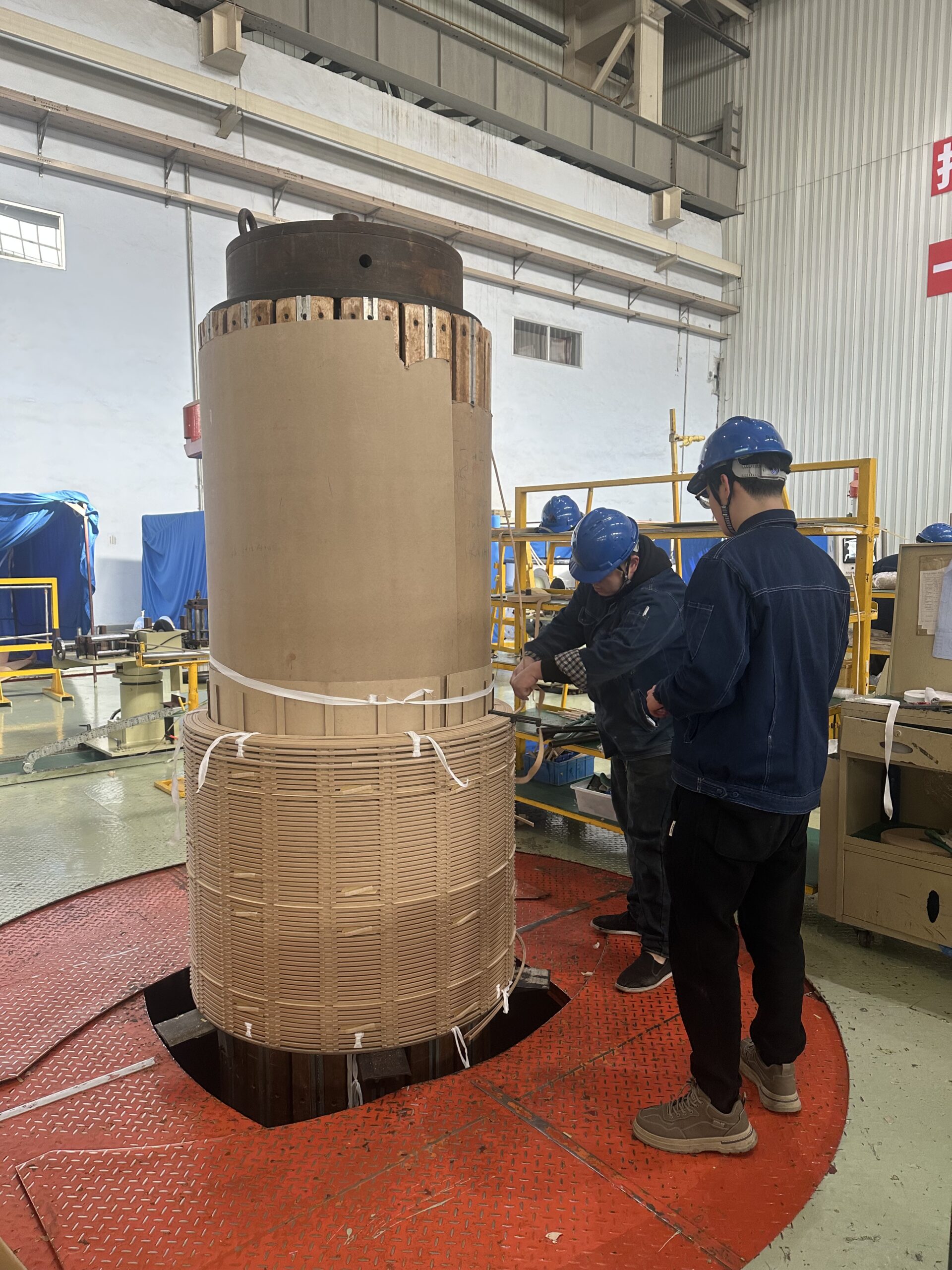
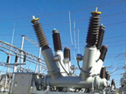
How Does the Oil System Contribute to Transformer Functionality?
![]()
Power transformers are crucial in power distribution systems, stepping up or stepping down voltage to suit various applications. However, the complex nature of transformers demands more than just electrical and magnetic components to operate efficiently. One of the critical, often underestimated, elements that play a vital role in transformer performance is the oil system.
The oil system in a transformer isn't just an accessory — it’s an essential component that directly impacts the transformer's efficiency, reliability, safety, and longevity. Transformer oil, typically mineral oil, serves several important functions, including cooling, insulation, and even providing a medium for preventing corrosion. In this article, we will explore how the oil system contributes to the functionality of a transformer, ensuring that it operates smoothly under a wide range of conditions.
The oil system in a transformer provides cooling and insulation to prevent overheating, facilitate the safe operation of the transformer, and protect the internal components from damage. Transformer oil also acts as a barrier against the ingress of moisture, which could compromise the electrical integrity of the transformer.
Let’s delve deeper into the pivotal roles that transformer oil systems play in maintaining optimal transformer performance.
Cooling: Preventing Overheating
One of the most important functions of transformer oil is to dissipate heat generated by the transformer’s core and windings during operation. Transformers handle large amounts of electrical energy, and as electricity flows through the windings, resistance and losses generate heat. Without proper cooling, excessive temperatures could lead to degradation of the insulation, eventual damage to components, and even transformer failure.
Cooling Mechanism of Transformer Oil
Transformer oil circulates through the transformer, absorbing heat from the core and windings. This heat is then transferred to the oil tank or cooling fins, where it is dissipated into the surrounding environment. The oil acts as a heat exchanger, improving the heat transfer rate by conducting heat away from the components that generate it. Depending on the transformer design, oil cooling may involve:
Natural Cooling (ONAN - Oil Natural Air Natural):
In smaller transformers, the oil naturally circulates due to convection, aided by the ambient air. The warm oil rises to the top of the tank, while cooler oil from the bottom flows into the windings, maintaining a continuous cycle of heat absorption and dissipation.Forced Cooling (ONAF - Oil Natural Air Forced):
For larger transformers, fans or pumps are used to force air or oil through the cooling system, accelerating the heat transfer process. Forced oil circulation can help maintain lower temperatures and is commonly found in high-capacity transformers.Oil-to-Water Cooling (OWT - Oil Water Transformer):
In this system, the oil is cooled by a water-based cooling unit, such as a heat exchanger. This system is typically used for larger, high-power transformers and ensures efficient heat dissipation, particularly in extreme environmental conditions.
Insulation: Enhancing Electrical Safety
In addition to cooling, transformer oil also acts as an insulating medium between the windings and other transformer components. It helps to insulate the windings, preventing short circuits and electrical arcing that could occur if the components came into contact with each other or with the transformer casing.
How Oil Insulates
Transformer oil has high dielectric strength, which means it can withstand high voltages without breaking down. This ability to insulate ensures that the transformer can operate safely at high voltages, preventing electrical breakdowns and the risk of catastrophic failures.
The oil helps to fill gaps between the transformer’s internal components, such as the windings and the core, providing insulation even in areas where solid insulation materials cannot be used.
Over time, the oil can degrade due to heat and electrical stress. Regular oil monitoring and maintenance are required to ensure that its dielectric properties are intact and that it continues to provide reliable insulation.
Preventing Corrosion and Contaminants
Transformer oil also plays a role in preventing the formation of corrosion on internal metal components. Water and oxygen are the main contributors to corrosion, and the oil system forms a barrier to these harmful elements.
Protection Against Moisture and Air
The oil prevents moisture from entering the transformer by forming a seal around the internal components. Any moisture present in the oil can be harmful, leading to the breakdown of the oil’s insulating properties. Therefore, regular oil filtration and testing are necessary to remove moisture from the oil and ensure that it remains effective.
In addition to preventing moisture ingress, the oil system also helps to displace air from inside the transformer. This minimizes the risk of oxidation, which can degrade the oil and reduce its ability to protect the transformer components.
Gas Absorption and Arc Quenching
In transformers, especially in higher-capacity units, the potential for arcing or electrical faults exists. When electrical faults occur, gas formation within the transformer oil can occur due to the high energy levels involved. Transformer oil helps absorb the gases and, in some cases, extinguishes arcs.
Arc-Quenching Properties
In the event of a fault, the oil’s arc-quenching properties help to reduce the likelihood of damage from electrical arcs. The oil helps to cool down and quench any arcing that occurs during faults, preventing further damage to the windings or core.
In the event of gas buildup due to electrical faults, gas-activated relays can detect abnormal gas production within the oil, signaling the need for intervention before serious damage occurs.
Enhancing Longevity and Reliability
Transformer oil’s role in cooling, insulation, and protection extends the lifespan of the transformer. Without an effective oil system, the transformer would overheat, experience electrical failures, or degrade prematurely.
Extended Transformer Life
The oil continuously cools the transformer, preventing it from overheating and extending its life cycle. Regular oil monitoring, filtration, and replacement ensure that the oil remains free of contaminants, moisture, and degradation, allowing the transformer to function reliably for many years.
Proper oil maintenance, including regular testing for acidity, dielectric strength, and moisture content, is crucial in ensuring that the oil maintains its protective properties.
ClaimReview fact check in the text.
Transformer oil prevents overheating by acting as a coolant and reducing the temperature of the transformer components.True
Transformer oil circulates within the transformer, absorbing heat from the windings and core. The heat is then dissipated through cooling fins or other systems, preventing overheating and ensuring safe operation.
What is the Purpose of the Tap Changer in Power Transformers?
Power transformers are essential devices in electrical grids, responsible for stepping up or stepping down voltage levels to ensure that electricity can be distributed efficiently over long distances. While the core function of any transformer is to change voltage, achieving precise voltage regulation under different loading conditions is not always straightforward. This is where the tap changer comes into play.
A tap changer is a critical device in a power transformer that allows for the adjustment of the transformer's voltage ratio. It ensures that the transformer can operate efficiently and maintain a stable output voltage, regardless of fluctuations in the load or supply voltage. Without a tap changer, maintaining constant voltage would be difficult, leading to voltage instability and potential damage to electrical equipment.
Tap changers in power transformers allow operators to regulate the transformer's output voltage by selecting different voltage taps on the windings. This provides flexibility in adjusting the transformer’s voltage ratio to accommodate changes in the power grid or load demands, ensuring reliable operation and preventing voltage fluctuations.
Let’s dive into the primary purpose of the tap changer in a power transformer and explore how it works to maintain voltage stability.
Voltage Regulation: Ensuring Stable Output Voltage
The main function of the tap changer is voltage regulation. Since the primary role of a transformer is to either step up or step down voltage, maintaining a stable output voltage under varying load conditions is crucial. The voltage ratio between the primary and secondary windings of the transformer depends on the number of turns in each winding. The tap changer adjusts this ratio by selecting different "taps" on the winding.
How Voltage Regulation Works
Tap Changing Mechanism: A tap changer allows the operator to switch between different taps on the transformer's windings. These taps correspond to different turns of the winding, altering the voltage ratio to either increase or decrease the output voltage. By selecting the appropriate tap, the transformer can compensate for fluctuations in the input voltage, ensuring that the output remains stable and within the required range.
Load Conditions: When there is a change in the load connected to the transformer (such as an increase in power demand), the secondary voltage may fluctuate. By adjusting the tap changer, operators can correct these fluctuations, ensuring that the voltage supplied to the load remains consistent and within acceptable limits.
Off-Load and On-Load Tap Changers: Tap changers come in two types: off-load and on-load. Off-load tap changers require the transformer to be disconnected from the circuit before adjustments can be made, while on-load tap changers can adjust the voltage while the transformer is still operating and supplying power to the grid. On-load tap changers are particularly useful in ensuring continuous voltage stability in dynamic grid conditions.
Compensation for Supply Voltage Variations
In an electrical grid, the supply voltage may fluctuate due to various factors such as changes in the input power or disturbances in the grid. These fluctuations can lead to undesirable consequences, such as overvoltage or undervoltage, which may damage electrical equipment or cause operational inefficiencies.
How Tap Changers Compensate for Supply Variations
Overvoltage Prevention: In cases where the supply voltage increases beyond the desired level, the tap changer can select a lower voltage tap to reduce the output voltage, thus preventing overvoltage and potential damage to connected equipment.
Undervoltage Prevention: Conversely, if the supply voltage drops below the required level, the tap changer can select a higher voltage tap to compensate for the lower supply voltage, ensuring that the transformer provides the correct voltage to the load.
Fine-Tuning Voltage Levels: In some cases, minor adjustments to the voltage may be needed to maintain optimal performance. The tap changer allows for fine-tuning, ensuring that the transformer delivers a precise output voltage that meets the requirements of the connected load.
Improving Transformer Efficiency
By enabling voltage regulation, tap changers help transformers operate more efficiently. In an electrical grid, transformers are often subjected to variable loads and input voltages. Without voltage regulation, transformers would need to operate at a fixed voltage ratio, leading to energy loss, inefficiency, and potential overheating.
How Tap Changers Enhance Efficiency
Reduced Energy Losses: With precise voltage regulation, the transformer can operate closer to its optimal efficiency, minimizing energy losses. This ensures that electrical energy is delivered to the load with minimal waste.
Improved Performance Under Variable Conditions: In power grids with fluctuating loads, tap changers enable transformers to adapt to changes in demand, ensuring that the system operates efficiently even under varying conditions.
Minimizing Transformer Stress
Voltage fluctuations and overloading can put significant stress on a transformer, potentially leading to overheating, insulation degradation, or premature failure. The tap changer helps mitigate these risks by keeping the transformer’s operating conditions within a safe and stable range.
Protecting the Transformer from Damage
Reducing Overload Risks: By adjusting the voltage in response to load changes, the tap changer helps prevent the transformer from being exposed to excessive electrical stress. This reduces the likelihood of overheating and extends the lifespan of the transformer.
Optimizing the Load Distribution: In some cases, the tap changer may be used to distribute the load more evenly across the transformer’s windings, reducing localized heating and ensuring that the transformer operates within its design limits.
Types of Tap Changers
There are two primary types of tap changers used in power transformers: on-load tap changers (OLTCs) and off-load tap changers (OLTCs). Each type has specific advantages and applications depending on the transformer’s requirements.
On-Load Tap Changers (OLTC)
Continuous Operation: On-load tap changers can adjust the voltage ratio while the transformer is under load and supplying power. This capability is essential for maintaining continuous voltage regulation in real-time.
Automatic Adjustment: In many modern transformers, OLTCs are equipped with automatic voltage regulators that can adjust the tap position automatically based on real-time voltage measurements, ensuring continuous voltage stability.
Off-Load Tap Changers
Manual Adjustment: Off-load tap changers require the transformer to be disconnected from the grid before any voltage adjustment can be made. They are typically used for applications where the voltage does not need to be adjusted frequently.
Simpler Design: Off-load tap changers are simpler and cost-effective compared to OLTCs, but they are less flexible and do not allow for real-time voltage regulation.
ClaimReview fact check in the text.
Tap changers ensure that the transformer operates efficiently and maintains a stable output voltage, even under varying load and supply voltage conditions.True
Tap changers adjust the voltage ratio of the transformer to regulate the output voltage, compensating for fluctuations in supply voltage and load changes. This ensures stable and efficient operation of the transformer.
How Do Other Auxiliary Components (Bushings, Conservators, etc.) Support Transformer Operation?
A power transformer is a sophisticated piece of equipment that relies on several essential auxiliary components to function properly and maintain its operational efficiency. While the core and windings of a transformer are the primary components responsible for voltage conversion, auxiliary components like bushings, conservators, breathers, cooling systems, and radiators all play critical roles in ensuring the transformer's reliable and long-term operation. Without these supporting components, transformers could face numerous issues, from electrical faults to overheating, leading to potential system failures.
In this article, we'll explore the essential role of these auxiliary components, including bushings, conservators, and more, in supporting power transformer operation and performance.
Auxiliary components, such as bushings, conservators, breather, cooling systems, and radiators, are essential for the reliable operation of power transformers. They support the transformer's electrical insulation, manage temperature fluctuations, prevent oil contamination, and ensure safety during operation.
Bushings: Ensuring Safe Electrical Connection
Bushings are an integral part of any power transformer, providing a safe and insulated pathway for electrical conductors to pass through the transformer's tank. They help maintain the integrity of the transformer by ensuring that electrical connections are made without compromising the transformer’s internal insulation.
How Bushings Work
Insulated Pathways: Bushings serve as insulators that allow the electrical connections between the transformer's internal components (e.g., the primary and secondary windings) and the external power lines. These bushings must have high dielectric strength to prevent electrical breakdown and to protect the transformer from electrical faults.
Types of Bushings: Depending on the voltage class and design, transformers may use different types of bushings, including porcelain, resin, and oil-impregnated bushings. Each type of bushing is chosen based on the transformer’s voltage rating, the environmental conditions, and the need for insulation and safety.
Protection from Electrical Faults: Bushings are designed to withstand electrical stresses and ensure that no electrical leakage occurs. They help prevent faults due to external factors like electrical surges or system overvoltages.
Sealing Oil Systems: In oil-filled transformers, bushings are equipped with seals to prevent oil leaks, ensuring that the transformer's oil system remains intact. Any loss of insulating oil could compromise the transformer's performance and safety.
Conservators: Managing Oil Level and Temperature
Transformers, especially oil-filled types, rely on conservators to maintain the oil level and ensure effective cooling. The oil inside the transformer serves as an insulator and coolant, dissipating heat generated by the electrical load.
How Conservators Support Transformer Functionality
Oil Expansion and Contraction: As the transformer operates, the insulating oil heats up and expands. The conservator provides extra space for the oil to expand and contract without spilling over or damaging the system. This expansion and contraction occur due to temperature variations during operation.
Maintaining Oil Level: Conservators typically consist of a sealed tank connected to the main transformer tank, containing a diaphragm or bladder to separate the oil from external contaminants. This separation ensures that the oil remains clean and free from moisture, which could degrade its insulating properties.
Preventing Contamination: The conservator often features a breather (more on that below) to prevent moisture from entering the oil system. Moisture in the transformer oil can significantly reduce its dielectric strength and insulation properties, leading to operational inefficiencies and failures.
Enhanced Cooling: The oil in the conservator also assists in cooling the transformer. As the oil moves between the main tank and the conservator, it helps to dissipate heat, preventing overheating, which could otherwise lead to transformer damage.
Breather: Preventing Moisture and Air Contamination
The breather is another vital auxiliary component designed to ensure the cleanliness of the transformer’s oil. It prevents moisture and air from entering the transformer’s oil system, safeguarding the oil’s insulating properties.
How the Breather Works
Moisture Control: The breather is typically filled with silica gel, a material that absorbs moisture. As the transformer oil moves between the main tank and the conservator during temperature fluctuations, air from the outside could enter the system. Without a breather, this air could contain moisture that could harm the oil and reduce the transformer's dielectric strength.
Air Quality: In addition to moisture, the breather helps maintain air quality inside the transformer’s oil system by preventing contamination from dirt or debris. Keeping the air clean ensures that the transformer’s oil does not degrade over time.
Indicator for Oil Condition: Many breather systems include a moisture indicator, signaling when the silica gel has absorbed enough moisture to be replaced. This is crucial for maintaining the transformer's insulation properties.
Cooling Systems: Preventing Overheating
As transformers operate under load, they generate heat, and maintaining an optimal operating temperature is critical for both performance and longevity. Cooling systems, including oil cooling, air cooling, and fans, help dissipate the heat generated during operation.
Types of Cooling Systems
Oil Cooling: In many oil-filled transformers, the oil itself circulates through the transformer to absorb heat from the core and windings. The oil is then passed through radiators or heat exchangers to release this heat into the surrounding environment.
Air Cooling: Some transformers use air-based cooling systems to complement oil cooling. Fans are used to force air over the surface of the transformer, improving heat dissipation.
Fans and Pumps: For larger transformers, cooling systems may include fans, pumps, and heat exchangers to maintain the oil temperature within safe operating limits. This is particularly important for transformers that experience high load conditions and need enhanced cooling.
Radiators: The oil in the transformer moves through the radiators where heat is transferred from the oil to the air. These radiators come in various forms, including natural convection radiators (for small transformers) and forced cooling radiators (for larger, high-capacity transformers).
Pressure Relief Valve: Ensuring Safety and Preventing Damage
Transformers, especially oil-filled ones, operate under high pressure. A pressure relief valve is used to ensure that excessive pressure does not build up inside the transformer, potentially causing damage to the tank or the insulation.
Functionality of the Pressure Relief Valve
Pressure Control: As the transformer heats up, the oil inside the tank expands. If the pressure becomes too high, the pressure relief valve releases excess pressure to prevent damage to the transformer tank. This ensures that the transformer operates safely, even during conditions of extreme heat.
Safety: The pressure relief valve is critical for ensuring that the transformer is safe during abnormal conditions, such as a short circuit or internal fault. It helps to protect the integrity of the transformer by preventing a dangerous buildup of pressure.
Conclusion
The internal structure of a power transformer is designed with precision to ensure efficient voltage transformation, electrical isolation, and safe operation. Its core, windings, oil system, tap changer, and auxiliary components all work together to transfer electrical energy between circuits while regulating voltage levels. The core and windings enable electromagnetic induction, which is essential for transforming voltage. The oil system ensures cooling and insulation, preventing overheating and breakdown of components. Additionally, the tap changer and other components such as bushings, conservators, and protection devices help regulate voltage and safeguard the transformer’s performance under various conditions.
In essence, understanding the internal structure and functioning of a power transformer reveals how it supports the broader electrical grid, ensuring that electricity is delivered efficiently, safely, and reliably to consumers. Each element of the transformer is designed to withstand various stresses and environmental conditions, ensuring long-term performance and grid stability.
FAQ
Q1: What is the internal structure of a power transformer?
A1: The internal structure of a power transformer consists of several key components: the core, primary and secondary windings (coils), insulating materials, and the tank. The core is typically made of laminated steel sheets, while the windings are copper or aluminum coils that carry electrical current.
Q2: How does a power transformer work?
A2: A power transformer works based on electromagnetic induction. When alternating current (AC) flows through the primary winding, it generates a magnetic field. This magnetic field induces a current in the secondary winding, which results in a change in voltage depending on the turn ratio between the windings.
Q3: What is the role of the core in a power transformer?
A3: The core of a power transformer provides a path for the magnetic flux generated by the primary winding. It is usually made from laminated sheets of steel to reduce energy losses due to eddy currents. The core's role is crucial in efficiently transferring electrical energy from the primary to the secondary winding.
Q4: What materials are used in a power transformer?
A4: The primary and secondary windings of a transformer are typically made from copper or aluminum, which are excellent conductors. The core is often made of laminated steel to reduce energy losses. Insulating materials such as oil or paper are used to prevent short circuits and ensure safety.
Q5: How is voltage regulation achieved in a power transformer?
A5: Voltage regulation in a power transformer is achieved by adjusting the turns ratio between the primary and secondary windings. By increasing or decreasing the number of turns in each coil, the transformer can step up or step down the voltage to the desired level while maintaining efficiency.