Selecting the right transformer is a crucial step in ensuring the safe, efficient, and reliable operation of electrical systems. Whether for industrial facilities, commercial buildings, or utility networks, the transformer must meet the electrical load demands, environmental conditions, and regulatory standards of the application. Making the wrong choice can lead to energy inefficiencies, frequent maintenance, or even system failure. This guide outlines the key considerations for choosing the right transformer based on performance, type, and application needs.
What Are the Load Requirements?
For a distribution transformer to operate reliably, efficiently, and safely, it must be properly matched to the load it serves. Load requirements dictate not just the transformer's kVA rating but also its cooling system, winding design, voltage stability, and protection schemes. Overloading, underloading, and unbalanced loading can each lead to performance degradation, reduced lifespan, or even failure.
Load requirements for transformers refer to the anticipated electrical demand (in kVA), voltage level, phase configuration, load type (resistive, inductive, or nonlinear), load growth expectations, and loading profile (peak vs. average). A correctly rated transformer should operate efficiently under full load, tolerate short-term overloads, and maintain voltage regulation without overheating or distortion.
This article explains how to define, calculate, and manage load requirements to ensure that distribution transformers perform as intended over their operational life.
Transformer load requirements must consider kVA demand, load type, duty cycle, and voltage balance to ensure proper sizing and reliability.True
Load conditions directly affect the transformer's core and winding performance, cooling, and long-term operational safety.
As long as voltage matches, any transformer can serve any load regardless of size or type.False
Transformers must be sized and configured to match the specific electrical characteristics and demands of the load to avoid inefficiencies or damage.
1. Rated Load (kVA Capacity)
Definition:
The rated load is the maximum continuous apparent power the transformer can supply without exceeding its temperature rise limit.
| Factor | Description |
|---|---|
| Unit | Kilovolt-amperes (kVA) |
| Based on | Copper losses (I²R) + Core losses (no-load) |
| Limit | Set by insulation class and cooling design |
Example:
- A 250 kVA transformer can continuously supply a balanced 250 kVA load at nominal voltage and frequency, without overheating.
2. Load Type Considerations
| Load Type | Characteristics | Transformer Impact |
|---|---|---|
| Resistive | Heaters, incandescent lights | Stable, low inrush, steady voltage |
| Inductive | Motors, compressors, pumps | High inrush current, reactive power |
| Capacitive | Power factor correction banks | Risk of overvoltage |
| Non-linear | Computers, VFDs, UPS systems | Generates harmonics, overheating risk |
Transformers serving nonlinear loads may require K-rating or harmonic mitigation to avoid excess heating.
3. Duty Cycle and Load Duration Curve
Key Concepts:
- Peak Load: Highest instantaneous demand
- Average Load: Long-term mean usage
- Load Factor: Ratio of average to peak load
- Diversity Factor: Accounts for non-simultaneous usage among consumers
| Duty Type | Load Profile | Transformer Implication |
|---|---|---|
| Continuous duty | Constant industrial machinery | Requires robust cooling and insulation |
| Intermittent duty | School or hospital operation | Allows slight overload buffer |
| Cyclical/diurnal load | Residential, commercial | Optimized sizing with safety margin |
Undersizing risks overheating, while oversizing leads to poor efficiency and high no-load losses.
4. Voltage and Phase Matching
| Load Type | Voltage Requirement | Phase Requirement |
|---|---|---|
| Residential (single-phase) | 230 V ±5% | Single-phase (1Φ) |
| Commercial | 400 V (line-line) | Three-phase (3Φ) |
| Light Industrial | 400/230 V | Balanced 3Φ preferred |
| Large Industrial | 690 V or higher | Requires special configuration |
Vector Group Matching:
- Dyn11 (Δ/Y, 30° phase shift) is the standard for balanced 3-phase low-voltage output
5. Unbalanced Load Considerations
Unbalanced loads create neutral shift, voltage distortion, and heating in the windings.
| Problem | Result |
|---|---|
| Single-phase overloading | Overheating in one limb or phase |
| Neutral current overload | High zero-sequence current |
| Poor load balancing | Degraded efficiency and voltage drop |
Load balancing across phases is crucial for three-phase transformers.
6. Overload Capacity and Short-Term Loading
Per IEC/ANSI:
Transformers may operate above rated kVA temporarily:
- 10% overload for 2 hours
- 25% overload for 30 minutes
- Dependent on ambient temperature and cooling
| Overload Margin | Permissible Duration |
|---|---|
| 10% | Up to 2 hours |
| 25% | 30–60 minutes max |
| >30% | Requires design consideration |
Repeated overloads accelerate insulation aging and reduce lifespan.
7. Transformer Sizing for Load
Steps for Load-Based Sizing:
- Calculate total connected load (kW or kVA)
- Apply diversity and load factor
- Add future growth margin (\~10–25%)
- Select nearest standard kVA rating (e.g., 250, 400, 630 kVA)
| Scenario | Total Load (kVA) | Selected Transformer |
|---|---|---|
| Small residential area | 180 kVA | 250 kVA |
| Office building | 420 kVA | 500 kVA |
| Light manufacturing unit | 980 kVA | 1000 or 1250 kVA |
8. Real-World Load Profiles
| Sector | Load Type | Load Profile |
|---|---|---|
| Residential | Mixed resistive/inductive | Evening peak, diurnal dip |
| Commercial | Inductive/Nonlinear | Steady daytime load |
| Rural | Motor-heavy (pumps) | Morning and evening peaks |
| Data centers | Nonlinear + backup loads | 24/7, constant with UPS |
Accurate profiling helps select proper transformer size, cooling, and vector group.
Summary Table: Transformer Load Requirements
| Requirement Aspect | Key Consideration |
|---|---|
| Rated Capacity | Match total kVA with margin |
| Load Type | Determine resistive, inductive, or nonlinear |
| Load Profile | Evaluate duty cycle and diversity |
| Voltage and Phase | Match output voltage, phase type |
| Harmonics and Unbalance | Consider K-rating or phase balancing |
| Overload Capacity | Understand permissible short-term limits |
| Future Expansion Margin | Add 10–25% to accommodate growth |
What Type of Transformer Best Fits the Application?
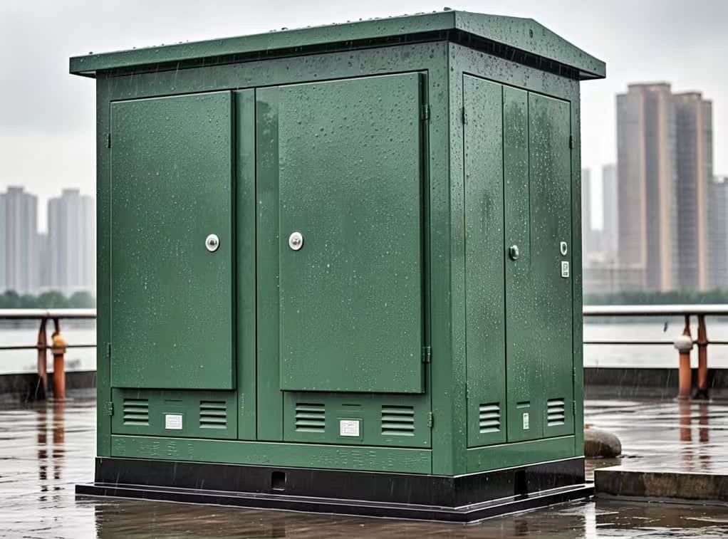
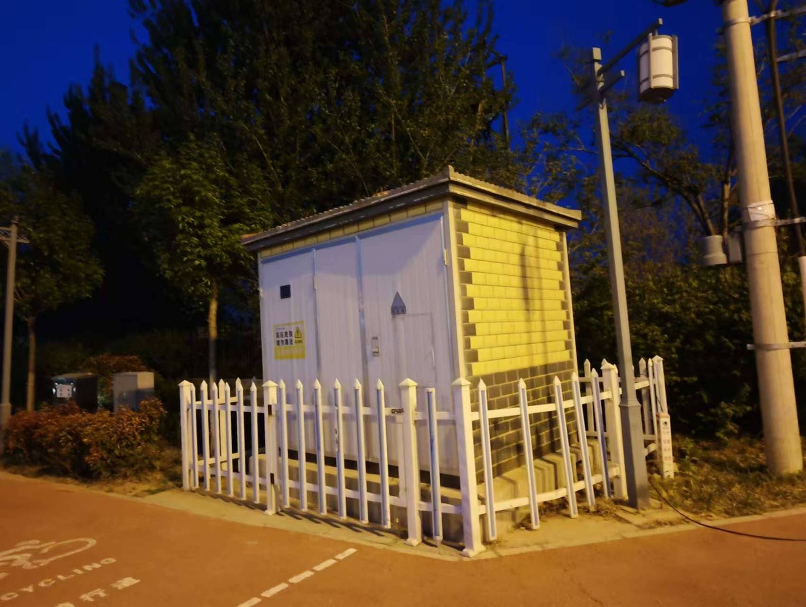
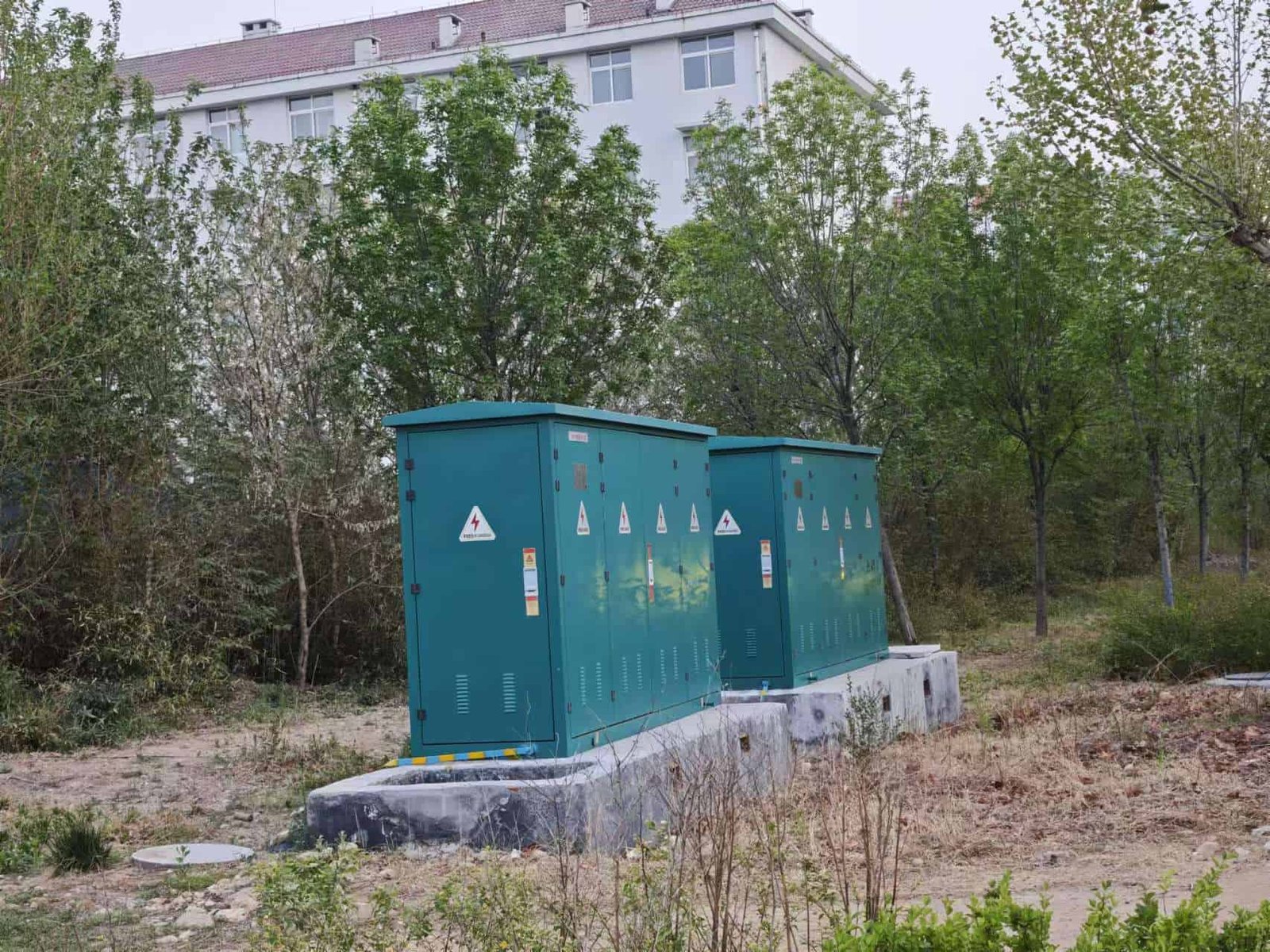
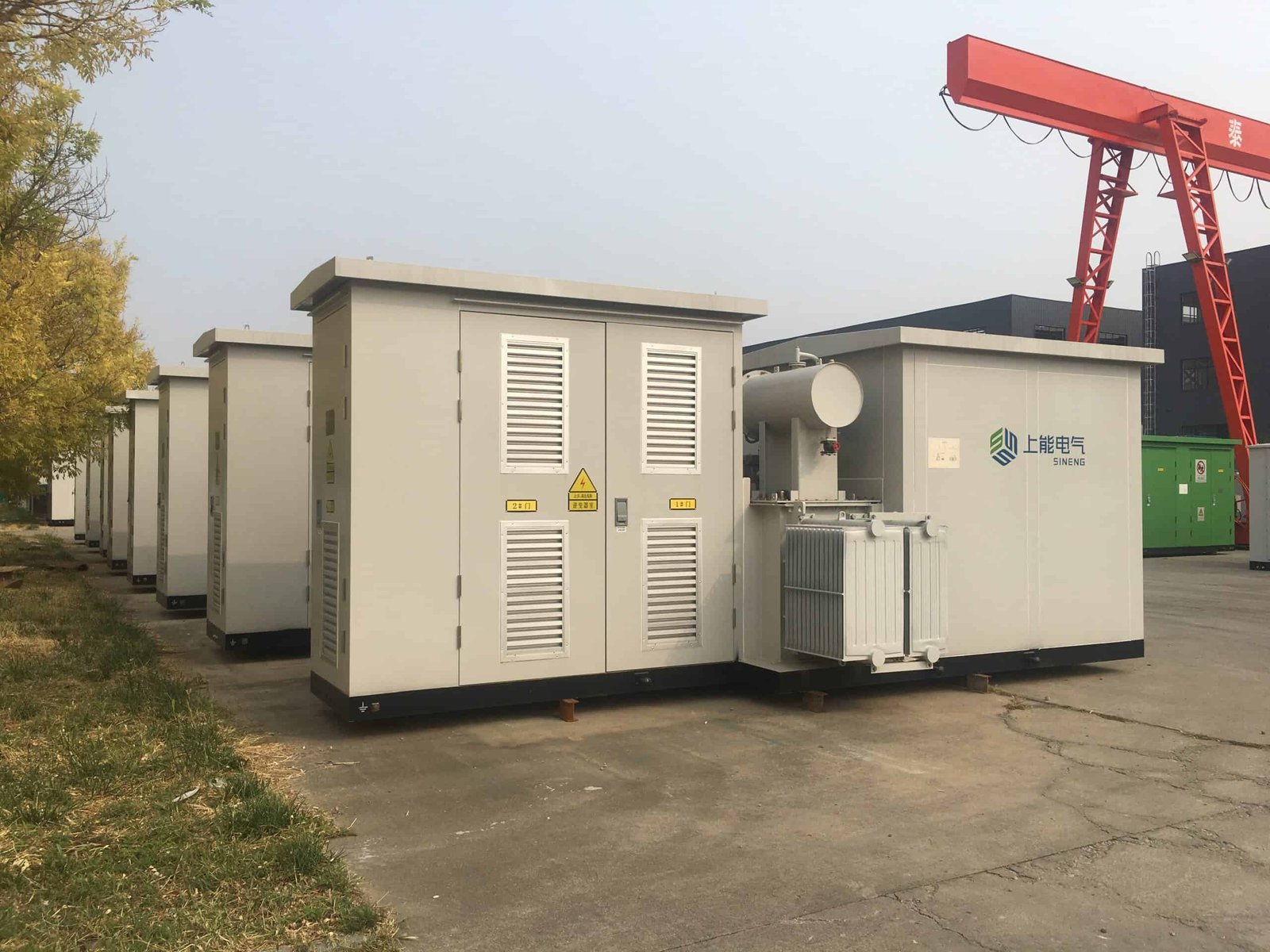
Choosing the right transformer for a specific application is not a one-size-fits-all decision—it’s a multi-criteria engineering analysis. Factors like power capacity, environment, voltage levels, load type, cooling needs, installation location, and safety constraints determine whether an oil-immersed, dry-type, pole-mounted, or pad-mounted transformer is most suitable. Selecting the wrong type can lead to inefficiency, increased maintenance, and even safety hazards.
The best transformer type for an application depends on key factors including load size (kVA), environmental conditions (indoor vs. outdoor), voltage requirements, safety standards, space constraints, and installation type. Oil-immersed transformers are preferred for outdoor high-capacity loads, while dry-type units are used indoors or in fire-sensitive areas. Pole-mounted units suit rural distribution, pad-mounted transformers fit urban settings, and single- vs. three-phase depends on the power system configuration.
This article breaks down the process of transformer selection by application scenario and outlines which transformer type is best suited for each environment.
Selecting the appropriate transformer type depends on application-specific factors such as load demand, location, safety, and environmental conditions.True
Choosing the right transformer type optimizes performance, minimizes risk, and ensures compliance with operational requirements.
All transformer types can be used interchangeably regardless of the load or environment.False
Transformers must be selected based on design compatibility with the specific voltage, power, cooling, and safety needs of the application.
1. Oil-Immersed vs. Dry-Type Transformers
| Feature | Oil-Immersed Transformer | Dry-Type Transformer |
|---|---|---|
| Cooling Medium | Mineral oil, natural convection | Air-cooled or resin-encapsulated |
| Installation | Outdoor, substations | Indoor, basements, fire-risk zones |
| Typical Rating Range | 16–2500 kVA | 25–1600 kVA |
| Fire Risk | Medium (flammable oil) | Low (fire-retardant) |
| Maintenance | Requires oil testing | Lower maintenance needs |
| Cost | More economical | Higher initial cost |
Best Fit:
- Use oil-immersed transformers for utility-scale outdoor applications
- Use dry-type transformers for indoor or environmentally sensitive installations
2. Pole-Mounted vs. Pad-Mounted Transformers
| Feature | Pole-Mounted | Pad-Mounted |
|---|---|---|
| Installation | Mounted on distribution poles | Ground-mounted, in tamper-proof enclosures |
| Common Use | Rural electrification | Urban commercial/residential |
| Voltage Range | Up to 33 kV primary | Typically 11 or 33 kV primary |
| Capacity Range | 10–250 kVA | 100–2500 kVA |
| Safety/Accessibility | Requires climbing or lift | Ground-level servicing |
Best Fit:
- Use pole-mounted transformers for low-density, rural areas
- Use pad-mounted transformers for urban or high-traffic environments
3. Single-Phase vs. Three-Phase Transformers
| Feature | Single-Phase | Three-Phase |
|---|---|---|
| Load Type | Residential, low-load areas | Commercial, industrial, large buildings |
| Output Voltage | 230 V (line-to-neutral) | 400 V (line-to-line), 230 V (line-to-neutral) |
| Power Range | 5–100 kVA | 100–2500 kVA |
| Cost | Lower | Higher |
| System Balance | Prone to imbalance | Provides load balance and higher efficiency |
Best Fit:
- Choose single-phase for remote homes or farms
- Choose three-phase for any balanced or high-load environment
4. Application-Based Transformer Selection
| Application Area | Recommended Transformer Type | Reason |
|---|---|---|
| Urban commercial zone | Dry-type, pad-mounted, 3-phase | Fire safety, compact design |
| Rural power distribution | Oil-immersed, pole-mounted, single-phase | Cost-effective, easy installation |
| Hospital/School | Dry-type, 3-phase, indoor | Quiet, safe, and efficient |
| Data center | K-rated dry-type, 3-phase | Handles harmonics, high reliability |
| Industrial factory | Oil-filled, pad-mounted or outdoor | High-capacity, 3-phase load support |
| Temporary site | Trailer-mounted oil-filled | Mobile, flexible installation |
5. Environment and Safety Considerations
| Environment | Best Transformer Type | Justification |
|---|---|---|
| High humidity/corrosive | Sealed oil-immersed (stainless tank) | Oil provides sealed protection |
| Fire-risk facility | Dry-type (Class F or H insulation) | No flammable oil |
| Underground vault | Dry-type or sealed pad-mounted | Ventilation and safety compliant |
| Coastal regions | Oil-immersed with anticorrosive coating | Salt-resistant with proper enclosure |
6. Cooling and Load Profile Matching
| Load Pattern | Best Cooling Type | Recommended Transformer |
|---|---|---|
| Constant 24/7 load | ONAN oil-filled | High efficiency, good heat transfer |
| Intermittent daytime use | Dry-type AN | Lower heat accumulation, safer indoors |
| High-ambient environment | ONAF with fans | Enhanced heat dissipation |
Summary Table: Matching Transformer Type to Application
| Parameter | Best Transformer Type |
|---|---|
| Outdoor, high-capacity | Oil-immersed, pad-mounted, 3-phase |
| Indoor, commercial use | Dry-type, low-noise, compact |
| Rural or remote area | Oil-immersed, pole-mounted |
| Sensitive facility | Dry-type, Class F/H, shielded |
| Heavy industrial loads | Oil-immersed, robustly cooled |
| Temporary/mobile setup | Trailer-mounted oil or dry type |
| Harmonic-prone loads | K-rated dry-type transformer |
What Voltage Levels Are Involved?
Voltage levels play a central role in the planning, design, and operation of transformers and power systems. Transformers are specifically engineered to step up or step down voltage across defined levels, matching generation and transmission with the final usage demands. Understanding these levels is essential for selecting the right transformer, ensuring system compatibility, and meeting regulatory or utility requirements.
Voltage levels involved in power systems typically include generation voltage (11–25 kV), transmission voltage (66–765 kV), sub-transmission voltage (33–132 kV), and distribution voltage (11, 6.6, or 3.3 kV for primary; 415/230 V for secondary). Distribution transformers convert medium voltage (typically 11 or 33 kV) to low voltage (400/230 V) for end-user applications. Each voltage level corresponds to a specific grid tier and transformer function.
This article explains the voltage hierarchy in electrical systems and shows how transformers operate across these levels to ensure efficient power delivery.
Transformers operate across multiple voltage levels to match generation, transmission, and distribution stages of the power grid.True
Each transformer in the power grid is designed to handle specific voltage transitions—stepping up for transmission and stepping down for end-user delivery.
All transformers operate at the same voltage level regardless of their location in the grid.False
Transformers are classified and designed based on the voltage levels at their point of use within the electrical network.
1. Voltage Classifications in Power Systems
| Voltage Class | Voltage Range | Application Stage |
|---|---|---|
| Low Voltage (LV) | 230/400 V | Final user distribution |
| Medium Voltage (MV) | 1 kV – 33 kV | Primary distribution |
| High Voltage (HV) | 66 kV – 220 kV | Transmission/Sub-transmission |
| Extra High Voltage (EHV) | 220 kV – 400 kV | Long-distance transmission |
| Ultra High Voltage (UHV) | > 400 kV (up to 765 kV) | Bulk transmission systems |
Transformers are used at every stage to maintain voltage levels suitable for system performance and equipment safety.
2. Transformer Types by Voltage Application
| Transformer Type | Input Voltage (kV) | Output Voltage (kV) | Use Stage |
|---|---|---|---|
| Generator Step-Up (GSU) | 11–25 | 132–765 | Power generation to transmission |
| Transmission Transformer | 400/220 | 132–66 | EHV to HV sub-transmission |
| Sub-transmission Transformer | 66–33 | 33–11 | Regional distribution |
| Distribution Transformer | 33/11 | 0.4/0.23 | Final voltage conversion |
| Instrument Transformer | High voltage | Millivolt or ampere ranges | Measurement and protection |
3. Common Voltage Levels in Distribution Transformers
| Country/Region | Primary (MV) Voltage | Secondary (LV) Voltage |
|---|---|---|
| United States | 4.16 / 13.2 / 24.9 kV | 208Y/120 V or 480Y/277 V |
| Europe (IEC) | 11 / 20 / 33 kV | 400 V / 230 V |
| India | 11 / 22 / 33 kV | 415 V / 230 V |
| Japan | 6.6 kV | 100 / 200 V |
| Middle East | 11 / 33 kV | 400 / 230 V |
Transformers are customized to national grid codes and local voltage distribution standards.
4. Voltage Level Functions and Their Role
| Voltage Level | Function | Reason for Use |
|---|---|---|
| Generation (11–25 kV) | Initial power output from generators | Efficient interface with GSU transformers |
| Transmission (132–765 kV) | Long-distance bulk transport | Reduces current, minimizes I²R losses |
| Distribution Primary (11–33 kV) | Supplies neighborhoods, substations | Localized voltage control |
| Distribution Secondary (230/400 V) | End-user delivery (homes, offices) | Safe for appliances and consumer use |
5. Transformer Voltage Ratio Examples
| Transformer Type | Voltage Ratio | Use Case |
|---|---|---|
| Step-Up (GSU) | 11/220 kV | Generator to transmission grid |
| Step-Down Transmission | 220/33 kV | Bulk to regional substations |
| Distribution | 11/0.415 kV | Pole or pad-mounted for buildings |
| Isolation Transformer | 400/400 V | Galvanic separation in equipment |
| Industrial Transformer | 33/6.6 kV | Feeds motors or large machinery |
6. Voltage Limits and Tolerances
| Voltage Level | Standard Tolerance (%) | Regulated Standard |
|---|---|---|
| Low Voltage (400/230 V) | ±5% or ±10% | IEC 60038 / IS 12360 |
| Medium Voltage (11–33 kV) | ±6% | Utility-specific grid codes |
| Transmission (>66 kV) | ±10% max excursion allowed | National grid codes |
Voltage regulation is critical to avoid insulation stress, equipment malfunction, or overheating.
7. Voltage Consideration in Transformer Selection
| Selection Factor | Voltage Impact |
|---|---|
| Core design | Must withstand peak voltages and surges |
| Insulation class | Rated for operating + overvoltage margin |
| Bushing rating | Matches primary and secondary voltage class |
| Tap changer range | ±5% voltage tuning for regulation |
Voltage defines the entire electrical stress profile and determines many design decisions.
Summary Table: Voltage Levels and Transformer Roles
| Grid Stage | Typical Voltage | Transformer Role |
|---|---|---|
| Power Generation | 11–25 kV | Step-up (GSU) to transmission level |
| Long Transmission | 132–765 kV | Transmission step-down transformers |
| Sub-Transmission | 66 / 33 / 22 kV | Feeds primary distribution systems |
| Distribution Primary | 11 kV | Input to pole or pad-mounted transformers |
| Distribution Secondary | 400 V / 230 V | End-user voltage level for homes/offices |
What Are the Environmental Conditions?
Transformers are designed not only to handle electrical loads but also to withstand a wide range of environmental conditions that can significantly affect their performance, lifespan, safety, and maintenance needs. From humid tropics to icy mountain zones, and from corrosive coastal regions to dusty industrial areas, each operating environment imposes specific mechanical, thermal, and chemical stresses on transformer components. Ignoring these factors can result in premature aging, insulation failure, or even catastrophic breakdowns.
Environmental conditions for transformers include temperature extremes, humidity, altitude, air pollution (such as dust or chemical contaminants), seismic activity, UV exposure, salt fog (coastal areas), and flooding risk. These factors influence transformer design, material selection, enclosure type, cooling method, and protection level. To ensure reliable performance, transformers must be adapted or rated according to their specific environmental category.
This article provides a comprehensive guide to the environmental conditions that affect transformer performance and how engineers and planners account for them in specification and deployment.
Environmental conditions such as temperature, humidity, pollution, and altitude significantly affect transformer performance and reliability.True
These factors influence insulation aging, cooling effectiveness, corrosion risk, and dielectric stress, requiring specific design adaptations.
Environmental conditions have little impact on transformers because they are sealed systems.False
Even sealed transformers are influenced by ambient temperature, humidity, and pollution, which affect thermal dissipation and mechanical durability.
1. Ambient Temperature
| Temperature Category | Typical Range | Design Implication |
|---|---|---|
| IEC Standard Ambient | –5°C to +40°C (average 30°C) | Standard transformer insulation classes |
| Cold climate | Below –20°C | Requires cold-start oil, low-temp seals |
| Hot climate (desert) | Up to +55°C | Needs upgraded cooling (ONAF), UV shielding |
Impact:
- Affects cooling system performance
- Higher temps accelerate insulation aging
- Low temps can increase oil viscosity, impeding flow
IEC 60076-1 allows design adjustments for non-standard temperature zones.
2. Humidity and Moisture
| Humidity Level | Concern | Adaptation Required |
|---|---|---|
| High (≥90%) | Accelerates insulation moisture absorption | Use of sealed or dry-type transformers |
| Rain-prone areas | Risk of water ingress, flashovers | IP-rated enclosures, hydrophobic bushings |
| Tropical conditions | Mold growth, corrosion | Anti-fungal varnish, heater provision |
Moisture is the primary cause of insulation breakdown in paper and oil systems.
3. Altitude
| Altitude Range | Effect on Transformer | Correction Factor (IEC 60076-1) |
|---|---|---|
| 0–1000 m | Standard rating | No derating |
| 1000–2000 m | Reduced air cooling, dielectric strength | Derating required (\~1% per 100 m) |
| Above 2000 m | Significant cooling inefficiency | Custom cooling system, thicker insulation |
At high altitudes, air is less dense, reducing both heat dissipation and insulation performance.
4. Pollution and Contamination
| Pollution Level (IEC 60815) | Source Environment | Required Design Adaptation |
|---|---|---|
| Low (clean air) | Countryside, mountains | Standard bushings |
| Medium | Urban zones | Anti-tracking bushings |
| High | Industrial zones | RTV-coated insulators, better seals |
| Very High | Cement plants, steelworks | Extended creepage distances, IP65 rating |
Dust and chemical contaminants lead to surface tracking, arcing, and corrosion.
5. Corrosive Atmospheres (Coastal/Industrial)
| Condition | Problem | Solution |
|---|---|---|
| Salt fog (coastal zones) | Corrosion of tank, radiators, fasteners | Hot-dip galvanized or stainless steel tanks |
| Acidic vapors (chemical plants) | Insulation degradation | Use of resin or silicon-encapsulated dry types |
Special coatings (like epoxy polyester or polyurethane) are applied for marine-grade protection.
6. Seismic Activity and Mechanical Vibration
| Zone Type | Risk Factor | Transformer Adaptation |
|---|---|---|
| High seismic zones | Base shear force and overturning | Anti-vibration mounts, reinforced core frame |
| Railway/metro proximity | Ground-borne vibration | Coil bracing, tank isolation pads |
Transformers in Zone IV or V seismic zones (per IEEE 693 or IS 1893) need shake-table tested designs.
7. Solar Radiation and UV Exposure
| Environment | Impact | Protection Strategy |
|---|---|---|
| Open outdoor settings | Paint degradation, insulation aging | UV-stabilized coatings, shaded housing |
| Desert areas | Combined UV + heat exposure | Heat-reflective tank paint, special bushings |
UV-protected outdoor enclosures can extend surface life by 10–15 years.
8. Flood Risk and Water Ingress
| Location Type | Risk Level | Engineering Countermeasure |
|---|---|---|
| Low-lying substation | Water accumulation | Elevated platform, sealed bushings, sump pumps |
| Underground transformer vault | Water seepage risk | IP68 connectors, moisture detectors |
Submersible transformers or sealed resin-insulated dry types are preferred in flood-prone areas.
9. Wind, Sand, and Storm Exposure
| Exposure Type | Concern | Design Consideration |
|---|---|---|
| High wind zones | Bushing stress, tank vibration | Low-profile, wind-tested enclosures |
| Sandstorm areas | Air intake clogging, abrasion | Filtered louvers, anti-abrasive coatings |
Sand particles can erode surface paint, damage fins, and block air paths in radiators.
Summary Table: Key Environmental Conditions and Transformer Design Responses
| Environmental Factor | Impact on Transformer | Required Design Features |
|---|---|---|
| Temperature (hot/cold) | Alters cooling and insulation | Cooling class selection, material upgrades |
| Humidity/moisture | Causes tracking, rust | Sealed tank, breathers, dry-type insulation |
| Altitude | Reduces cooling and dielectric | Derating, enhanced insulation, forced cooling |
| Pollution (dust/gas) | Insulator failure risk | RTV coatings, creepage extensions |
| Salt or chemical air | Corrosion | Stainless or coated tanks |
| Seismic or vibration | Mechanical strain | Base isolation, braced construction |
| UV/solar radiation | Coating degradation | UV-resistant paint, housing |
| Flooding | Water ingress | Submersible or elevated units |
What Are the Efficiency and Loss Considerations?
In today's energy-conscious world, transformer efficiency is more than just a technical metric—it’s a direct contributor to grid sustainability and operational cost. While transformers are highly efficient by design, they still incur energy losses during operation. These losses can be subtle but accumulate into significant power waste over time, especially across large utility networks or industrial sites with dozens of units. Engineers, utilities, and facility managers must carefully assess and optimize efficiency and loss parameters when selecting, installing, or operating transformers.
Efficiency and loss considerations in transformers revolve around minimizing two main types of losses: no-load (core) loss and load (copper) loss. Transformer efficiency is highest at or near full load, typically exceeding 98% in well-designed units. Factors affecting these include core material quality, conductor size, insulation class, load profile, ambient conditions, and compliance with energy efficiency standards like DOE, IEC 60076-20, and IS 1180.
This article provides a deep technical overview of transformer losses, how they affect efficiency, and how to optimize performance for various applications.
Transformer losses are divided into core losses (no-load) and copper losses (load), both of which impact overall efficiency.True
Core losses occur due to magnetic excitation, while copper losses are caused by resistive heating in windings under load.
Transformers operate with zero energy loss under all conditions.False
Even high-efficiency transformers experience measurable core and copper losses, especially under partial or heavy loading.
1. Types of Transformer Losses
A. No-Load Losses (Core Losses)
- Occur whenever the transformer is energized, regardless of load
- Caused by magnetization of the iron core
| Subtype | Description |
|---|---|
| Hysteresis Loss | Due to domain realignment in magnetic material |
| Eddy Current Loss | Circulating currents in core laminations |
Constant losses—exist even at zero load.
B. Load Losses (Copper Losses)
- Occur when load current flows through the windings
- Caused by I²R heating in conductors and connectors
| Subtype | Description |
|---|---|
| Winding loss | Major contributor; based on conductor resistance |
| Stray losses | Induced eddies in clamps, tank walls, leads |
| Dielectric loss | Minor; losses in insulation at high frequencies |
Variable losses—increase with load current.
2. Transformer Efficiency
$$\text{Efficiency} (\%) = \frac{\text{Output Power}}{\text{Input Power}} \times 100$$
$$\eta = \frac{S - (P{no-load} + P{load})}{S} \times 100$$
| Load Condition | Typical Efficiency (%) |
|---|---|
| 25% load | 96–97% |
| 50% load | 97–98.2% |
| 100% load | 98.5–99.2% |
Peak efficiency usually occurs between 60–80% of full load, depending on design.
3. Loss Characteristics by Transformer Type
| Transformer Type | No-Load Loss (W) | Load Loss @ 75°C (W) | Efficiency (@ full load) |
|---|---|---|---|
| 100 kVA (Oil-immersed) | 250 | 1200 | \~98.7% |
| 250 kVA (Oil-immersed) | 400 | 1900 | \~98.9% |
| 630 kVA (Dry-type) | 850 | 4800 | \~98.6% |
| 1000 kVA (Pad-mounted) | 1300 | 7200 | \~99.1% |
Dry-type units tend to have slightly higher no-load loss, while oil-filled transformers excel in heat transfer and load performance.
4. Efficiency Standards and Ratings
| Standard/Regulation | Region | Description |
|---|---|---|
| IEC 60076-20 | International | Eco-design rules and loss limits |
| IS 1180 (Part 1) | India | Star labeling for distribution transformers |
| DOE 2016/DOE 2023 | USA | Minimum efficiency requirements by kVA |
| NEMA TP-1 / TP-2 | North America | Efficiency labeling framework |
Efficiency Classes (India – IS 1180 Example)
| Rating (100 kVA, 11/0.433 kV) | No-Load Loss (W) | Load Loss (W) |
|---|---|---|
| Star 1 | ≤220 | ≤1240 |
| Star 3 | ≤160 | ≤1080 |
| Star 5 | ≤140 | ≤960 |
5. Design Factors Affecting Losses
| Design Element | Loss Impact |
|---|---|
| Core material | Better steel (CRGO/amorphous) = lower core loss |
| Winding conductor size | Thicker copper = lower resistance |
| Cooling system | Better cooling = less I²R heat buildup |
| Vector group and impedance | Balanced loads reduce stray loss |
Trade-offs exist: larger conductors reduce losses but increase cost and size.
6. Loss Optimization Techniques
| Method | Purpose |
|---|---|
| Use of amorphous metal cores | Lowers no-load loss by up to 70% |
| Use of K-rated transformers | Minimizes losses under non-linear loads |
| Active load management | Keeps load in optimal efficiency band |
| Tap changer adjustment | Reduces overvoltage, limits core saturation |
| Periodic oil testing and cleaning | Maintains insulation cooling and dielectric |
Harmonics, overloading, and ambient temperature all influence actual loss beyond nameplate values.
7. Economic Impact of Transformer Losses
| Parameter | Example Value |
|---|---|
| Cost of 1 W continuous loss/year | \~\$1.50 (depending on electricity price) |
| 100 kVA transformer loss/year | \~5000–7000 kWh |
| Financial impact (per transformer) | \$750–\$1000/year |
Across hundreds or thousands of transformers, total losses translate into millions in operating costs.
Summary Table: Transformer Efficiency & Loss Essentials
| Factor | Effect on Efficiency |
|---|---|
| Core material quality | Directly impacts no-load loss |
| Winding size and layout | Affects copper (load) losses |
| Load profile | Determines operating point |
| Harmonic content | Adds stray and dielectric losses |
| Environmental condition | Affects cooling and I²R loss behavior |
| Efficiency standard | Defines allowable max loss |
What Standards and Safety Certifications Should Be Met?
Transformers are central to the power infrastructure, and their reliability must be underpinned by rigorous adherence to international safety and performance standards. Compliance is not merely a bureaucratic hurdle—it’s a legal, technical, and operational necessity that ensures transformers are safe, efficient, environmentally responsible, and interoperable. Whether for a small distribution unit or a utility-grade power transformer, meeting the right standards guarantees global market access, grid compatibility, and long-term durability.
Standards and safety certifications required for transformers include international benchmarks such as IEC 60076, ANSI/IEEE C57, IS 1180, UL, CE, ISO 9001/14001, and NEMA. These standards define performance testing, insulation class, temperature rise, mechanical integrity, electromagnetic compatibility (EMC), environmental resilience, and fire safety. Certification ensures compliance with utility codes, insurance requirements, and regional electrical safety laws.
This article outlines the key standards and certifications that transformers must meet for safe installation and operation across diverse industries and geographies.
Transformers must comply with internationally recognized standards such as IEC, ANSI, IS, and UL to ensure electrical safety, mechanical integrity, and environmental performance.True
These standards define testing protocols, operational limits, and safety features that protect both equipment and personnel.
Transformer safety standards are optional and only apply to export models.False
Safety and performance standards are mandatory in most jurisdictions, regardless of where the transformer is manufactured or used.
1. IEC Standards (International Electrotechnical Commission)
Applicable Globally (except U.S. and parts of Canada)
| Standard | Scope |
|---|---|
| IEC 60076 series | General transformer design, testing, safety |
| IEC 60076-1 | Rating and general requirements |
| IEC 60076-2 | Temperature rise |
| IEC 60076-3 | Dielectric tests |
| IEC 60076-5 | Short-circuit withstand |
| IEC 60076-10 | Sound level measurement |
| IEC 60076-11 | Dry-type transformers |
| IEC 60076-22 | Power electronic converter transformers |
IEC-certified transformers are globally recognized and required for most international tenders and utility approvals.
2. ANSI / IEEE Standards (USA)
Used across the Americas and many export markets
| Standard | Scope |
|---|---|
| ANSI C57 series | Liquid-immersed and dry-type transformer design |
| IEEE C57.12.00 | General requirements for liquid-filled types |
| IEEE C57.12.90 | Testing methods |
| IEEE C57.91 | Loading guides |
| IEEE C57.13 | Instrument transformers |
U.S.-based utilities and industrial facilities require ANSI/IEEE compliance for grid-connected transformers.
3. IS Standards (Bureau of Indian Standards)
Required for India and Indian-compliant projects
| Standard | Purpose |
|---|---|
| IS 1180 | Energy-efficient distribution transformers |
| IS 2026 | Equivalent to IEC 60076 |
| IS 11171 | Dry-type transformers |
| IS 1293/IS 13730 | Related components and insulation |
IS 1180 now mandates energy-efficiency labeling (Star 1 to Star 5) for distribution transformers in India.
4. UL Standards (Underwriters Laboratories, USA)
Safety assurance for North America and export compliance
| UL Standard | Scope |
|---|---|
| UL 1561 | Dry-type general-purpose transformers |
| UL 506 | Special control transformers |
| UL 1446 | Insulation system certification |
UL marks are essential for building code compliance, insurance approval, and export to North America.
5. CE Marking (European Conformity)
Mandatory for transformers sold in the EU
CE compliance ensures conformity with:
- Low Voltage Directive (LVD)
- EMC Directive (2014/30/EU)
- Ecodesign Directive (EU 2019/1783)
| Certification | Application |
|---|---|
| CE + ENEC | Indoor distribution transformers |
| CE + RoHS | Hazardous substance limitation |
| CE + EMC testing | Ensures electromagnetic compatibility |
CE-marked transformers must pass verified lab tests and include a Declaration of Conformity.
6. ISO Certification (Manufacturing Quality & Environment)
| ISO Standard | Scope |
|---|---|
| ISO 9001 | Quality management systems (QMS) |
| ISO 14001 | Environmental management systems (EMS) |
| ISO 45001 | Occupational health and safety |
While not transformer-specific, ISO certifications are crucial for vendor qualification and factory audits.
7. NEMA Standards (North America)
- National Electrical Manufacturers Association
- Focused on performance metrics and classification
| NEMA Document | Relevance |
|---|---|
| NEMA TR-1 | Sound levels for dry-type transformers |
| NEMA TP-1 | Energy efficiency ratings |
| NEMA ST 20 | General purpose dry-type transformer specs |
Commonly used for commercial and industrial projects in the U.S.
8. Other Certifications and Conformities
| Certification/Body | Description |
|---|---|
| CSA (Canada) | Canadian Standards Association compliance |
| ASTA (UK) | Independent third-party transformer testing |
| KEMA (Netherlands) | High-voltage lab testing and certification |
| BIS Certification | Mandatory for Indian market (ISI mark) |
| GOST (Russia) | Required for CIS countries |
| MEPS (Australia/NZ) | Minimum Energy Performance Standards |
9. Factory Acceptance and Type Testing Standards
| Test Category | Performed According To | Purpose |
|---|---|---|
| Routine Tests | IEC/ANSI | Done on all units before delivery |
| Type Tests | IEC/ANSI | Done on first unit per design |
| Special Tests | Client-specific | Acoustic, temperature, EMC, etc. |
| Factory Acceptance Test (FAT) | IEC/ISO/Client | Customer inspection before shipping |
Summary Table: Transformer Standards and Certifications
| Standard Body | Certification Focus | Region/Use Case |
|---|---|---|
| IEC 60076 | Global design, testing, safety | International (except U.S.) |
| ANSI/IEEE C57 | U.S. grid compliance, performance | U.S., Latin America |
| IS 1180, IS 2026 | India energy and safety compliance | Indian subcontinent |
| UL | North American safety and product approval | U.S., Canada, exports |
| CE Mark | EU safety, EMC, environmental | European Union |
| ISO 9001/14001/45001 | Quality, environmental, and OHS systems | Global vendor qualification |
| NEMA | Sound, efficiency, mechanical durability | U.S. commercial and industrial |
Conclusion
Choosing the right transformer involves more than matching voltage ratings—it's about finding a solution that balances technical performance, energy efficiency, environmental suitability, and long-term reliability. By carefully evaluating load requirements, operating conditions, and compliance needs, you can select a transformer that ensures optimal performance and minimizes both risk and cost. Whether for a utility substation or an industrial park, a well-selected transformer lays the foundation for a stable and efficient electrical system.
FAQ
Q1: What are the key factors to consider when choosing a transformer?
A1: Key factors include:
Input and output voltage levels
Power capacity (in kVA or MVA)
Frequency (50 Hz or 60 Hz)
Cooling method (air-cooled or oil-immersed)
Installation environment (indoor/outdoor, temperature, humidity)
Load type (resistive, inductive, fluctuating)
Q2: How does load type influence transformer selection?
A2: Load type determines the required transformer design. For example:
Resistive loads need minimal inrush protection
Inductive or motor loads may require transformers with high overload capacity
Non-linear loads (like VFDs or UPS systems) require transformers with harmonic mitigation features
Q3: Why is voltage rating critical when selecting a transformer?
A3: Transformers must match the system’s primary and secondary voltage requirements to ensure compatibility and avoid under/over-voltage conditions, which can damage connected equipment or reduce system efficiency.
Q4: What is the role of transformer capacity in selection?
A4: Capacity (rated in kVA or MVA) defines the maximum load the transformer can handle safely. Undersizing can cause overheating and premature failure; oversizing increases cost and may reduce efficiency at low loads.
Q5: What are common mistakes to avoid in transformer selection?
A5: Common mistakes include:
Ignoring future load growth
Choosing incorrect voltage ratings
Neglecting harmonics or transient loads
Overlooking environmental factors
Failing to meet local electrical codes or utility standards
References
"How to Select the Right Transformer for Your Needs" – https://www.transformertech.com/transformer-selection-guide – Transformer Tech
"Key Considerations in Transformer Sizing and Specification" – https://www.powermag.com/choose-transformer-right-way – Power Magazine
"Transformer Selection Criteria Explained" – https://www.electrical4u.com/transformer-selection-factors – Electrical4U
"A Practical Guide to Transformer Application and Sizing" – https://www.sciencedirect.com/transformer-application-guide – ScienceDirect
"Understanding Load Types and Transformer Compatibility" – https://www.researchgate.net/transformer-load-analysis – ResearchGate
"Smart Grid Ready Transformers: Choosing for the Future" – https://www.smartgridnews.com/future-ready-transformers – Smart Grid News
"Energy Central: How to Avoid Common Transformer Selection Errors" – https://www.energycentral.com/c/ee/transformer-selection-errors – Energy Central
"PowerGrid's Transformer Specification Checklist" – https://www.powergrid.com/transformer-specification-checklist – PowerGrid