Power transformers are the cornerstone of modern power systems. Their primary role is to transfer electrical energy efficiently across different voltage levels, making large-scale power generation, transmission, and distribution possible. By stepping voltage up or down as needed, power transformers ensure stable and reliable energy delivery from power plants to end users. Understanding their purpose is crucial to appreciating their role in today’s energy infrastructure.
What Is a Power Transformer and How Does It Work?
In every electric power system, the ability to efficiently transfer electricity over long distances is critical. That ability hinges on one essential device: the power transformer. Without it, modern power grids wouldn't exist. Power transformers allow electricity to be stepped up or down in voltage to reduce losses, connect generation to transmission, and match system voltages across infrastructure. Understanding what a power transformer is and how it works is foundational to power engineering, energy reliability, and grid performance.
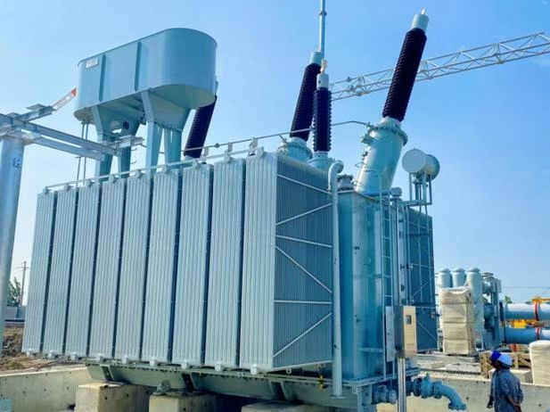
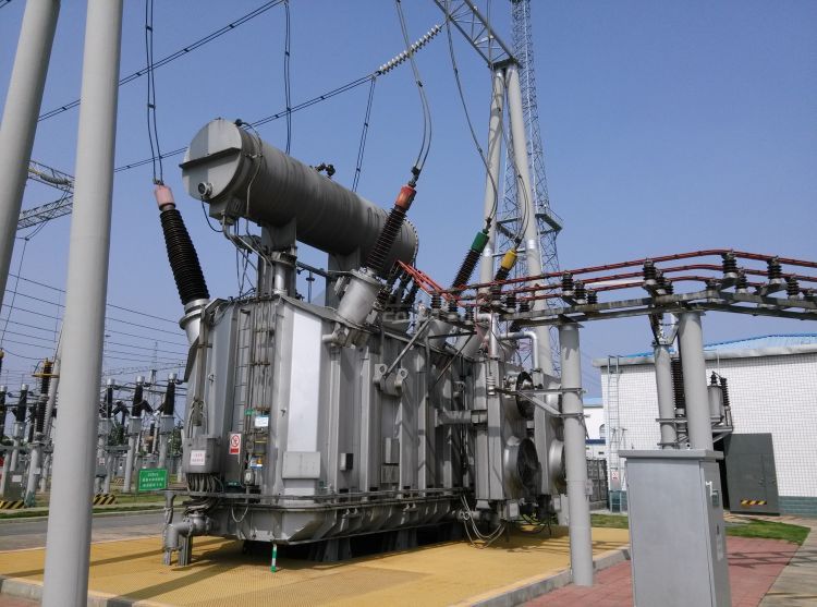
A power transformer is a static electrical device used in high-voltage transmission networks to transfer electrical energy between circuits by electromagnetic induction. It operates on the principle of mutual induction between windings, allowing it to step up (increase) or step down (decrease) voltage levels with minimal energy loss. Power transformers consist of a core, primary and secondary windings, insulating materials, and a cooling and protective enclosure, and are primarily used at substations to link different voltage levels in generation, transmission, and distribution systems.
This article explains the construction, function, and real-world application of power transformers in a modern energy system—from their physics to practical deployment.
Power transformers operate based on electromagnetic induction and are used to change voltage levels in high-voltage networks.True
By transferring energy through magnetic coupling, power transformers enable efficient transmission and voltage matching across the grid.
Power transformers use rotating mechanical parts to transform voltage levels.False
Power transformers are static devices with no moving parts; they rely entirely on electromagnetic principles.
1. What Is a Power Transformer?
A power transformer is a static device that transfers electrical energy between two or more circuits through electromagnetic induction, typically between generators, substations, and load centers. It is optimized for high-voltage, high-power applications, typically operating in the 100 kVA to 1000 MVA range at voltages from 33 kV up to 765 kV or more.
2. How Does a Power Transformer Work?
Fundamental Principle: Mutual Induction
| Component | Function |
|---|---|
| Primary winding | Receives input voltage |
| Secondary winding | Delivers transformed voltage |
| Magnetic core | Carries alternating magnetic flux |
| Flux linkage | Couples the windings through the core |
$$\text{EMF}_{\text{secondary}} = N_s \cdot \frac{d\Phi}{dt}$$
$$\frac{V_s}{V_p} = \frac{N_s}{N_p}$$
- $V_s$, $V_p$: Secondary and primary voltages
- $N_s$, $N_p$: Turns in secondary and primary windings
- $\Phi$: Magnetic flux in the core
Voltage transformation ratio depends on the turns ratio of the windings.
3. Core Components and Structure
| Component | Description |
|---|---|
| Laminated magnetic core | Low-loss silicon steel sheets that guide flux |
| Primary and secondary coils | Copper or aluminum windings wound around core limbs |
| Tank and bushings | Metal casing filled with insulating oil, with high-voltage terminals |
| Cooling system | Radiators, fans, or pumps to remove heat |
| Insulation | Oil, paper, pressboard materials to separate conductors |
Larger power transformers may also include on-load tap changers (OLTCs) for voltage regulation.
4. Types of Power Transformers
| Type | Application |
|---|---|
| Step-up transformer | Raises voltage at generation plant (e.g., 11 kV to 400 kV) |
| Step-down transformer | Lowers voltage at substation (e.g., 400 kV to 33 kV) |
| Auto-transformer | Uses shared windings for compactness and efficiency |
| Three-phase transformer | Standard for grid applications in 3-phase AC systems |
| HVDC transformer | Used in high-voltage DC transmission links (with converters) |
5. Efficiency and Losses
| Loss Type | Description | Typical Range |
|---|---|---|
| Core loss (no-load) | Due to hysteresis and eddy currents in the core | 0.1%–0.3% of rated power |
| Copper loss (load) | $I^2R$ losses in windings under load | 0.5%–1.5% of rated power |
Power transformers are highly efficient: 98%–99.5% under nominal conditions. They include cooling systems, shielding, and core optimization to minimize energy loss.
6. Applications of Power Transformers
| Sector | Role of Power Transformer |
|---|---|
| Generation plants | Step up voltage for long-distance transmission |
| Transmission networks | Interconnect regional or national grids |
| Substations | Step down voltage for distribution transformers |
| Industrial facilities | Feed high-voltage equipment and motors |
| Renewable energy | Integrate wind farms and solar plants into the grid |
7. Cooling Methods
| Cooling Method | Description |
|---|---|
| ONAN (Oil Natural Air Natural) | Passive cooling using oil and air convection |
| ONAF (Oil Natural Air Forced) | Fans increase air cooling rate |
| OFWF (Oil Forced Water Forced) | Pumps circulate oil and water in heat exchanger |
Cooling prevents thermal stress, oil breakdown, and hotspot formation inside the transformer.
8. Safety and Protection Features
| Protection Element | Function |
|---|---|
| Buchholz relay | Detects gas accumulation (internal faults) |
| Differential relay | Identifies winding faults or short circuits |
| Temperature sensors | Monitor oil and winding heat buildup |
| Pressure relief device | Vents gases to prevent tank rupture |
These protections ensure safe operation under fault, overload, or abnormal conditions.
9. Power Transformer Ratings (Examples)
| Rating (MVA) | Voltage (kV) | Application |
|---|---|---|
| 50 MVA | 220/33 kV | Transmission substation |
| 100 MVA | 400/132 kV | Regional interconnection |
| 500 MVA | 765/400 kV | Ultra-high voltage transmission |
Ratings are based on apparent power (MVA), voltage ratio, frequency, cooling class, and impedance.
Why Is Voltage Transformation Necessary in Power Systems?
If you’ve ever wondered why electricity travels over high-voltage lines only to be stepped down before reaching your home or business, the answer lies in one of the most essential principles of modern power systems: voltage transformation. Without it, long-distance transmission would be inefficient, dangerous, and economically unfeasible. Voltage transformation enables electricity to be transmitted with minimal losses, optimized cost, and equipment compatibility—making it the invisible backbone of power delivery infrastructure.
Voltage transformation is necessary in power systems to reduce transmission losses, ensure safe and efficient long-distance energy transport, match voltage levels between generation and consumption points, support system reliability, and optimize equipment design and cost. Transformers enable this by stepping up voltage for transmission and stepping it down for distribution and end use.
This article explains why voltage transformation is critical, how it works, and the system-wide benefits it provides.
Voltage transformation reduces transmission losses and allows efficient, safe power delivery over long distances.True
Higher voltages reduce current for the same power, which minimizes I²R losses in conductors.
Electricity can be transmitted at low voltage over long distances without issue.False
Transmitting electricity at low voltage would require massive conductors, cause high energy loss, and be economically impractical.
1. Fundamental Principle: Power = Voltage × Current
To understand the need for voltage transformation, consider the basic power formula:
$$P = V \times I$$
- For a fixed power demand, increasing voltage decreases current.
- Electrical losses in wires are given by:
$$\text{Power loss} = I^2 \times R$$
Lower current = less heat loss in transmission lines.
2. High Voltage = Lower Losses
| Voltage Level | Transmission Distance (km) | Power Losses (%) |
|---|---|---|
| 11 kV | < 10 | \~8–12% |
| 132 kV | 50–150 | \~2–4% |
| 400 kV | 500+ | <2% |
- Power plants generate electricity at low to medium voltages (11–33 kV).
- Step-up transformers raise this to 132–765 kV for transmission.
- At the consumption end, step-down transformers reduce voltage to 33 kV, 11 kV, or 400 V depending on the load.
This multi-level voltage transformation ensures power travels efficiently and safely.
3. Reasons Voltage Transformation Is Necessary
| Purpose | Explanation |
|---|---|
| Reduce I²R losses | Higher voltage reduces current, minimizing heat loss in lines |
| Minimize conductor size | Lower current allows use of smaller, cost-effective conductors |
| Improve transmission efficiency | Less loss = more power delivered to consumers |
| Equipment protection | Ensures voltage levels match device ratings at substations and homes |
| Support grid interconnectivity | Different grids or systems operate at varying voltages |
| Enable bulk power transfer | Moves hundreds of MW over long distances with manageable infrastructure |
4. Real-World Example: Without Voltage Transformation
Scenario:
- Power station generates 100 MW at 11 kV
- Transmission line resistance: 1 ohm/km
- Distance: 100 km
Without step-up (11 kV):
- Current = $I = P/V = 100,000 kW / 11 kV ≈ 9,090 A$
- Loss = $I^2 \cdot R = (9,090)^2 \cdot 100 = 8.3 \text{ MW lost}$
With step-up to 220 kV:
- Current = $100,000 kW / 220 kV = 454 A$
- Loss = $(454)^2 \cdot 100 = 2.1 \text{ MW lost}$
Voltage transformation reduces energy loss by nearly 75% in this case.
5. Voltage Transformation in the Power System Hierarchy
| Power System Stage | Typical Voltage Level | Function |
|---|---|---|
| Generation | 11–33 kV | Produced by alternators |
| Step-up Transformer | 132–765 kV | Raises voltage for transmission |
| Transmission | 132–765 kV | Long-distance high-power transport |
| Step-down Transformer | 33–132 kV | Prepares for regional distribution |
| Distribution | 11–33 kV | Medium-distance to city substations |
| Local Delivery | 400 V / 230 V | Final delivery to homes and offices |
6. Economic and Environmental Benefits
| Benefit | Impact |
|---|---|
| Lower losses | Reduces CO₂ emissions from power waste |
| Smaller cables and towers | Saves material and land costs |
| Longer transmission distances | Enables centralized and renewable generation |
| Flexible interconnection | Facilitates regional grid balancing |
High-voltage systems make nationwide and even cross-border power networks possible.
7. Voltage and Transformer Efficiency
| Voltage Level | Transformer Type | Typical Efficiency (%) |
|---|---|---|
| Low (11–33 kV) | Distribution transformer | 96–98% |
| Medium (66–132 kV) | Sub-transmission unit | 97–98.5% |
| High (220–765 kV) | Power transformer | 98.5–99.5% |
Power transformers are engineered for minimal loss due to the high energy they handle.
Summary Table: Why Voltage Transformation Is Critical
| Function | Why It's Needed |
|---|---|
| Reduce line losses | Less current = less heat (I²R) |
| Optimize infrastructure cost | Smaller conductors, shorter towers |
| Match equipment ratings | Protect appliances, grid assets |
| Enable long-distance power flow | Make remote generation viable |
| Increase system stability | Regulate voltage across network |
| Lower environmental impact | Less energy loss = lower emissions |
Where Are Power Transformers Typically Used?
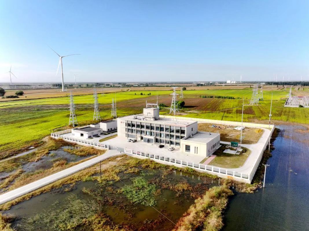
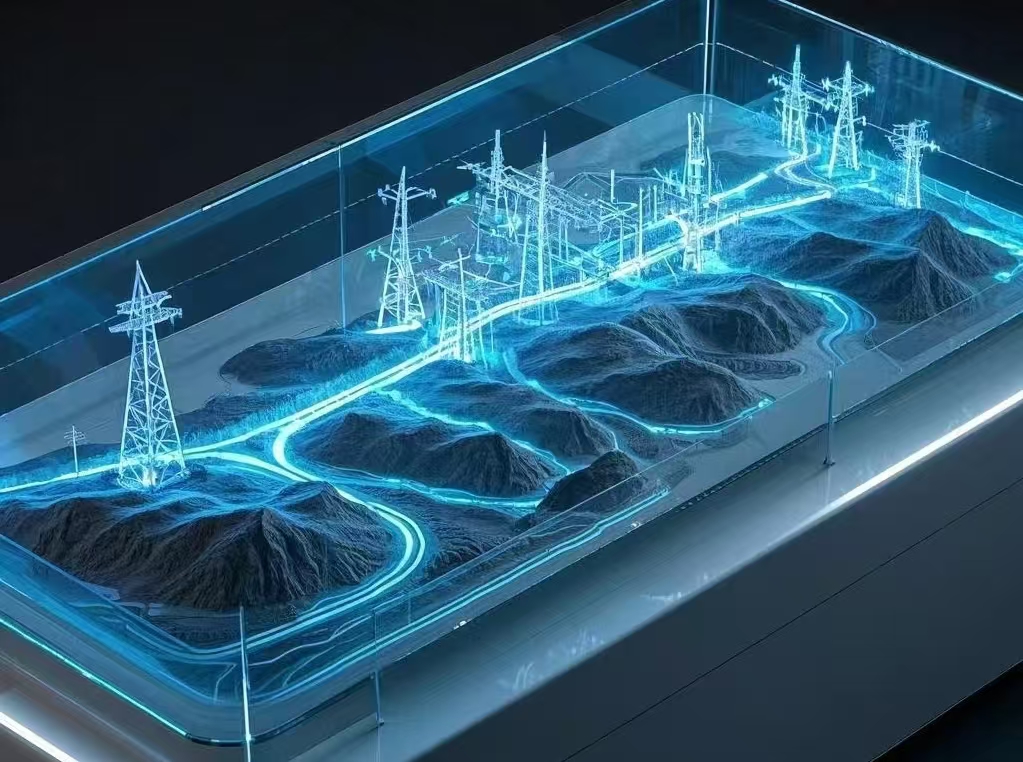
Power transformers are the backbone of modern power infrastructure, designed to handle high voltages and massive energy flows across national and regional grids. While they’re most visible in large substations, their applications span far beyond transmission—they are found wherever voltage must be stepped up or down for efficient and reliable delivery of electrical power. Their strategic placement throughout the system enables low-loss transmission, grid stability, and system interoperability from generation to consumption.
Power transformers are typically used in high-voltage applications such as generation switchyards, transmission substations, interconnection points between regional grids, industrial plants, renewable energy farms, and infrastructure for large commercial loads. They enable voltage transformation for bulk power transfer, reduce losses over long distances, and allow the grid to function as a coordinated and scalable energy delivery system.
This article outlines the main environments and scenarios where power transformers are installed—and how they function in each context.
Power transformers are used in high-voltage generation, transmission, and industrial networks to transfer energy efficiently across different voltage levels.True
Their ability to handle large voltages and currents makes them essential at substations, power plants, and major grid interfaces.
Power transformers are mainly used in homes and small buildings.False
Homes use distribution transformers, not power transformers, which are designed for high-voltage, high-capacity grid applications.
1. Generation Switchyards (Power Plants)
| Location | Voltage Role |
|---|---|
| Thermal, hydro, and nuclear plants | Step-up from 11–33 kV to 132–765 kV for transmission |
Function:
- Connects generator output to transmission grid
- Matches low generator voltage with high-voltage lines
- Reduces transmission losses from source
Example:
A 600 MVA, 400/22 kV power transformer in a hydroelectric station steps up voltage for long-distance grid transport.
2. Transmission Substations
| Location | Voltage Role |
|---|---|
| Grid transmission node | Step-down from 400/220/132 kV to sub-transmission levels (e.g., 66 or 33 kV) |
Function:
- Connects different voltage levels across the grid
- Acts as a bridge between ultra-high voltage and regional systems
- Supports load centers, cities, and inter-state exchanges
Features:
- Equipped with OLTCs, surge arresters, Buchholz protection
- High short-circuit withstand capacity
3. Grid Interconnection Points
| Use Case | Function |
|---|---|
| Inter-regional or international tie-lines | Align different voltage/frequency standards |
Function:
- Balances load between neighboring grids
- Ensures synchronization and protection coordination
- Used in HVDC back-to-back systems and AC interconnects
Example:
Auto-transformers at a 765/400 kV station handling power exchange between two national grids.
4. Heavy Industrial Complexes
| Industry Type | Transformer Application |
|---|---|
| Steel, aluminum, cement plants | Step-down high-voltage power for heavy equipment (e.g., 220/33 kV) |
Function:
- Provides stable, high-capacity power to motors, furnaces, and conveyor systems
- Withstands fluctuating loads and harmonics
- Often customized for harmonic filtering and fault protection
Industrial transformers must tolerate non-linear loads, transient spikes, and rugged operating conditions.
5. Renewable Energy Farms (Wind & Solar)
| Location | Voltage Role |
|---|---|
| Wind turbine clusters or solar PV farms | Step-up from 0.6–33 kV to 66–220 kV for grid export |
Function:
- Aggregates renewable generation into grid-compatible voltage
- Interfaces with transmission or sub-transmission substations
- May include inverter transformers or collector step-up units
Features:
- Enhanced cooling for desert/sun-rich zones
- Insulation adapted for harmonic-rich environments
6. Urban and Regional Distribution Hubs
| Location | Role in Distribution System |
|---|---|
| Major city substations | Step-down from 220/132 kV to 66/33/11 kV |
Function:
- Supplies power to urban feeders, hospitals, transportation, and data centers
- Connects with distribution transformers at feeder terminals
- Enables automated load balancing and smart grid control
7. Infrastructure and Utility-Scale Facilities
| Facility Type | Use Case |
|---|---|
| Airports, military bases, data centers | On-site power supply at specific voltage requirements |
Function:
- Dedicated power transformers feed mission-critical infrastructure
- Supports microgrid or islanding capability during grid disturbances
Features:
- Often equipped with redundant units, intelligent monitoring, and advanced protection
Summary Table: Common Applications of Power Transformers
| Application Area | Typical Voltage Levels | Purpose |
|---|---|---|
| Generation switchyards | 11–33 kV → 220–765 kV | Step-up for transmission |
| Transmission substations | 765/400/220/132 kV | Step-down for sub-transmission |
| Grid interconnects | 765 ↔ 400 kV / HVDC interfaces | Synchronize regions, transfer bulk power |
| Industrial plants | 220/132 → 33/11 kV | Power intensive machinery and systems |
| Renewable farms | 0.6–33 → 132/220 kV | Grid integration of green energy |
| Urban substations | 220/132 → 33/11 kV | Power distribution to cities and districts |
| Infrastructure hubs | Custom voltage (e.g., 132/66/33) | Site-specific critical power delivery |
What Is the Difference Between Step-Up and Step-Down Transformers?
Transformers are fundamental to modern electrical systems, but not all transformers serve the same purpose. The key distinction lies in their voltage transformation direction. Whether delivering high-voltage electricity from a generation station or preparing it for safe residential use, understanding the roles of step-up and step-down transformers is crucial for electrical engineers, power planners, and system operators.
The main difference between step-up and step-down transformers lies in their voltage transformation function: a step-up transformer increases voltage from low to high to enable efficient power transmission, while a step-down transformer decreases voltage from high to low to make electricity safe for distribution and usage. The difference is achieved through the turns ratio of the transformer windings—more turns on the secondary coil for step-up, and more turns on the primary coil for step-down.
This article explores the structural, functional, and application-based differences between step-up and step-down transformers, helping you determine where and why each type is used.
Step-up transformers increase voltage for transmission, while step-down transformers reduce voltage for distribution and usage.True
Step-up units raise voltage to reduce losses over distance, and step-down units ensure electricity is safe and usable at homes and businesses.
Step-up and step-down transformers operate identically with no design or functional difference.False
While both rely on electromagnetic induction, their winding configurations and roles in the grid are functionally opposite.
1. Basic Working Principle (Same for Both)
All transformers operate on the principle of electromagnetic induction:
$$\frac{V_s}{V_p} = \frac{N_s}{N_p}$$
- $V_s$ = Secondary voltage
- $V_p$ = Primary voltage
- $N_s$ = Number of secondary winding turns
- $N_p$ = Number of primary winding turns
The ratio of the number of coil turns determines whether the transformer steps voltage up or down.
2. Step-Up Transformer
| Characteristic | Description |
|---|---|
| Function | Increases voltage from a lower to a higher level |
| Winding configuration | Secondary winding has more turns than primary |
| Typical location | Power generation plants |
| Input voltage | 11 kV–33 kV (from generator) |
| Output voltage | 132 kV–765 kV (for transmission) |
| Key benefit | Reduces current to minimize I²R transmission losses |
Example:
A 22/400 kV step-up transformer increases the generator output voltage for efficient grid transmission.
3. Step-Down Transformer
| Characteristic | Description |
|---|---|
| Function | Decreases voltage from a higher to a lower level |
| Winding configuration | Primary winding has more turns than secondary |
| Typical location | Substations, distribution points, and service entrances |
| Input voltage | 132–400 kV (transmission voltage) |
| Output voltage | 11–33 kV (distribution) or 400 V (residential) |
| Key benefit | Makes voltage levels safe and usable for end users |
Example:
A 132/33 kV step-down transformer reduces transmission voltage for regional distribution feeders.
4. Key Structural and Design Differences
| Parameter | Step-Up Transformer | Step-Down Transformer |
|---|---|---|
| Coil size (physically) | Secondary coil is thicker and has more turns | Primary coil is thicker and has more turns |
| Insulation requirement | Higher on secondary side | Higher on primary side |
| Voltage stress management | Designed for high-voltage output | Designed for high-voltage input |
Both types may use similar core materials, tank design, and protection systems—but with different insulation grading and winding configurations.
5. Applications of Step-Up vs. Step-Down Transformers
| Application Sector | Step-Up Transformers | Step-Down Transformers |
|---|---|---|
| Generation Stations | Raise voltage to enter transmission grid | — |
| Transmission Substations | Occasionally used between HV levels | Lower voltage for local grid distribution |
| Renewable Plants | Raise voltage from inverter/collector units | — |
| Industrial Loads | — | Power heavy motors or furnaces from 33 or 11 kV |
| Commercial/Residential | — | Feed service voltage at 400/230 V |
6. Comparison Table: Step-Up vs. Step-Down Transformers
| Feature | Step-Up Transformer | Step-Down Transformer |
|---|---|---|
| Voltage transformation | Low → High | High → Low |
| Use location | Generation side | Distribution side |
| Turns ratio (Nₛ/Nₚ) | Greater than 1 | Less than 1 |
| Current behavior | Output current < input current | Output current > input current |
| Cooling demand | Often higher due to higher voltage | Higher load current = more heat |
| Common rating examples | 22/220 kV, 33/400 kV | 132/33 kV, 33/0.4 kV |
7. Shared Features Despite Differences
| Shared Component | Function |
|---|---|
| Core (CRGO steel or amorphous) | Guides magnetic flux |
| Tank and oil system | Cools and insulates |
| Bushing terminals | Interface with HV and LV lines |
| Buchholz relay | Detects internal gas formation |
| Tap changers (in some cases) | Adjusts voltage ratio under load |
Though their purpose differs, both transformer types are engineered for high reliability, safety, and thermal performance.
How Do Power Transformers Support Grid Stability?
In modern power systems, grid stability is everything. A momentary voltage sag, frequency deviation, or overload can trigger widespread blackouts or damage sensitive equipment. Amid fluctuating demand, renewable integration, and inter-regional transmission, power transformers play a critical stabilizing role. These high-voltage machines are not just passive voltage changers—they actively support the balance, control, and security of the entire grid.
Power transformers support grid stability by enabling voltage regulation, balancing power flow between regions, reducing losses during transmission, isolating faulted sections, maintaining frequency control through reactive power management, and supporting the integration of renewable energy sources. Their design and deployment allow grids to maintain continuity, reliability, and dynamic equilibrium during normal and abnormal conditions.
This article breaks down how power transformers contribute to a stable grid, both under routine operation and in response to disturbances or faults.
Power transformers contribute to grid stability by managing voltage, power flow, and fault isolation.True
Their ability to transform voltage levels and connect regions helps balance load, minimize loss, and prevent cascading failures.
Power transformers have no effect on grid stability.False
In fact, transformers are essential to voltage control, system isolation, and reliable power delivery, all of which affect grid stability.
1. Voltage Regulation and Control
| Function | Impact on Grid Stability |
|---|---|
| Adjusts voltage levels | Maintains nominal voltage at all grid points |
| Includes OLTC (On-load tap changer) | Continuously regulates voltage under load |
How:
- OLTCs in power transformers vary winding tap positions during operation to adjust the output voltage in real-time.
- Helps stabilize voltage fluctuations from load changes or renewable input.
Stable voltage prevents overheating, equipment damage, and power quality issues across the grid.
2. Balancing Inter-Regional Power Flow
| Scenario | Transformer Role |
|---|---|
| Excess power in Region A | Transformer steps down or up voltage to match transfer needs |
| Deficit in Region B | Transformer balances inflow to restore demand |
Applications:
- Auto-transformers and inter-bus transformers help tie together grid regions operating at different voltages (e.g., 400 kV to 220 kV).
- They help reroute power to balance supply and demand across zones.
Balancing power between regions reduces the risk of localized overloads and cascading failures.
3. Reactive Power and Frequency Stability
| Role | Transformer Behavior |
|---|---|
| Voltage-dependent reactive power | Inductive or capacitive characteristics of windings affect system voltage |
| Magnetizing current control | Helps in stabilizing frequency indirectly by maintaining correct flux balance |
Impact:
- Helps maintain voltage stability in the presence of inductive or capacitive loads.
- Aids in synchronous stability during grid disturbances by supporting reactive demand.
Without transformer support, frequency deviation and voltage collapse are more likely during peak load or fault recovery.
4. Fault Isolation and System Protection
| Transformer Feature | Stability Contribution |
|---|---|
| High-impedance design | Limits fault current propagation |
| Differential protection relays | Detect internal winding faults and isolate units |
| Buchholz relay (gas protection) | Detects slow-developing internal faults |
Use Case:
- During a fault in one section, transformers isolate the issue and prevent it from propagating across regions.
- This minimizes the impact radius, allowing healthy parts of the grid to operate unaffected.
5. Support for Grid Restoration (Black Start)
| Black Start Role | Transformer’s Function |
|---|---|
| After a full grid outage | Enables reconnection of zones in controlled manner |
| During system ramp-up | Gradually transforms voltage to safe operating levels |
In black start scenarios, transformers re-energize the grid one section at a time, avoiding large inrushes or instabilities.
6. Facilitating Renewable Integration
| Challenge | Transformer Contribution |
|---|---|
| Intermittent output from renewables | Transformers stabilize voltage at grid entry points |
| Variable solar/wind input | Step-up transformers at PV/wind plants match voltage with grid |
Example:
- A 33/132 kV step-up transformer at a solar farm helps feed consistent voltage into the grid despite fluctuating PV output.
Transformers act as interfaces between variable renewable sources and stable grid backbones.
7. Reducing Transmission Losses
| Transformer Action | Grid Benefit |
|---|---|
| Stepping up voltage | Reduces line current and I²R losses |
| Improves power transfer efficiency | Ensures more energy reaches end users |
Consequence:
- Lower transmission losses = less thermal stress, better system balance, and improved grid efficiency.
8. Stability During Load Shedding or Switching
| Situation | Transformer Support |
|---|---|
| Sudden load drop | OLTCs adjust voltage to avoid overvoltage |
| High load addition | Manages inrush and minimizes voltage sag |
Feature:
- Proper transformer impedance and tap changer delay coordination smooth out switching impacts on the grid.
These features help the grid absorb shocks and adjust dynamically to changing load conditions.
Summary Table: How Power Transformers Support Grid Stability
| Function | Stability Benefit |
|---|---|
| Voltage transformation | Maintains correct levels across regions |
| Tap changer control (OLTC) | Real-time voltage regulation |
| Power flow balancing | Redistributes load to prevent overloads |
| Fault isolation | Limits propagation of disturbances |
| Reactive power influence | Supports voltage and frequency stabilization |
| Integration of renewables | Smooths intermittent energy sources |
| Support for black start | Enables phased reconnection post-outage |
| Loss minimization | Reduces thermal load and stabilizes line performance |
What Safety and Efficiency Features Are Integrated in Power Transformers?
Power transformers operate at extremely high voltages and currents, making them both critical and potentially dangerous components of the electrical grid. To ensure safe, efficient, and continuous operation, these transformers are equipped with a wide range of built-in safety protections and performance-enhancing features. Whether guarding against internal faults, managing overloads, or reducing energy losses, these features help prevent failures, optimize efficiency, and extend operational life.
Power transformers include a range of safety and efficiency features such as Buchholz relays, oil and winding temperature sensors, surge arresters, gas detection systems, pressure relief devices, high-efficiency core materials, OLTCs (On-load Tap Changers), advanced cooling systems, and online monitoring tools. These features work together to protect the transformer from faults, reduce energy losses, and ensure stable performance.
This article explores the integrated technologies in power transformers that enhance both their safety in operation and efficiency in energy conversion.
Power transformers are equipped with safety features like Buchholz relays, pressure relief valves, and temperature sensors to detect and prevent internal faults.True
These devices act as early warning systems and shutdown triggers to prevent catastrophic failure.
Efficiency and safety in power transformers are enhanced through optimized cores, advanced cooling, and monitoring systems.True
Features like CRGO steel, ONAF cooling, and SCADA-linked diagnostics reduce losses and support predictive maintenance.
1. Buchholz Relay (Gas Detection Safety)
| Feature | Function |
|---|---|
| Gas detection chamber | Senses gases generated by internal faults |
| Float switches | Triggers alarm or trip circuit |
Safety Role:
- Detects slow-developing internal arcing or insulation failure
- First line of defense for oil-immersed transformers
Operation:
- Mounted between main tank and conservator
- Trips circuit breaker if gas accumulation reaches critical level
Buchholz relays are mandatory in most power-grade transformers above 500 kVA.
2. Oil and Winding Temperature Monitoring
| Sensor Type | Purpose |
|---|---|
| Top oil thermometer | Tracks thermal conditions of the cooling medium |
| Winding hot-spot detector | Identifies dangerous internal heat buildup |
Efficiency and Protection:
- Prevents overheating that leads to insulation degradation
- Temperature alarms or trips prevent thermal runaway
Integration:
- Connected to SCADA or local RTUs for real-time alerts
- Supports dynamic loading decisions under peak conditions
3. Pressure Relief Device (PRD)
| Function | Grid Safety Application |
|---|---|
| Releases internal pressure | Prevents tank rupture during gas buildup |
| Automatic self-reset | Ready after pressure returns to normal |
Installation:
- Mounted on tank cover or side
- Linked with trip circuit in fault-critical designs
Prevents explosion or fire risk in the event of dielectric breakdown or arc flash.
4. Surge Arresters and Lightning Protection
| Device | Role in Voltage Spike Protection |
|---|---|
| Metal oxide varistor (MOV) | Diverts lightning surge energy to ground |
| Surge counter | Logs number of discharge events |
Application:
- Installed on HV bushings or incoming lines
- Essential for grids in lightning-prone or mountainous regions
Prevents dielectric flashover from external overvoltages.
5. Cooling Systems (Efficiency and Thermal Safety)
| Cooling Type | Description | Efficiency Impact |
|---|---|---|
| ONAN | Oil Natural Air Natural | Basic passive cooling |
| ONAF | Oil Natural Air Forced (fans) | Enhances cooling during high load |
| OFWF | Oil Forced Water Forced | Used in very high-capacity transformers |
Features:
- Thermostatically controlled fans/pumps
- Reduces core and copper losses via temperature control
- Helps keep load cycling within design limits
Efficient cooling contributes to lower operating costs and longer insulation life.
6. On-Load Tap Changer (OLTC)
| Device Function | Voltage Regulation Role |
|---|---|
| Adjusts transformer turns ratio | Maintains constant output voltage under load |
| Motor-driven selector switch | Moves taps without interrupting power flow |
Efficiency Benefits:
- Allows dynamic voltage control
- Compensates for line drops and load imbalances
- Reduces reactive power burden
Safety Add-on:
- Tap change monitors to detect contact wear or arcing
- Oil filtration unit for diverter switch protection
7. High-Efficiency Core and Winding Materials
| Material | Function |
|---|---|
| CRGO (Cold Rolled Grain Oriented) steel | Reduces core losses and magnetic hysteresis |
| Copper or aluminum windings | Optimized for lower resistance and thermal loss |
Efficiency Features:
- Core losses kept to <0.25% of rated power
- Winding designs minimize eddy currents and skin effect
Material choices significantly improve efficiency (up to 99.5%) and reduce carbon footprint.
8. Oil Level Indicators and Moisture Sensors
| Monitoring Device | Fault Prevention Role |
|---|---|
| Oil level gauge | Prevents dry operation and alerts for leaks |
| Silica gel breather indicator | Signals moisture saturation |
| Online moisture sensors | Detect in-tank humidity for insulation safety |
Application:
- Protects against oil leaks, moisture ingress, and dielectric weakening
9. Grounding and Earth Fault Detection
| Safety Element | Grid Protection Function |
|---|---|
| Solid grounding of tank/frame | Discharges stray currents and fault energy safely |
| Restricted Earth Fault (REF) relay | Triggers alarm/trip on bushing-to-ground fault |
Reduces shock hazards, fire risk, and system imbalance.
10. Digital Monitoring and SCADA Integration
| Monitoring Parameter | Real-Time Alert Capability |
|---|---|
| Oil/winding temperature | Auto trip if limit exceeded |
| Tap position tracking | Remote fault logging and voltage optimization |
| Partial discharge activity | Early insulation fault detection |
| Gas level (DGA) and pressure | Predictive maintenance alerts |
Platforms:
- Smart transformer systems use IEC 61850, Modbus, or cloud-based analytics
- Enables condition-based maintenance and fault prediction
Summary Table: Key Safety and Efficiency Features in Power Transformers
| Feature | Category | Benefit |
|---|---|---|
| Buchholz relay | Safety | Detects internal arc/gas faults |
| Temperature sensors | Both | Prevents overheating, enables load planning |
| Surge arresters | Safety | Protects against lightning/switching surges |
| OLTC | Efficiency | Maintains voltage stability under load |
| Efficient core materials | Efficiency | Reduces no-load losses |
| Pressure relief devices | Safety | Prevents tank rupture during fault |
| Cooling systems | Both | Manages thermal stress, extends life |
| Moisture/oil level sensors | Safety | Prevents dielectric breakdown |
| Digital monitoring systems | Both | Enables predictive maintenance and control |
Conclusion
The purpose of a power transformer extends beyond just changing voltage—it plays a pivotal role in the safe, efficient, and reliable operation of the entire power grid. From ensuring minimal transmission losses to adapting electricity for industrial or residential use, power transformers are indispensable in every stage of the power supply chain. Understanding their function is fundamental to grasping how electricity powers our modern world.
FAQ
Q1: What is the main purpose of a power transformer?
A1: The primary purpose of a power transformer is to transfer electrical energy between two or more circuits at different voltage levels. It enables the stepping up of voltage for transmission over long distances and the stepping down of voltage for safe distribution to homes and industries.
Q2: How does a power transformer support electrical power transmission?
A2: Power transformers step up the voltage at generating stations to high levels (e.g., 110 kV or more) for long-distance transmission, which reduces current and minimizes energy losses. At the receiving end, another transformer steps the voltage down to usable levels.
Q3: Why is voltage transformation important in power systems?
A3: Voltage transformation helps:
Reduce power loss over transmission lines
Improve transmission efficiency
Ensure safe and compatible voltage levels for different applications
Enable grid integration of power from multiple sources
Q4: Where are power transformers typically used?
A4: Power transformers are used in:
Power generation stations
High-voltage transmission substations
Industrial complexes
Renewable energy installations (e.g., wind farms, solar plants)
They form the backbone of the electrical grid.
Q5: What are the key characteristics of power transformers?
A5: Power transformers are designed for:
High voltage and current handling
High efficiency
Continuous operation
Durability and reliability under varying load conditions
They often include cooling systems, protective relays, and monitoring sensors.
References
"Understanding the Purpose of Power Transformers" – https://www.transformertech.com/purpose-of-power-transformers – Transformer Tech
"Why Power Transformers Are Essential for Transmission" – https://www.powermag.com/power-transformer-purpose – Power Magazine
"Functions and Importance of Power Transformers" – https://www.electrical4u.com/power-transformer-function – Electrical4U
"Role of Power Transformers in Electrical Systems" – https://www.sciencedirect.com/power-transformer-role – ScienceDirect
"Power Transformer Basics and Applications" – https://www.researchgate.net/power-transformer-applications – ResearchGate
"Smart Grid Integration with Power Transformers" – https://www.smartgridnews.com/power-transformers-grid – Smart Grid News
"Energy Central: Power Transformer Fundamentals" – https://www.energycentral.com/c/ee/purpose-of-transformers – Energy Central
"PowerGrid Overview of High-Voltage Transformers" – https://www.powergrid.com/high-voltage-transformers – PowerGrid