While transformers are widely known for adjusting voltage levels in power systems, they also serve several specialized purposes beyond standard power transmission. These special applications make transformers indispensable in fields like electronics, industry, medical systems, and renewable energy. This article explores the special purposes that go beyond basic voltage transformation.
What Are Instrument Transformers Used For?
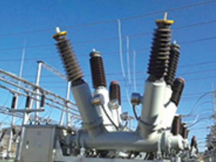
In high-voltage and medium-voltage systems, direct measurement of current and voltage is not only impractical—it’s dangerous. Without the ability to safely and accurately monitor power system parameters, grid control, protection, and metering would be impossible. That’s where instrument transformers come in. These compact devices step down high currents or voltages to safe, measurable levels, enabling precise control, monitoring, and protection of electrical systems without exposing personnel or equipment to high energy levels. In this article, we’ll explain what instrument transformers are used for, their types, roles, and why they are essential in every electrical substation, industrial switchgear, and commercial power panel.
Instrument transformers are used to convert high voltages and high currents into proportional, low-voltage and low-current signals for measurement, monitoring, metering, and protection. They allow instruments like energy meters, protection relays, and control devices to operate safely and accurately in high-voltage environments. The two main types are current transformers (CTs) and voltage transformers (VTs or PTs).
From utility substations to building switchboards, these specialized transformers play a critical but silent role in keeping systems safe, accurate, and controllable.
Instrument transformers reduce high voltages or currents to safe, measurable values for meters and relays.True
They are designed to provide isolated and proportional output signals used in monitoring, protection, and metering circuits.
Instrument transformers are used to supply power to homes and buildings.False
Instrument transformers do not supply power; they are used for measurement and protection purposes only.
Main Functions of Instrument Transformers
| Function | Explanation |
|---|---|
| Measurement | Provide accurate, scaled signals to voltmeters, ammeters, and energy meters |
| Protection | Feed protection relays with real-time voltage or current data for trip decisions |
| Isolation | Electrically separate high-energy circuits from sensitive control equipment |
| Standardization | Normalize outputs (e.g., 1 A, 5 A, 110 V) for relay compatibility and calibration |
| Monitoring & Automation | Enable SCADA, fault logging, and load analysis |
These transformers allow continuous observation of power system health and immediate response to faults.
Types of Instrument Transformers
| Type | Primary Function | Common Voltage/Current Range | Typical Output |
|---|---|---|---|
| Current Transformer (CT) | Measures current by stepping it down | 10 A to 30,000 A | 1 A or 5 A |
| Voltage Transformer (VT/PT) | Measures voltage by stepping it down | 3.3 kV to 765 kV | 110 V or 100 V |
| Combined CT/VT | Provides both functions in compact form | 11 kV – 33 kV substations | Dual outputs |
CTs and VTs are often paired together to provide complete electrical visibility for relays and metering panels.
Real-World Applications by Use Case
| Use Case | Instrument Transformer Role |
|---|---|
| Substations | Feed protection relays and meters to monitor incoming/outgoing feeders |
| Switchgear Panels | Provide inputs to digital multifunction relays |
| Energy Billing (Utilities) | Feed revenue-grade meters with accurate current and voltage inputs |
| Industrial Plants | Monitor motor loads and detect phase unbalance or overloads |
| Grid Automation (SCADA) | Enable data acquisition and remote fault response |
| High-Speed Protection Systems | Feed differential, distance, and overcurrent protection relays |
Accuracy Classes and Standardization
| Application | Accuracy Class for CTs | Accuracy Class for VTs |
|---|---|---|
| Protection Relays | 5P, 10P (up to 10% error) | 3P or 6P |
| Revenue Metering | 0.2S, 0.5S (very high accuracy) | 0.2, 0.5 |
| General Monitoring | 1.0, 3.0 | 1.0 |
The “P” class is for protection, “S” class for high-accuracy metering, ensuring that devices receive data within strict tolerances.
Internal Construction and Working
Current Transformer (CT):
- Primary winding: Often a single conductor or busbar
- Magnetic core: Encircles the primary to induce current in the secondary
- Secondary winding: Delivers scaled current to the relay or meter
Voltage Transformer (VT/PT):
- Primary winding: Connected across a phase or line
- Secondary winding: Outputs safe low voltage
- Electromagnetic insulation: Provides safe isolation
Both are built to withstand insulation levels of the system they monitor (e.g., 11 kV, 33 kV, 132 kV, etc.).
Instrument Transformer Selection Considerations
| Parameter | Impact on Performance |
|---|---|
| Burden (VA rating) | Must match the load of connected devices (meters, relays) |
| Accuracy class | Depends on whether used for protection or billing |
| Insulation level | Must match system voltage and withstand surges |
| Ratio (primary\:secondary) | Determines scaling and compatibility with instruments |
| Mounting type | Indoor (panel-mounted) or outdoor (oil-filled, epoxy-encased) |
Improper selection leads to inaccurate readings, missed fault detection, or relay misoperation.
What Is an Isolation Transformer and Why Is It Important?
In environments like hospitals, data centers, and industrial control rooms, even the slightest electrical disturbance can be catastrophic—leading to equipment failure, data corruption, or even risk to human life. In such critical scenarios, electrical isolation is not a luxury; it’s a necessity. That’s where the isolation transformer comes in. Unlike conventional transformers that merely change voltage, isolation transformers break the electrical path between input and output, creating a protected zone of clean, interference-free power. In this article, we explain what an isolation transformer is, how it works, and why it plays a vital role in modern electrical safety and power quality systems.
An isolation transformer is a transformer with electrically separate primary and secondary windings that transfers power via magnetic induction while isolating the output from the input. It prevents ground loops, blocks high-frequency noise, and protects sensitive equipment from voltage surges and electrical faults. Isolation transformers are crucial in medical, industrial, data, and audio systems where clean and safe power is essential.
Isolation transformers are often hidden inside equipment rooms, server cabinets, and hospital walls, but their importance cannot be overstated—they are the silent guardians of power integrity.
An isolation transformer electrically separates its input from output to provide safety and noise suppression.True
It prevents direct electrical connection between input and output circuits, enhancing safety and signal clarity.
Isolation transformers are only used to increase voltage in transmission lines.False
Isolation transformers are not designed for voltage transformation—they provide electrical decoupling and power quality protection.
Key Features of an Isolation Transformer
| Feature | Description |
|---|---|
| Galvanic Isolation | No direct electrical connection between primary and secondary windings |
| Noise Filtering | Blocks high-frequency disturbances and common-mode interference |
| Ground Loop Elimination | Prevents unwanted currents through the ground system |
| Surge Protection | Reduces the impact of voltage transients and spikes |
| Safety Barrier | Limits fault current exposure for connected equipment and personnel |
These characteristics make isolation transformers ideal for environments where signal purity and electrical safety are non-negotiable.
How Isolation Transformers Work
| Component | Function |
|---|---|
| Primary Winding | Receives input AC voltage from the grid or UPS |
| Magnetic Core | Transfers energy via magnetic flux, not electrical conduction |
| Secondary Winding | Delivers output power without direct electrical connection |
| Faraday Shield (optional) | Blocks electromagnetic interference between windings |
| Ground Reference Options | Allows configuration for floating or bonded secondary grounding |
By breaking the direct path between source and load, isolation transformers confine disturbances to one side of the system and protect the other.
Applications Where Isolation Transformers Are Essential
| Use Case | Reason for Use |
|---|---|
| Hospitals (Operating Rooms, ICUs) | Prevent leakage currents that could endanger patients |
| Data Centers & Server Rooms | Protect servers from transient surges and line noise |
| Industrial Automation Systems | Isolate PLCs and control circuits from noisy power lines |
| Laboratories and R\&D Labs | Ensure clean power for precision instruments |
| Audio & Broadcast Studios | Eliminate hums, buzzes, and signal distortion from power lines |
| Marine and Offshore Equipment | Provide fault isolation in harsh, corrosion-prone environments |
In these applications, a single surge or ground loop could result in thousands to millions in damages or loss.
Comparison: Isolation vs Conventional Transformer
| Characteristic | Isolation Transformer | Conventional Transformer |
|---|---|---|
| Primary-Secondary Link | Electrically isolated (no direct connection) | Electrically connected through shared ground |
| Voltage Change | Often 1:1 (no voltage conversion) | Typically steps up or down voltage |
| Purpose | Safety, noise reduction, isolation | Power distribution and voltage regulation |
| Ground Loop Elimination | Yes | No |
| Common-Mode Noise Blocking | Yes | No |
Isolation transformers are functionally and operationally distinct from power distribution transformers.
Technical Specifications to Consider
| Specification | Typical Range / Note |
|---|---|
| Voltage Rating | 120 V, 230 V, 480 V (single or three-phase) |
| Power Rating | 0.5 kVA – 500 kVA |
| Frequency | 50 Hz / 60 Hz |
| Impedance | 3% – 7% (affects short-circuit response) |
| Insulation Class | F, H (rated for temperature stability) |
| Dielectric Strength | 2.5 kV – 5 kV between windings |
| Shielding Option | Electrostatic shield (Faraday cage) for EMI suppression |
Choosing the correct specs ensures compatibility and maximizes protection and performance.
Benefits of Using an Isolation Transformer
| Benefit | Explanation |
|---|---|
| Improved Equipment Longevity | Reduces exposure to voltage disturbances |
| Enhanced Safety Compliance | Meets hospital, marine, and UL/IEC standards |
| Cleaner Signal for Electronics | Eliminates harmonic and radio-frequency interference |
| Prevent Data Corruption | Stabilizes voltage for IT and communication systems |
| Localized Fault Isolation | Limits fault propagation and improves system resilience |
For many mission-critical systems, reliability hinges on power purity, which starts with isolation.
How Are Transformers Used in Medical Equipment?
In hospitals and healthcare facilities, electrical power isn’t just about convenience—it’s about life safety. Medical equipment is highly sensitive and often directly connected to the human body, which makes electrical stability and safety absolutely critical. Transformers play a vital but often invisible role in ensuring that devices such as ventilators, MRI machines, monitors, and surgical tables operate reliably, accurately, and without electrical hazards. Without transformers, hospitals would face electrical noise, voltage instability, and the deadly risk of leakage currents. This article explores how transformers are used in medical equipment, the types involved, and why they are essential to modern healthcare power systems.
Transformers in medical equipment are used for voltage adaptation, electrical isolation, noise suppression, and safety enhancement. Isolation transformers in particular ensure that critical devices operate with electrically isolated power, protecting patients and medical staff from electric shock, electromagnetic interference (EMI), and power fluctuations.
Whether in an ICU, surgical theater, or diagnostic imaging suite, transformers provide the foundation for safe, uninterrupted, and medically compliant power delivery.
Transformers are used in medical settings to provide voltage regulation and electrical isolation for sensitive equipment.True
They ensure patient safety, equipment reliability, and compliance with healthcare electrical standards.
Medical devices do not require transformers because they operate on standard grid power directly.False
Most critical medical devices use isolation or control transformers to protect patients and equipment.
Types of Transformers Used in Medical Equipment
| Transformer Type | Role in Medical Equipment | Typical Applications |
|---|---|---|
| Isolation Transformer | Prevents leakage currents, suppresses EMI, and breaks ground loops | Operating rooms, ICUs, imaging rooms |
| Control Transformer | Supplies stable low-voltage AC to control circuits | Surgical tables, dental chairs, hospital beds |
| Power Transformer | Adapts incoming voltage to equipment-specific ratings | MRI, CT scanners, lab machines |
| Autotransformer | Adjusts supply voltage in legacy or variable systems | X-ray machines, mobile diagnostic units |
Each type addresses a unique requirement—from voltage compatibility to human electrical safety.
Why Isolation Transformers Are Critical in Medical Settings
| Function | Impact in Medical Environment |
|---|---|
| Electrical Isolation | Prevents patient shock in case of equipment fault |
| Leakage Current Control | Limits stray current that could affect a patient’s body |
| Surge Suppression | Protects equipment from utility power surges |
| Electromagnetic Interference Blocking | Maintains signal clarity in sensitive monitors (ECG, EEG) |
| Ground Loop Elimination | Avoids differential voltages between devices and patient leads |
Hospitals are legally required (IEC 60601, NFPA 99, HTM 06-01) to implement isolated power systems in critical care areas.
Real-World Use Cases of Transformers in Medical Equipment
| Medical Equipment | Transformer Function |
|---|---|
| MRI / CT Scanners | Power transformers condition high voltage and current supply |
| Patient Monitoring Systems | Isolation transformers prevent noise and leakage interference |
| Anesthesia Machines | Control transformers manage internal low-voltage circuits |
| Surgical Tables & Beds | Step-down transformers adapt voltage for motors and sensors |
| X-ray Units | Autotransformers adjust exposure voltage dynamically |
| Dental Chairs | Transformers power control panels and foot switches |
| Mobile Diagnostic Units | Compact isolation transformers ensure portability and safety |
Without transformers, these systems would face erratic operation, damage, or potentially lethal safety failures.
Medical Electrical Code and Compliance Requirements
| Standard | Transformer-Related Requirement |
|---|---|
| IEC 60601-1 | Requires electrical isolation for applied parts (Type BF/CF) |
| NFPA 99 (USA) | Mandates isolated power systems in wet procedure locations |
| HTM 06-01 (UK) | Specifies transformer specs for medical locations in hospitals |
| UL 60601 | Lists transformer insulation, leakage, and dielectric standards |
| CSA C22.2 No. 125 | Canada’s safety spec for isolation and medical-grade transformers |
Using certified transformers ensures legal and clinical compliance in hospitals and medical centers.
Benefits of Using Transformers in Medical Power Systems
| Benefit | Explanation |
|---|---|
| Patient Protection | Prevents body contact with live voltage via isolation |
| Signal Integrity | Reduces noise in ECG, EEG, and EMG monitoring systems |
| Voltage Compatibility | Adapts national grid to equipment specs (120 V / 230 V / 480 V) |
| Equipment Longevity | Protects against surges, inrush, and undervoltage |
| EMI Suppression | Ensures clear imaging and digital system accuracy |
| Mobile Compatibility | Allows portable systems to operate from variable mains supplies |
In medical environments, reliability and cleanliness of power = patient safety.
Transformer Design Considerations for Medical Applications
| Parameter | Recommended Practice |
|---|---|
| Isolation Rating | 4 kV dielectric strength or higher |
| Leakage Current | Below 100 µA (for CF-type devices), per IEC 60601-1 |
| Shielding | Faraday shield between windings to block noise |
| Grounding Scheme | Separate equipment ground and chassis earth |
| Temperature Class | Class F or H insulation for continuous operation |
| Enclosure Type | Sealed, dust-proof, IP-rated for hygiene-sensitive locations |
Correct transformer design ensures long-term operation and zero interference with critical medical outcomes.
What Is the Role of Transformers in Renewable Energy Systems?
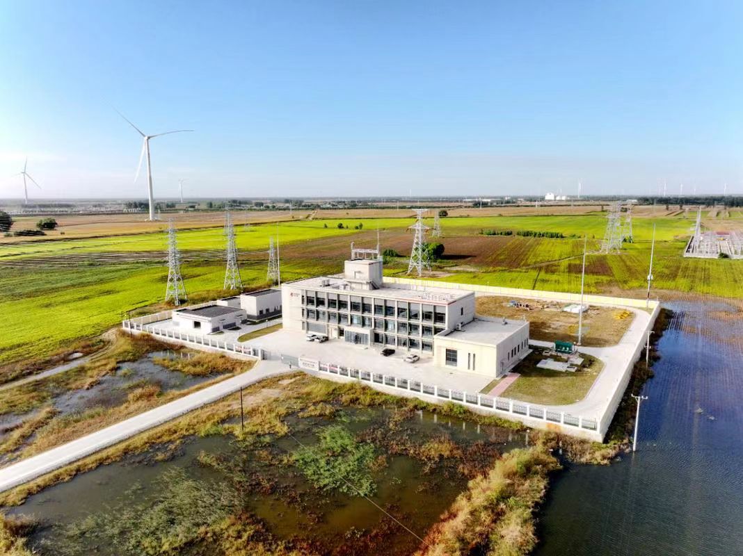
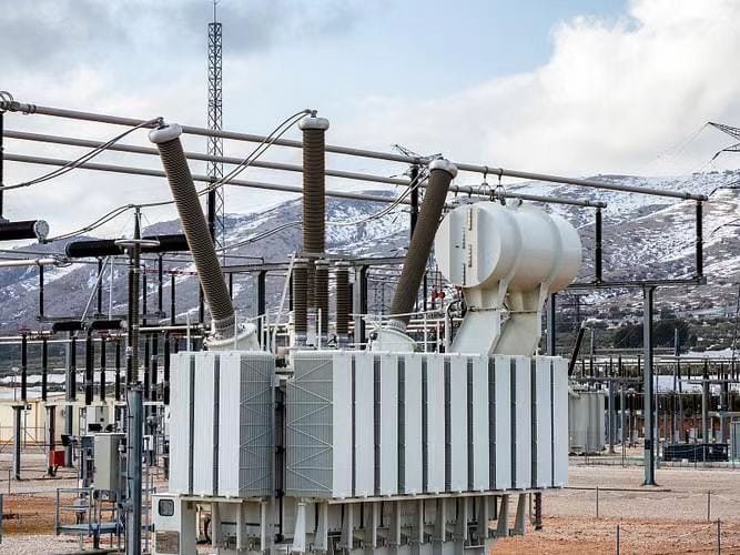
As renewable energy generation continues to scale globally, the focus has shifted from just producing clean power to also efficiently integrating that power into the grid. Wind farms, solar fields, hydro plants, and battery storage systems all generate electricity at voltages and current levels that aren’t compatible with transmission or distribution grids directly. This is where transformers play a mission-critical role. Without transformers, the power produced from renewable sources could not be delivered over long distances, integrated with existing grids, or safely used by homes and businesses. This article explains the role of transformers in renewable energy systems, how they work in different renewable configurations, and why they are essential to the global energy transition.
Transformers in renewable energy systems are used to step up the low-voltage output from solar panels, wind turbines, and hydro generators to medium or high-voltage levels suitable for grid transmission. They ensure voltage compatibility, grid synchronization, and protection of both equipment and consumers. Without transformers, renewable power cannot be efficiently exported or safely integrated into utility-scale systems.
From inverter-level step-up transformers in solar PV systems to massive collector substations in offshore wind farms, these devices are the unsung heroes of renewable grid connection.
Transformers are essential in renewable energy systems for voltage matching and grid integration.True
They step up the low-voltage output of generators to match the grid's voltage level, enabling efficient transmission and distribution.
Renewable energy systems can connect directly to the high-voltage grid without transformers.False
Most renewable sources generate power at low voltage levels and must be stepped up via transformers to match grid standards.
Why Transformers Are Needed in Renewable Energy Systems
| Reason | Explanation |
|---|---|
| Voltage Mismatch | Solar panels and wind turbines output low voltage (400–690 V) |
| Grid Compatibility | Grid typically operates at 11 kV, 33 kV, 66 kV, or higher |
| Transmission Efficiency | Higher voltage reduces current, minimizing I²R losses |
| Fault Isolation & Protection | Transformers provide insulation and support fault detection |
| Flexible System Integration | Enable integration with inverters, SCADA, and battery storage systems |
Transformers form the bridge between renewable energy generation and grid-level consumption.
Types of Transformers Used in Renewable Systems
| Transformer Type | Function | Application |
|---|---|---|
| Inverter/Pad-Mounted Transformer | Steps up inverter output voltage to 11 kV or 33 kV | Solar PV farms, small wind turbines |
| Collector Substation Transformer | Aggregates multiple inputs and steps up to HV grid level | Wind farms, large solar installations |
| Dry-Type Transformer | Air-cooled transformer for compact, indoor installations | Rooftop solar systems, commercial buildings |
| Skid-Mounted Transformer | Integrated solution with inverter, switchgear, and transformer | Utility-scale solar and hybrid systems |
| Floating Transformer | Specialized marine-grade unit for offshore wind | Offshore substations and floating platforms |
Each type is chosen based on environmental conditions, capacity, and voltage level.
Transformer Use Case Examples in Renewable Energy
| Renewable Source | Generation Voltage | Transformer Role | Grid Connection Voltage |
|---|---|---|---|
| Solar PV Plant | 400–690 V | Step-up to 11 kV or 33 kV via inverter transformer | 11/33 kV |
| Wind Farm (Onshore) | 690 V | Collector transformers step-up to 33–66 kV | 66–132 kV |
| Wind Farm (Offshore) | 690 V | Step-up to 132–220 kV for undersea cable export | 132–220 kV |
| Hydro Plant (Small) | 400 V–11 kV | Step-up to 33 kV or 66 kV for rural distribution | 33 kV |
| Battery Energy Storage System (BESS) | 400–800 V DC | Inverter + transformer combo to AC grid voltage | 11–33 kV |
Grid Integration Architecture with Transformers
| System Stage | Voltage Level | Transformer Used |
|---|---|---|
| Renewable Generator Output | 400–690 V | Inverter transformer |
| Local Feeder/Collector Circuit | 11–33 kV | Pad/skid-mounted collector transformer |
| Export Substation | 66–220 kV | Power transformer or autotransformer |
| Transmission System | 220–400 kV | Grid interconnect transformer (if required) |
This step-by-step voltage escalation ensures efficient and safe power delivery over vast distances.
Protection and Monitoring Enabled by Transformers
| Feature | Transformer Role |
|---|---|
| Voltage Regulation | Tap changers maintain voltage under load fluctuations |
| Fault Isolation | Separates generator faults from the grid |
| Harmonic Filtering | Limits distortion from inverter output |
| Ground Fault Control | Supports system earthing and neutral grounding |
| SCADA Integration | Sensors within transformers provide real-time data |
Renewable transformers are often smart-enabled, feeding real-time data to utility operators.
Challenges Unique to Renewable Transformers
| Challenge | Transformer Design Consideration |
|---|---|
| Variable Output (e.g. solar)** | Designed to handle frequent load cycling |
| Harmonics from Inverters | Low-impedance, high-damping core construction |
| Outdoor Harsh Environments | Corrosion-resistant enclosures, IP-rated housing |
| Limited Installation Space | Compact pad or skid-mounted designs |
| Voltage Fluctuations | OLTC or fixed-tap adjustments for better voltage stability |
Specialized transformers ensure maximum uptime and minimal energy loss, even under intermittent supply conditions.
How Do Audio Transformers Serve a Unique Purpose?
In professional audio systems, sound clarity, signal integrity, and noise suppression are paramount. Whether it's a recording studio, live concert, or broadcast facility, even the tiniest buzz, hum, or ground loop can ruin a performance or production. This is where audio transformers come in—not for voltage transformation like power transformers, but to serve very specific signal-level functions. Unlike conventional transformers, audio transformers are engineered for fidelity, impedance matching, galvanic isolation, and noise rejection. In this article, we explain how audio transformers serve a unique purpose in audio engineering, what makes them different, and why they remain indispensable even in today's digital world.
Audio transformers serve a unique purpose by providing galvanic isolation, impedance matching, common-mode noise rejection, and balanced-to-unbalanced signal conversion in audio systems. They allow audio signals to be transferred cleanly between devices while blocking DC, hum, and interference. This ensures high-fidelity sound and reliable signal integrity, especially in professional and broadcast environments.
Whether embedded in microphones, mixers, DI (direct input) boxes, or amplifiers, audio transformers quietly ensure that what you hear is exactly what was recorded—without distortion or interference.
Audio transformers are used to isolate and balance audio signals while preventing noise and interference.True
They block unwanted ground loops and common-mode noise while preserving signal fidelity and level matching.
Audio transformers serve the same purpose as power transformers in voltage step-up or step-down.False
Audio transformers work at signal level, not power level, and are optimized for fidelity and impedance rather than power transfer.
Key Roles of Audio Transformers
| Function | Purpose in Audio Systems |
|---|---|
| Galvanic Isolation | Prevents ground loops and DC offset between connected equipment |
| Impedance Matching | Ensures maximum signal transfer between devices with differing impedances |
| Common-Mode Noise Rejection | Eliminates hum and interference picked up over cables |
| Balanced–Unbalanced Conversion | Converts unbalanced signals (e.g., guitars) to balanced XLR format |
| DC Blocking | Removes unwanted DC components from audio paths |
These functions make audio transformers a critical part of analog audio design, signal routing, and protection.
Where Audio Transformers Are Used
| Application | Transformer Role |
|---|---|
| Microphones (Dynamic/Tube) | Isolates mic signal, balances output |
| DI Boxes (Direct Input) | Converts high-impedance instrument signals to balanced mic level |
| Mixing Consoles | Balances incoming/outgoing channels, prevents interference |
| Studio Patch Bays | Ensures clean routing between analog gear |
| Amplifiers and Headphone Outputs | Matches load, isolates stages, prevents noise |
| Broadcast Systems | Preserves long-distance signal integrity |
Audio transformers are commonly found in XLR, TRS, and RCA signal chains—especially in analog setups and high-end systems.
Audio vs Power Transformers: What Makes Them Different?
| Characteristic | Audio Transformer | Power Transformer |
|---|---|---|
| Frequency Range | 20 Hz – 20 kHz (audio spectrum) | 50 Hz / 60 Hz (AC grid frequency) |
| Core Material | High-permeability, low-loss core (e.g., mu-metal) | Silicon steel or amorphous core |
| Turns Ratio | 1:1 or optimized for impedance (not voltage) | Designed for voltage step-up/down |
| Impedance Focus | Critical (matching source/load) | Not applicable |
| Noise Consideration | Designed to reduce EMI and crosstalk | Not sensitive to high-frequency interference |
| Size and Power Handling | Small, signal-level (milliwatts) | Large, kilowatt-range |
Audio transformers prioritize signal integrity and fidelity over raw power transfer.
Typical Audio Transformer Specifications
| Parameter | Typical Range |
|---|---|
| Turns Ratio | 1:1, 1:2, 2:1, or custom |
| Impedance Rating | 600 Ω, 10k Ω, 100k Ω |
| Bandwidth | 20 Hz to 20 kHz (flat within ±0.5 dB) |
| THD (Total Harmonic Distortion) | < 0.1% at 1 kHz |
| Insertion Loss | < 1 dB |
| Shielding | Mu-metal cans for EMI protection |
| Size | Small, PCB-mount or chassis-mount |
Real-World Example: Passive DI Box with Audio Transformer
| Component | Function |
|---|---|
| High-Impedance Input (1 MΩ) | Connects electric guitar or keyboard |
| Step-Down Transformer (10:1) | Converts to low-Z balanced output (600 Ω) |
| XLR Output | Feeds mic input of mixing console |
| Transformer Isolation | Prevents 60 Hz hum from ground loops |
This setup allows a clean, hum-free signal to be sent from a noisy stage to the mixer hundreds of feet away.
Benefits of Using Audio Transformers
| Benefit | Impact on Audio Quality |
|---|---|
| Noise-Free Operation | Blocks EMI and hum from cables and power supplies |
| Improved Headroom | Prevents clipping and distortion in audio stages |
| Cleaner Signal Routing | Balances and isolates audio paths without introducing artifacts |
| Compatibility Across Gear | Bridges legacy and modern equipment with differing impedances |
| Fail-Safe Performance | No active circuitry—robust and long-lasting |
For professional studios and live audio, audio transformers are essential for ensuring broadcast-grade performance.
When Not to Use Audio Transformers
| Condition | Alternative |
|---|---|
| Extremely low distortion required | Transformerless balanced outputs (active circuits) |
| Digital audio systems | Use optical or AES/EBU interfaces |
| High-frequency analog (>20 kHz) | Use op-amp buffering instead |
Still, for analog audio in electrically noisy environments, transformers outperform digital isolation methods in many scenarios.
What Are Furnace Transformers and Where Are They Used?
In the harsh, energy-hungry environments of steel mills, foundries, and glass factories, specialized equipment is required to handle the intense electrical demands of melting metals. This is the domain of the furnace transformer—a robust and custom-engineered power transformer that can deliver extremely high currents at low voltages, tailored for electric arc furnaces (EAF), ladle furnaces (LF), and induction furnaces. These transformers are the beating heart of industrial heating systems, converting electrical energy into thermal energy with precision, durability, and safety. In this article, we’ll explain what furnace transformers are, how they work, and where they’re used in industry.
Furnace transformers are heavy-duty power transformers designed to supply high-current, low-voltage power to electric furnaces used in metal melting, alloy treatment, and industrial heating processes. They are specifically engineered to handle thermal stress, short-circuit forces, and frequent on-off switching associated with arc or induction furnaces in steel plants, foundries, and non-ferrous metal industries.
These transformers are not standard grid devices—they are industrial workhorses, purpose-built for extreme electrical and thermal conditions.
Furnace transformers are used to power electric furnaces by converting grid voltage into high-current, low-voltage supply.True
They are essential for processes like arc melting, induction heating, and metal refining, enabling precise control of thermal energy.
Furnace transformers are just standard distribution transformers used in offices and residential areas.False
Unlike standard transformers, furnace transformers are engineered for high thermal, electrical, and mechanical stresses in industrial environments.
Key Features of Furnace Transformers
| Feature | Purpose |
|---|---|
| High Current Output | Delivers thousands of amperes to sustain metal melting arcs |
| Low Secondary Voltage | Maintains 100 V to 1,000 V to ensure furnace arc control |
| High Thermal Tolerance | Withstands constant heat and overloads from furnace cycles |
| Heavy-Duty Tap Changer | Regulates secondary voltage during operation |
| Mechanical Reinforcement | Resists strong electrodynamic forces caused by arc instability |
A typical furnace transformer might deliver 10 kA to 80 kA at voltages as low as 100 V, requiring extremely robust windings and cooling.
Common Types of Furnace Transformers
| Type | Application | Voltage Range | Current Range |
|---|---|---|---|
| Electric Arc Furnace (EAF) | Steel melting, recycling scrap metal | 33 kV → 300–900 V | 10,000–80,000 A |
| Induction Furnace | Non-ferrous metal melting, foundries | 11 kV → 500–1,000 V | 1,000–10,000 A |
| Ladle Furnace (LF) | Alloy refining, reheating molten steel | 33 kV → 600–1,000 V | 4,000–40,000 A |
| Submerged Arc Furnace (SAF) | Ferroalloy production, silicon, calcium carbide | 66 kV → 200–800 V | 10,000–100,000 A |
Each furnace transformer is custom-engineered based on furnace load characteristics and duty cycles.
Where Furnace Transformers Are Used
| Industry | Use of Furnace Transformers |
|---|---|
| Steel Industry | EAFs and LFs for melting scrap, producing steel alloys |
| Foundries | Induction furnaces for aluminum, brass, copper casting |
| Ferroalloy Plants | SAFs for manganese, silicon, and chromium production |
| Glass Manufacturing | Electrical melting and annealing furnaces |
| Cement & Lime Kilns | Resistive heating and arc stabilization |
| Refineries (Petrochemical) | Electrically heated reactors and thermal cracking systems |
Furnace transformers are vital to industries that depend on intense, controlled heating processes powered by electricity.
Technical Design Considerations
| Design Factor | Why It Matters |
|---|---|
| Cooling System (OFAF/OFWF) | Required to remove intense heat due to high current density |
| Tap Changer (OLTC) | Adjusts voltage in real-time to stabilize arc behavior |
| Short-Circuit Strength | Must handle frequent high-current transients during arcing |
| Copper or Aluminum Windings | Depends on cost, performance, and load duty |
| Bushing & Terminal Design | Must accommodate high mechanical stress and massive cable size |
| Secondary Connection Configuration | Often delta or zig-zag to handle unbalanced arc loads |
A poorly designed transformer risks overheating, insulation failure, and furnace shutdown, which can cause major production losses.
Furnace Transformer Performance Metrics
| Parameter | Typical Value / Range |
|---|---|
| Primary Voltage | 11 kV, 22 kV, 33 kV, or 66 kV |
| Secondary Voltage | 100 V to 1,200 V (stepped down with taps) |
| Rated Power (MVA) | 5 MVA to 100+ MVA |
| Duty Cycle | Intermittent (batch melting) or continuous (induction) |
| Cooling Type | OFAF (oil forced, air forced), OFWF (oil-water) |
Transformer design must also account for arc flicker, waveform distortion (harmonics), and mechanical vibrations.
Comparison: Furnace vs Standard Power Transformer
| Feature | Furnace Transformer | Standard Power Transformer |
|---|---|---|
| Voltage Range | Medium to ultra-low secondary | High to medium voltage |
| Current | Extremely high (10 kA to 80 kA) | Low to moderate (up to a few kA) |
| Thermal Design | Oversized radiators, multiple fans | Standard ONAN/ONAF systems |
| Tap Changer Duty | Frequent adjustments during operation | Infrequent or fixed |
| Mechanical Stiffness | Extra bracing for dynamic arc forces | Not as reinforced |
Conclusion
Transformers are far more than voltage regulators in power grids. Their special purposes—from isolating circuits and ensuring safety to managing power in medical, audio, and industrial environments—highlight their incredible versatility. Understanding these specialized roles helps illustrate why transformers are foundational to both modern industry and advanced technology systems.
FAQ
Q1: What is the special purpose of a transformer?
A1: While transformers are mainly used for voltage conversion, their special purposes include:
Electrical isolation between circuits for safety
Voltage regulation under varying load conditions
Measurement and protection in power systems
Signal transformation in communication systems
Power conditioning for sensitive equipment
Q2: What are isolation transformers and their special purpose?
A2: Isolation transformers are used to electrically separate two circuits while allowing energy transfer. They provide safety in hospitals, labs, and electronic equipment by preventing ground loops and reducing the risk of electric shock.
Q3: What are instrument transformers and why are they special?
A3: Instrument transformers include current transformers (CTs) and voltage transformers (VTs), which are used for:
Measuring electrical parameters in high-voltage systems
Isolating metering and protection devices from high voltage
They ensure accurate monitoring and safe operation of power networks.
Q4: What other special-purpose transformers exist?
A4: Examples include:
Furnace transformers for steel and arc furnaces
Rectifier transformers for converting AC to DC
Traction transformers for railway and electric transport
Medical transformers for patient-isolated equipment
Audio transformers for impedance matching in sound systems
Q5: Why are special-purpose transformers critical in industry?
A5: These transformers meet specific voltage, frequency, safety, or operational needs that general-purpose transformers cannot. They ensure precision, protection, and efficiency in critical infrastructure, from manufacturing lines to research labs.
References
"Special Purpose Transformers Explained" – https://www.transformertech.com/special-purpose-transformers – Transformer Tech
"Types and Applications of Special Transformers" – https://www.powermag.com/special-transformer-uses – Power Magazine
"What Makes a Transformer ‘Special Purpose’?" – https://www.electrical4u.com/special-purpose-transformers – Electrical4U
"Instrument and Isolation Transformers in Power Systems" – https://www.researchgate.net/instrument-transformers – ResearchGate
"Industrial Applications of Special Transformers" – https://www.sciencedirect.com/special-transformers-applications – ScienceDirect
"Smart Grid and Non-Standard Transformer Roles" – https://www.smartgridnews.com/special-transformer-applications – Smart Grid News
"Energy Central: Understanding Unique Transformer Needs" – https://www.energycentral.com/c/ee/special-transformers-explained – Energy Central
"PowerGrid: Specialized Transformer Technologies" – https://www.powergrid.com/special-transformer-guide – PowerGrid