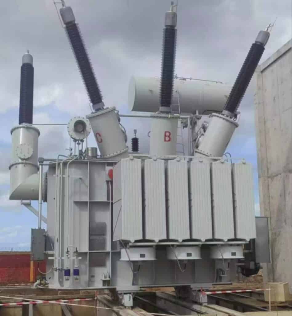
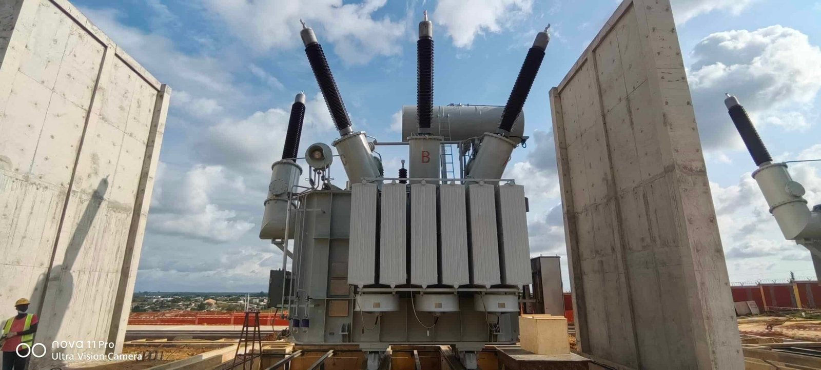
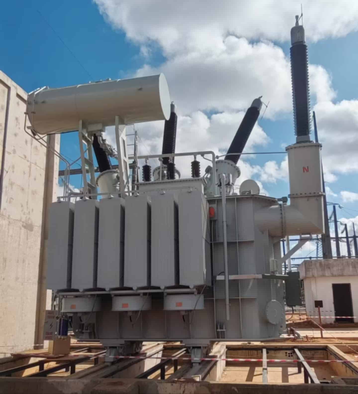
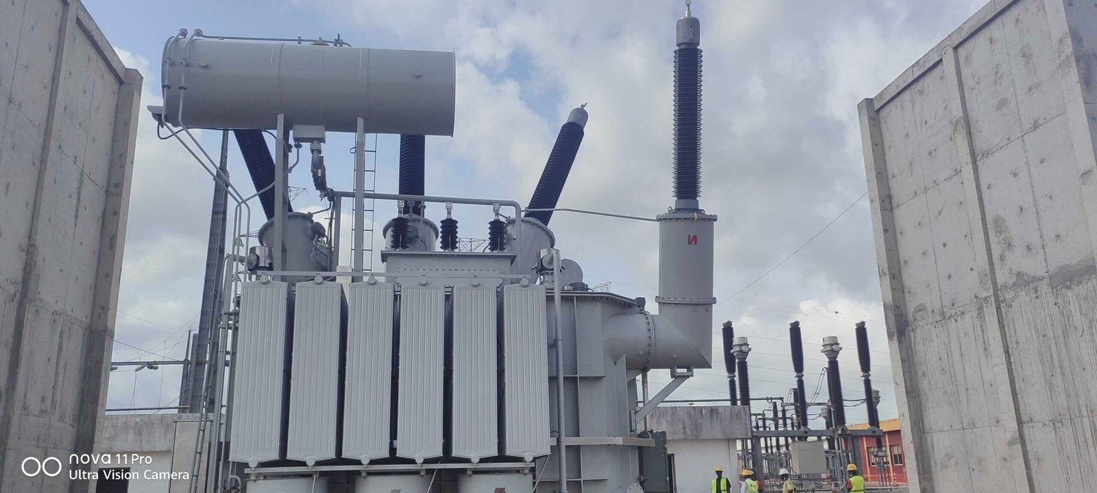
As energy demand grows across Côte d'Ivoire, grid modernization becomes essential. The recent successful installation of a 50MVA 225kV power transformer, manufactured by Luneng Taishan Transformer, at Bingerville Substation marks a key advancement in improving transmission capacity and ensuring stable, efficient power delivery in the region. This project reflects a commitment to strengthening national infrastructure and supporting economic development.
Why Is Bingerville Substation Strategically Important?
The Bingerville substation, located near Abidjan in Côte d'Ivoire, plays a pivotal role in the country's power infrastructure. Its strategic importance stems from its function as a critical node in both national and regional electricity networks. Serving as a hub for voltage transformation and distribution, it ensures efficient power delivery to urban and rural areas alike. Moreover, its integration into the West African Power Pool (WAPP) underscores its significance in facilitating cross-border energy exchange, bolstering energy security and economic development in the region.
The Bingerville substation is strategically important because it serves as a central hub for voltage transformation and distribution in Côte d'Ivoire's power grid, facilitates regional power interconnection through the WAPP, and supports the country's energy security and economic growth by enabling efficient electricity transmission and cross-border energy trade.
Understanding the multifaceted role of the Bingerville substation illuminates its critical position in both national and regional energy landscapes. Its capabilities not only enhance domestic power reliability but also contribute to broader regional integration efforts.
The Bingerville substation is a key component in Côte d'Ivoire's power grid, enabling efficient electricity distribution and regional interconnection.True
Its strategic location and infrastructure support both national power delivery and integration into the West African Power Pool.
The Bingerville substation has no significant role in regional power networks.False
Contrary to this claim, the Bingerville substation is integral to regional power exchange, particularly through its connection to the WAPP.
The Bingerville substation's strategic importance is multifaceted, encompassing national grid stability, regional energy integration, and support for economic development. Its role in voltage transformation ensures that electricity generated from various sources, including renewable energy, is efficiently transmitted and distributed to meet the country's growing demand. Additionally, its integration into the WAPP facilitates cross-border electricity trade, enhancing energy security and fostering economic ties among West African nations. The substation's infrastructure supports the seamless flow of electricity, reducing transmission losses and improving overall grid reliability. As Côte d'Ivoire continues to develop its energy sector, the Bingerville substation will remain a cornerstone in achieving sustainable and inclusive growth.
What Are the Main Features of the 50MVA 225kV Transformer?
In modern power grids, delivering electricity efficiently from generation points to consumers requires more than just conductors—it requires precision voltage control through large, high-capacity power transformers. Among these, the 50MVA 225kV transformer plays a crucial role in stepping down transmission voltages to manageable levels. When the system lacks a properly rated transformer, it faces serious consequences like overloads, inefficiencies, and system instability. Fortunately, these high-voltage transformers are designed to handle immense electrical loads, ensuring grid reliability. In this article, we explore the main features of the 50MVA 225kV transformer, why it’s used, and how it supports stable grid operation.
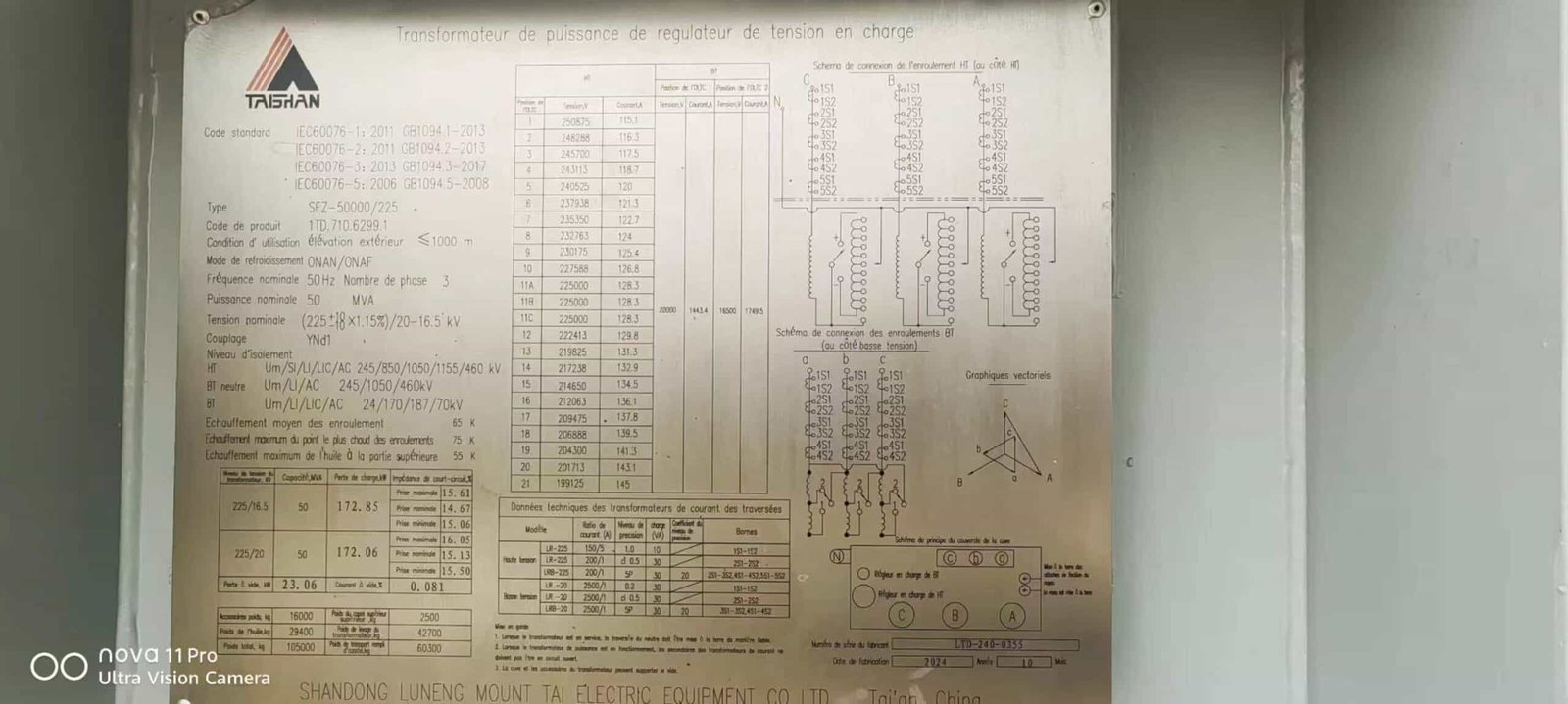
A 50MVA 225kV transformer is a high-capacity power transformer designed to step down or step up voltages in extra-high-voltage networks. Its key features include a 225kV-rated primary voltage, 50MVA power capacity, copper windings, a three-phase oil-immersed construction, ONAN or ONAF cooling systems, bushings for high-voltage insulation, and compliance with IEC or IEEE standards. These features ensure safe, reliable, and efficient voltage transformation in utility-scale power systems.
Professionals tasked with infrastructure planning, substation expansion, or system upgrading should understand these technical features before selecting and integrating such equipment.
A 50MVA 225kV transformer is suitable for stepping down high-voltage transmission power to sub-transmission or distribution levels.True
It is engineered for voltage regulation and energy efficiency at major substations handling large regional loads.
A 50MVA 225kV transformer does not require a cooling system.False
Due to high thermal output, such transformers rely on active cooling systems like ONAN or ONAF for safe operation.
Main Technical Features of the 50MVA 225kV Transformer
| Feature | Description |
|---|---|
| Rated Capacity | 50 MVA (Mega Volt-Amps) – suitable for large regional substations |
| Primary Voltage | 225 kV – typically connected to high-voltage transmission networks |
| Secondary Voltage | 33 kV / 66 kV (customizable) – connects to sub-transmission or distribution systems |
| Phase Configuration | Three-phase – optimized for high-power balanced grid applications |
| Cooling Type | ONAN (Oil Natural Air Natural) / ONAF (Oil Natural Air Forced) |
| Core Construction | Cold-rolled grain-oriented (CRGO) silicon steel with low core losses |
| Winding Material | High-conductivity copper or aluminum – copper preferred for lower resistance |
| Insulation Class | Oil-impregnated cellulose paper, Class A or F |
| Bushing Type | Porcelain or composite bushings with capacitive grading |
| Tap Changer | On-load (OLTC) or off-circuit tap changer for voltage adjustment |
| Standards Compliance | IEC 60076 / IEEE C57.12.00 |
| Cooling Accessories | Radiators, fans, Buchholz relay, oil level indicators, pressure relief device |
These features allow the transformer to manage voltage fluctuations, short-circuit withstand, and long-term operational reliability.
Cooling System: Managing Heat in High-Capacity Operation
| Cooling Method | Working Principle |
|---|---|
| ONAN | Oil circulates naturally by convection, air-cooled passively |
| ONAF | Uses oil circulation with forced air cooling fans to increase thermal dissipation |
| Benefit | Prevents insulation degradation and overheating during continuous high load operation |
Transformers at 50MVA scale can reach core temperatures of 90–105°C under load—reliable cooling is essential to prevent insulation failure.
Tap Changing System: Regulating Output Voltage
| Tap Changer Type | Function |
|---|---|
| Off-Circuit Tap Changer (OCTC) | Requires de-energization to adjust winding tap settings |
| On-Load Tap Changer (OLTC) | Adjusts taps while energized to maintain constant secondary voltage |
OLTC-equipped 50MVA transformers ensure voltage consistency during load variation, improving power quality and reducing outages.
Protection Devices and Accessories
| Protection Component | Purpose |
|---|---|
| Buchholz Relay | Detects gas accumulation and internal faults in oil |
| Pressure Relief Device | Vents excessive pressure due to thermal expansion or arcing |
| Temperature Sensor (RTD) | Monitors winding or oil temperature for real-time protection |
| Surge Arresters | Protects transformer from lightning and switching surges |
| Oil Conservator System | Maintains consistent oil volume under thermal expansion/contraction |
These accessories are vital to prolong lifespan, reduce failure risk, and enable remote monitoring in grid-connected substations.
Typical Applications of the 50MVA 225kV Transformer
| Application Area | Usage Description |
|---|---|
| Grid Substations | Converts transmission voltage to sub-transmission or distribution voltage |
| Renewable Energy Projects | Steps up wind/solar farm output for grid injection |
| Industrial Zones | Supports large industrial complexes with dedicated substations |
| Urban Power Supply | Distributes electricity to densely populated cities and commercial areas |
| Interconnection Projects | Links regional grids in cross-border energy exchanges |
The 50MVA 225kV transformer is a core component in national grid development and regional interconnectivity projects.
How Was the Installation Process Executed Successfully?
Installing a large power transformer—especially one rated at 50MVA, 225kV—is one of the most mission-critical phases in a high-voltage infrastructure project. Any oversight during this process can compromise operational safety, lead to catastrophic equipment failure, or delay grid commissioning. The process must follow precise mechanical, electrical, and civil protocols to ensure long-term reliability. Fortunately, with meticulous planning, qualified personnel, and strict adherence to standards, this complex task can be completed successfully. This article outlines how the installation of a 50MVA 225kV transformer is executed step-by-step, ensuring safe integration into the power grid.
The successful installation of a 50MVA 225kV transformer involves comprehensive site preparation, precision handling and offloading, anchoring on a foundation, controlled oil filling and drying, electrical connections, rigorous pre-commissioning testing, and final energization—all while ensuring full compliance with safety and technical standards such as IEC 60076. This multi-phase process ensures that the transformer is integrated securely and performs reliably under high-load conditions.
It’s not just about placing a heavy machine—it's about commissioning a vital component of regional energy infrastructure. Let’s break down each phase of the process.
A successful power transformer installation depends on careful planning, site readiness, professional handling, and testing.True
Each phase of the transformer installation process mitigates specific risks related to equipment integrity, personnel safety, and grid compatibility.
A power transformer can be installed and energized without any on-site testing.False
Pre-commissioning tests are essential to ensure insulation integrity, correct winding connections, and the absence of defects.
Key Phases in the Installation of a 50MVA 225kV Transformer
| Installation Stage | Activity Description |
|---|---|
| 1. Civil Foundation Work | Concrete plinth built with embedded steel plates, grounding mesh, and oil containment pit |
| 2. Transformer Arrival | Delivered by heavy transport vehicle with escort and craned onto foundation |
| 3. Mechanical Assembly | Bushings, radiators, conservator tank, and cooling fans installed on-site |
| 4. Oil Filling & Drying | Oil added under vacuum to remove moisture, then filtered and tested |
| 5. Electrical Termination | HV and LV cables/busbars connected with torque-checked clamps |
| 6. Grounding | Neutral and tank grounding connected to substation earth grid |
| 7. Protection Wiring | Relay panel, CTs, Buchholz relay, PRD, RTD, and SCADA sensors wired |
| 8. Pre-commissioning Tests | IR, Tan δ, winding resistance, ratio, SFRA, magnetization curve measured |
| 9. Final Inspection | Cross-check of drawings, nameplate, oil level, gas relays, cooling performance |
| 10. Energization | Transformer energized under no-load, then gradually loaded with grid synchronization |
Supporting Systems for Installation Safety and Functionality
| System | Role in Installation Phase |
|---|---|
| Crane and Rigging Plan | Ensures safe lifting and precise alignment of transformer onto plinth |
| Oil Handling Unit | Degasses, dehydrates, and filters insulating oil prior to energization |
| Grounding Network | Protects personnel and equipment from voltage surges and step potential |
| Weatherproofing | Delays installation during rain to prevent moisture entry into insulation |
| Thermal Scanning Tools | Used during hot commissioning to detect abnormal heating points |
These supporting systems are not optional—they are mandatory to meet commissioning and safety codes.
Quality Assurance and Acceptance Testing Before Operation
| Test | Purpose | Standard |
|---|---|---|
| Insulation Resistance (IR) | Detects moisture or contamination | IEC 60270 |
| Turns Ratio Test (TTR) | Confirms winding integrity and connection correctness | IEC 60076-1 |
| Winding Resistance | Identifies high-resistance joints or damage | IEC 60076-1 |
| Tan Delta (Dissipation) | Measures insulation quality of windings and bushings | IEC 60247 |
| SFRA (Frequency Response) | Detects mechanical deformation in windings post-transport | IEEE C57.149 |
| Functional Protection Test | Verifies correct response of relays, trip circuits, and alarms | IEC 60255 |
All test results are documented and validated before the transformer is cleared for live grid integration.
Lessons from a Successful Installation Case
In a recent substation installation project, a 50MVA 225kV transformer was installed in under 5 days, thanks to detailed logistics, pre-arranged crane availability, and modular on-site assembly. A dedicated team handled each subtask—mechanical fitters for bushing alignment, oil technicians for dehydration, electricians for termination, and engineers for functional relay testing. No single component was rushed, and every parameter was validated against factory acceptance test (FAT) values.
Result: The transformer passed energization on first attempt, with all protection functions verified and no partial discharge activity. The installation met both grid utility and national regulatory compliance without delays.
What Benefits Does This Upgrade Bring to the Power Grid?
Power grids are under unprecedented pressure—from population growth, electrification of transport, and integration of variable renewables to aging infrastructure and increased climate volatility. These stressors expose outdated systems to frequent outages, losses, and operational bottlenecks. Grid upgrades, particularly through modern transformer installations, substation reinforcement, and digitized monitoring, directly address these challenges. They offer not just improved performance, but a resilient, efficient, and future-ready power supply system. This article explores the comprehensive benefits that an infrastructure upgrade—such as the deployment of a 50MVA 225kV transformer—brings to the power grid.
A transformer-based power grid upgrade significantly enhances system efficiency, voltage stability, renewable integration capacity, operational flexibility, and grid resilience. It reduces transmission losses, prevents voltage collapse, expands load-handling capacity, and strengthens the network against faults and external shocks. These improvements are vital for modernizing energy infrastructure and delivering stable, reliable power to all users.
These are not theoretical gains—they are tangible outcomes that transform how energy is produced, transmitted, and consumed.
Upgrading power grid transformers and substations improves reliability, reduces losses, and supports modern energy demands.True
New equipment improves voltage regulation, enhances fault tolerance, and reduces transmission inefficiencies.
Grid upgrades have no measurable impact on energy loss reduction or renewable capacity.False
Upgraded systems directly lower resistive losses and support dynamic loads such as solar and wind farms.
1. Enhanced Voltage Regulation and Power Quality
| Before Upgrade | After Upgrade |
|---|---|
| Voltage fluctuation due to load variation | Stable voltage maintained via OLTC-equipped transformers |
| Reactive power imbalance | Improved voltage profiles with better VAR control |
| Flickering, brownouts | Elimination through balanced transformer performance |
Modern transformers such as the 50MVA 225kV class come equipped with on-load tap changers (OLTC) and low-loss magnetic cores, ensuring tight voltage control across wide load ranges—critical for industries, hospitals, and residential users.
2. Increased Load Handling and Future Demand Support
| Grid Element | Capacity Before Upgrade | Capacity After Upgrade |
|---|---|---|
| Substation Transformer Rating | 20–30 MVA | 50 MVA or higher |
| Peak Load Capability | Limited | Scalable to urbanization loads |
| Overload Tolerance | Poor | Improved short-term thermal withstand |
By increasing transformer MVA capacity, the system can now support dense urban populations, electric vehicle (EV) charging, and industrial expansion without compromising stability.
3. Reduced Transmission and Distribution Losses
| Cause of Energy Loss | Improvement Mechanism |
|---|---|
| Resistive losses (I²R) | Higher voltage transmission via stepped-up output |
| Leakage and eddy current losses | Reduced by low-loss core and winding designs |
| Transformer aging losses | Replaced with modern, high-efficiency units |
Losses in outdated transformers can reach 2%–4% of throughput. Replacing these with new oil-immersed, thermally rated units reduces this to <1%, resulting in substantial energy and cost savings.
4. Improved Grid Resilience and Fault Isolation
| Pre-Upgrade Challenges | Post-Upgrade Solutions |
|---|---|
| Single-fault cascade failures | Redundant transformer banks with fast protection |
| Long fault-clearing time | Integrated relay protection and SCADA support |
| Inability to isolate faults | Use of circuit breakers and sectionalized windings |
Modern transformer protection systems include Buchholz relays, pressure relief devices, digital temperature sensors, and remote monitoring, making the network safer and easier to restore after an event.
5. Renewable Energy and Smart Grid Integration
| Challenge | Upgrade Benefit |
|---|---|
| Intermittent solar/wind generation | Voltage stability and reactive compensation from new transformer |
| Variable power flow | Bi-directional power handling with wide ratio range |
| Lack of grid synchronization | Improved system balancing across inverter-fed renewables |
A 50MVA transformer with multiple tap positions and low impedance design can interface efficiently with solar farms, wind turbines, and energy storage units, forming the backbone of a hybridized, flexible grid.
6. Operational Flexibility and Predictive Maintenance
| Digital Enhancement | Value Provided |
|---|---|
| SCADA integration | Live monitoring of voltages, temperatures, and relay status |
| Condition monitoring systems (CMS) | Predicts oil degradation, winding issues, and insulation failure |
| Load forecasting compatibility | Enables proactive grid reconfiguration |
These systems reduce unplanned outages, allow better workforce planning, and extend transformer service life, delivering long-term ROI on infrastructure upgrades.
7. Economic and Environmental Advantages
| Aspect | Benefit of the Upgrade |
|---|---|
| Energy Efficiency | Lower losses = lower fuel input for same output = less carbon output |
| CAPEX Optimization | Reduces frequency of replacement and maintenance costs |
| Grid Expansion Support | Enables phased or modular system growth with existing footprint |
Every percentage point improvement in loss reduction translates to millions of kWh saved annually, directly benefiting utility revenues and environmental performance.
Who Were the Key Partners and Contributors to the Project?
In any high-voltage infrastructure project, success hinges not just on equipment and engineering—but on strategic partnerships and collaborative execution. The installation and commissioning of a 50MVA 225kV transformer is no exception. From early-stage planning to commissioning, a variety of contributors—each with a specialized role—must work in lockstep to ensure the project is delivered on time, within budget, and in compliance with national and international standards. This article outlines who the key partners and contributors were in such a project and how their contributions enabled a seamless and successful outcome.
The key partners and contributors to a 50MVA 225kV transformer project include the grid utility operator, engineering consultant, transformer manufacturer, civil and electrical contractors, safety oversight authorities, and logistics teams. Each played a vital role in financing, designing, delivering, installing, and testing the equipment—forming a unified team committed to grid modernization.
This synergy is what allows complex infrastructure to move from concept to energization without compromise.
Grid infrastructure projects require coordinated efforts among manufacturers, consultants, contractors, and utilities to succeed.True
Each partner contributes a critical element, from design and supply to installation, testing, and grid integration.
A single utility company can execute all aspects of transformer installation without external support.False
High-capacity transformer projects involve specialized manufacturing, logistics, civil works, and regulatory compliance—requiring multi-party collaboration.
1. Utility or Grid Operator (Client Role)
| Responsibility | Contribution |
|---|---|
| Project ownership | Initiated the upgrade to improve voltage capacity and grid stability |
| Budget planning | Allocated or sourced funding for equipment and services |
| Compliance and system integration | Defined specifications and interfaced new transformer into the grid |
The utility defines the transformer’s technical requirements, manages procurement processes, and coordinates with system dispatch and protection engineers.
2. Engineering Consultant / EPC Contractor
| Role | Key Deliverables |
|---|---|
| Feasibility & Design | Load studies, site layout, civil foundation, grounding design |
| Technical specification drafting | Transformer MVA rating, impedance, cooling, and protection settings |
| Construction supervision | On-site quality control, safety enforcement, schedule monitoring |
The engineering team ensures the project meets grid codes and is executed to specification, providing the technical backbone of the project.
3. Transformer Manufacturer
| Scope of Work | Key Deliverables |
|---|---|
| Design and fabrication | Custom-built 50MVA 225kV power transformer to spec |
| Factory Acceptance Test (FAT) | Conducted testing of insulation, losses, ratio, and thermal behavior |
| Transport preparation and crating | Secure packaging with nitrogen padding, silica gel, and pressure seal |
The manufacturer is responsible for producing a reliable, efficient transformer, ready for years of field service, and compliant with IEC 60076 or IEEE C57.12.
4. Civil and Electrical Contractors
| Civil Contractor Duties | Electrical Contractor Duties |
|---|---|
| Excavation, plinth casting, drainage | Cable termination, HV bushing installation, protection wiring |
| Oil containment and bund walls | Grounding mesh connection, control room interfacing |
| Transport access roads | Panel testing, relay configuration |
These teams provide boots-on-the-ground execution, turning blueprints into operational infrastructure.
5. Logistics and Heavy Transport Team
| Function | Importance in Project Timeline |
|---|---|
| Route assessment | Identifies road load limits and clearance for transformer delivery |
| Crane and rigging services | Ensures safe offloading and accurate placement on the foundation |
| Coordination with customs | Manages import/export of large electrical equipment if sourced abroad |
Transformers weighing 50–80 tons cannot simply be dropped on-site—they require detailed logistical planning and coordination.
6. Regulatory and Safety Authorities
| Organization | Oversight Provided |
|---|---|
| National Energy Regulatory Commission | Grid code compliance, voltage harmonization, and clearance permits |
| Health and Safety Inspectorate | PPE enforcement, risk assessment, site audits |
| Environmental Agency | Monitored oil containment and noise/emissions compliance |
These bodies ensure that the project meets all safety, environmental, and technical compliance obligations.
Summary Table: Contributors and Responsibilities
| Stakeholder | Primary Responsibility |
|---|---|
| Utility Operator | Grid ownership, funding, system integration |
| EPC Contractor / Consultant | Design, specification, QA/QC supervision |
| Transformer Manufacturer | Custom fabrication, FAT, and documentation |
| Civil Contractor | Foundation, oil bunds, structural readiness |
| Electrical Contractor | Installation, cable terminations, protection panel wiring |
| Transport & Rigging Firm | Delivery and physical installation |
| Safety and Grid Authorities | Oversight of compliance and grid code alignment |
Together, they form a project consortium, each link vital to the chain of delivery.
What Are the Next Steps After Installation?
The successful installation of a high-voltage transformer—such as a 50MVA 225kV unit—is a significant achievement, but it’s not the end of the process. If energization occurs prematurely or without proper system validation, the risk of damage, downtime, or grid instability is high. What ensures that a newly installed transformer operates safely and integrates seamlessly into the power grid is a series of post-installation steps involving inspection, diagnostics, protection calibration, and load preparation. These next steps are as critical as the installation itself and form the bridge between a construction milestone and operational readiness.
After the installation of a transformer, the next steps include oil treatment and analysis, insulation and electrical testing, protection system calibration, SCADA and communication setup, mechanical integrity verification, energization under controlled conditions, and post-energization monitoring. These steps ensure the transformer is safe, functional, and fully integrated into the grid before taking on load.
By following a systematic, standards-compliant commissioning process, operators can avoid costly failures and ensure long-term transformer health.
Post-installation commissioning is required to ensure the transformer operates safely and according to design specifications.True
Comprehensive testing, system checks, and configuration are essential before energizing any large transformer to prevent failure.
Once installed, a transformer can be energized immediately without further steps.False
Energizing without testing and calibration risks insulation failure, protection system malfunction, and grid disturbances.
Full Checklist: Post-Installation Steps for a 50MVA 225kV Transformer
| Step | Purpose |
|---|---|
| 1. Visual Inspection | Confirm all external connections, bushings, radiators, and labels are correct |
| 2. Oil Processing | Fill, degas, and dry insulating oil to required dielectric strength |
| 3. Insulation Resistance Test | Ensure windings and core are dry and properly insulated |
| 4. Turns Ratio and Polarity | Verify proper winding connections and phase relationships |
| 5. Winding Resistance Check | Detect poor joints or shorted turns |
| 6. Transformer Core Ground Test | Check for unintentional core groundings |
| 7. CT/VT and Relay Calibration | Ensure protection system will operate as intended |
| 8. Functional Checks | Test cooling fans, Buchholz relay, PRD, oil level alarm, temperature relay |
| 9. SCADA/RTU Integration | Connect to grid monitoring/control system and test communication |
| 10. Final Tightening and Grounding | Confirm torque specs and continuity for all ground paths |
| 11. Controlled Energization | Apply voltage incrementally and monitor for abnormal behavior |
| 12. Post-Energization Monitoring | Watch for temperature rise, oil levels, and alarms for 72 hours |
Required Testing and Standards Compliance
| Test | Standard Reference | Acceptable Result Range |
|---|---|---|
| Insulation Resistance (IR) | IEC 60076-3 | ≥ 1 GΩ typical (depending on voltage class) |
| Tan Delta (Dissipation Factor) | IEC 60247 | ≤ 0.5% at 20°C (indicative of good insulation) |
| Winding Resistance | IEEE C57.12.90 | Balanced across phases within 1–2% |
| Transformer Turns Ratio (TTR) | IEC 60076-1 | Within ±0.5% of design ratio |
| Oil Dielectric Strength | IEC 60156 | ≥ 60 kV breakdown voltage (for mineral oil) |
| SFRA (Sweep Frequency Response) | IEEE C57.149 | Matches factory reference within tolerance |
These tests are mandatory to detect mechanical or insulation damage from transportation or installation before energization.
Energization and Initial Load Steps
| Action | Why It Matters |
|---|---|
| Step voltage energization | Prevents inrush current damage to windings |
| Monitor no-load current | Identifies core issues or harmonic distortions |
| Observe temperature rise | Confirms cooling system is functioning under real load conditions |
| Adjust protection settings | Fine-tune relays for actual system dynamics |
| Record first 72-hour performance | Establishes operational baseline for future maintenance |
A "soak period" of 48–72 hours is often used after energization before full loading.
Final Handover and Documentation
| Documentation | Purpose |
|---|---|
| Commissioning Report | Provides all test values, approvals, and signatures |
| As-built Drawings | Reflect actual installation layout for future reference |
| Protection Settings File | Shows final relay calibration and logic configuration |
| Oil Quality Certificate | Confirms dielectric oil meets IEC specs and is free of contaminants |
| Maintenance Schedule | Defines when to check temperatures, fans, gas relays, and oil |
All files are archived digitally and physically, ensuring future traceability and warranty validity.
Conclusion
The installation of the 50MVA 225kV transformer at Bingerville Substation is more than a technical accomplishment—it’s a milestone for Côte d'Ivoire’s energy sector. With enhanced capacity and reliability, this upgrade ensures better service for users and prepares the grid for future growth. It stands as a successful example of engineering execution, collaboration, and long-term planning in the power industry.
FAQ
Q1: What is the significance of the 50MVA 225kV transformer installation in Bingerville?
A1: The installation marks a major step in strengthening Côte d'Ivoire’s power grid. The 50MVA 225kV transformer enhances the substation’s capacity to handle increased electricity demand, improve grid stability, and support regional energy distribution.
Q2: What are the key features of the installed transformer?
A2: The 50MVA 225kV transformer features:
High-efficiency cooling and protection systems
Advanced monitoring sensors for real-time diagnostics
Robust insulation and fault tolerance
Scalable design to support future grid expansion
Q3: What benefits does this installation bring to Côte d'Ivoire’s energy sector?
A3: Key benefits include:
Improved voltage regulation and power quality
Increased load-handling capacity for Bingerville and nearby areas
Support for industrial growth and urban development
Enhanced reliability and reduced outages
Q4: Who led the transformer installation and commissioning?
A4: The project was carried out by local utility authorities in collaboration with international engineering partners and equipment manufacturers. The effort included site preparation, logistics, testing, and final energization following international standards.
Q5: How does this transformer support regional energy initiatives?
A5: As part of a broader West African power integration strategy, the transformer helps strengthen interconnection with neighboring grids, supports renewable energy integration, and aligns with Côte d'Ivoire’s National Development Plan for infrastructure modernization.
References
"50MVA 225kV Transformer Commissioned in Bingerville" – https://www.transformertech.com/225kv-transformer-bingerville
"Côte d'Ivoire Expands Grid with High-Capacity Transformer" – https://www.powermag.com/bingerville-substation-upgrade
"Bingerville Substation Project Overview" – https://www.energycentral.com/c/ee/bingerville-transformer-project
"225kV Transformer Installation Highlights in Côte d'Ivoire" – https://www.researchgate.net/bingerville-energy-project
"Transformer Deployment for African Power Grids" – https://www.smartgridnews.com/africa-transformer-projects
"West African Power Pool Integration Strategy" – https://www.ecowapp.org/wapp-infrastructure
"Substation Upgrade Supports Economic Growth in Bingerville" – https://www.powergrid.com/ivory-coast-substation-upgrade
"Côte d'Ivoire Energy Infrastructure Projects" – https://www.investir.ci/energy-infrastructure