While the terms "transformer" and "power transformer" are often used interchangeably, they actually refer to different categories within the same family of electrical devices. Understanding the distinction is crucial when selecting the right type of transformer for a specific application—whether for high-voltage transmission, industrial systems, or low-voltage distribution.
What Is a Transformer in General Terms?
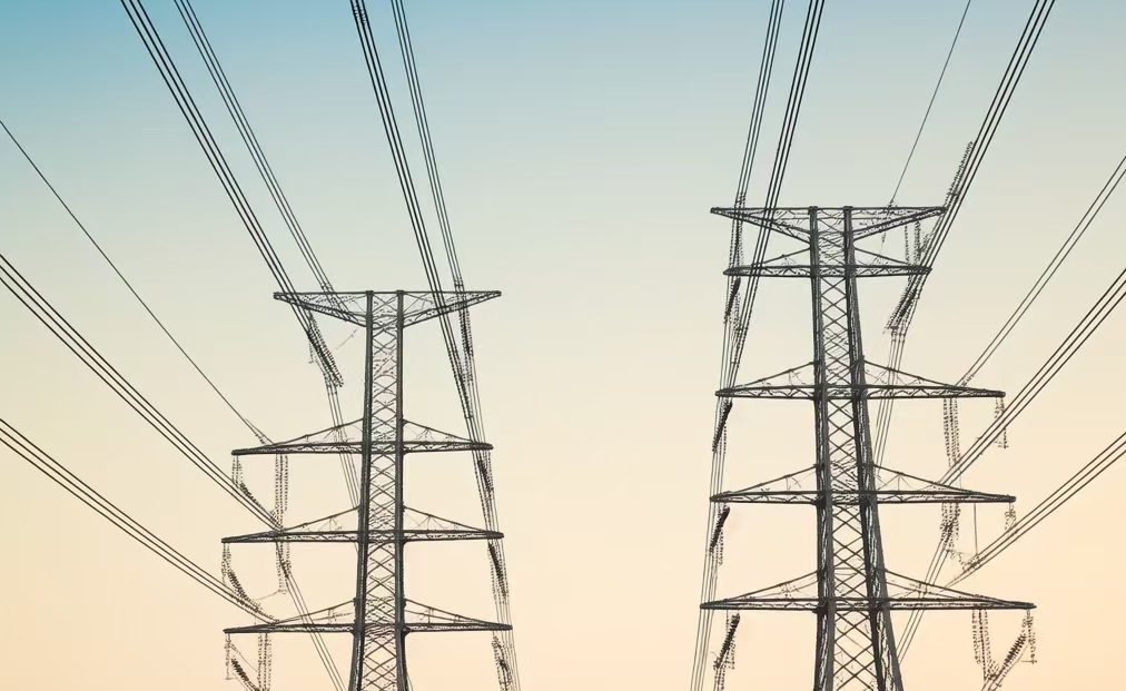
Electricity powers everything from lightbulbs to large factories, but it doesn’t flow at the same voltage everywhere. High voltage is used to transmit power efficiently, while low voltage is needed to run household appliances safely. So how does electricity adapt to these different needs? The answer lies in a transformer—a device that changes the voltage of alternating current (AC) electricity. Found in power plants, substations, laptops, and even your phone charger, transformers are one of the most essential and widely used components in any electrical system.
A transformer is an electrical device that changes the voltage level of alternating current (AC) by using electromagnetic induction between two or more wire coils wound around a magnetic core. It can either increase (step up) or decrease (step down) the voltage to suit the application, without any moving parts or direct electrical contact between the input and output circuits.
Transformers are vital for making electricity safe, efficient, and usable across different systems and devices.
Transformers change the voltage of alternating current electricity using electromagnetic induction.True
Transformers work on AC by inducing voltage changes through magnetic coupling between windings wrapped around a core.
Transformers convert electricity using moving mechanical parts and direct connections between input and output.False
Transformers have no moving parts and rely solely on magnetic fields to transfer energy without physical electrical contact.
Key Characteristics of a Transformer
| Feature | Explanation |
|---|---|
| Works with AC Power | Only alternating current creates the magnetic field changes needed for induction |
| No Moving Parts | Completely static device, which reduces wear and maintenance |
| Electromagnetic Induction | Transfers power via magnetic field from one coil (winding) to another |
| Changes Voltage | Raises or lowers AC voltage based on coil turn ratio |
| Electrical Isolation | Provides galvanic separation between circuits for safety |
Common Types of Transformers
| Type | Primary Function | Used In |
|---|---|---|
| Power Transformer | Step up/down voltage in power systems | Power plants, substations |
| Distribution Transformer | Deliver usable voltage to homes/businesses | Street poles, utility grids |
| Instrument Transformer | Measure current/voltage safely | Metering and protection in substations |
| Isolation Transformer | Electrically isolate equipment | Hospitals, labs, sensitive electronics |
| Low-Voltage Transformer | Power electronics and LED lighting | Doorbells, chargers, audio systems |
No matter the application, the core idea is the same: adjust voltage for safe and efficient use.
How Does a Transformer Work? (Simple Steps)
- AC current enters the primary coil, generating a changing magnetic field.
- The magnetic field passes through the transformer’s core, linking to the secondary coil.
- This field induces voltage in the secondary coil based on how many turns it has.
- The output voltage is either higher or lower than the input, depending on the coil ratio.
$$\frac{V_s}{V_p} = \frac{N_s}{N_p}$$
Where:
- $V_s$ = Secondary Voltage
- $V_p$ = Primary Voltage
- $N_s$, $N_p$ = Number of turns on each coil
Simple Real-World Examples
| Example | Input Voltage | Output Voltage | Transformer Function |
|---|---|---|---|
| Laptop Charger | 230V (AC) | 19V (DC via adapter) | Steps down for electronics use |
| Power Substation | 220kV | 33kV | Steps down for local distribution |
| Phone Charger | 230V | 5V USB | Built-in transformer + converter |
| Solar Power System | 48V (DC) | 220V (AC) | Inverter + transformer combination |
These examples show how transformers bridge the gap between high-voltage sources and low-voltage applications.
Why Transformers Matter
| Reason | Importance |
|---|---|
| Efficiency | Reduce energy loss in transmission |
| Safety | Deliver electricity at user-safe levels |
| Scalability | Allow centralized generation with decentralized usage |
| Versatility | Adapt to residential, industrial, and commercial needs |
| Reliability | Durable with minimal maintenance over decades |
Without transformers, electric power distribution as we know it would not exist.
What Specifically Defines a Power Transformer?
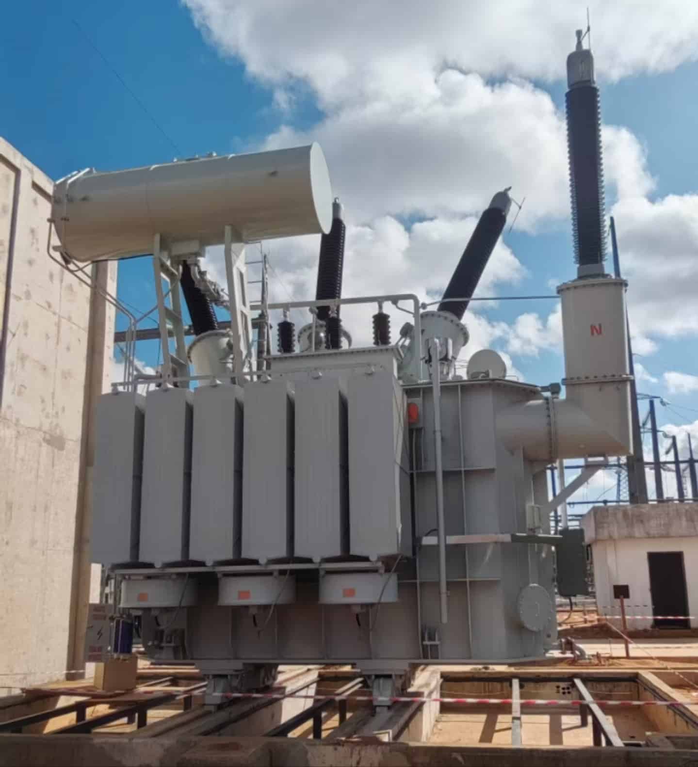
Not all transformers are created equal. In the vast world of electrical equipment, the power transformer stands out as a distinct class of transformer engineered for bulk energy transfer at high voltage levels. While distribution and instrument transformers serve critical roles, power transformers are the giants of the grid, enabling long-distance energy transmission between generation stations and distribution networks. Their size, voltage handling capacity, construction, and duty cycle clearly set them apart from other types.
A power transformer is a high-capacity electrical device specifically designed to transfer electrical energy between different voltage levels in the transmission segment of the power grid, typically operating above 33 kV and rated from several MVA to over 1000 MVA. It is defined by its high efficiency, full-load operation, robust insulation, and ability to step up or step down voltage between generation and distribution systems.
It’s not just a transformer—it’s the backbone of high-voltage energy infrastructure.
A power transformer is designed for high-voltage, high-capacity operation in the transmission segment of the power grid.True
Power transformers typically operate above 33 kV, often between 132 kV to 765 kV, and handle hundreds of megavolt-amperes (MVA).
Power transformers are small units meant for final voltage delivery to homes.False
That is the role of distribution transformers. Power transformers handle bulk voltage transitions far upstream in the grid.
Key Parameters That Define a Power Transformer
| Feature | Power Transformer Specification |
|---|---|
| Voltage Rating | Typically ≥ 33 kV (commonly 66, 132, 220, 400, or 765 kV) |
| Power Capacity | Usually ≥ 5 MVA up to 1000+ MVA |
| Location in Grid | Installed at generation switchyards or high-voltage substations |
| Cooling System | Oil Natural Air Natural (ONAN), ONAF, OFAF, OFWF |
| Duty Cycle | Operates at or near full load continuously |
| Tap Changer Type | Usually On-Load Tap Changer (OLTC) for voltage regulation |
| Efficiency Range | 98.5% to 99.3% |
| Impedance & Voltage Control | High short-circuit strength with adjustable tap settings |
Power transformers are precision-engineered to operate under full load for long durations with minimal efficiency loss.
Differentiation from Other Transformers
| Aspect | Power Transformer | Distribution Transformer | Instrument Transformer |
|---|---|---|---|
| Voltage Range | 66 kV to 765 kV | 11 kV to 400 V | Measurement-rated (e.g., 11kV / 110V) |
| Power Rating | 5 MVA to 1000+ MVA | 25 kVA to 2.5 MVA | Not for power transfer |
| Location | Generation plants, HV substations | Near load centers | Inside protection/control panels |
| Function | Voltage transition between grid tiers | Final step-down for consumer supply | Measuring current/voltage for metering |
| Load Profile | Operates near full load | Varies (partial to full load) | Operates with negligible current |
Typical Use Cases of Power Transformers
| Application | Transformer Specification |
|---|---|
| Step-Up at Power Plants | 11/22/33 kV → 220/400/765 kV |
| Grid Interconnection Point | 400 kV ↔ 220 kV or 132 kV |
| Regional Switching Station | 220 kV → 66/33 kV |
| Long-Distance Transmission | Enables low-loss power movement over 100+ km |
Every critical transmission junction uses at least one power transformer to enable voltage adaptation and grid stability.
Construction Features Unique to Power Transformers
| Component | Purpose in Power Transformers |
|---|---|
| Laminated CRGO Core | Minimizes eddy current and hysteresis loss |
| Large Winding Sections | Handles high current without overheating |
| Conservator Tank System | Allows oil expansion during load cycles |
| Buchholz Relay & PRD | Early warning system for internal faults |
| High Voltage Bushings | Withstand insulation stress at transmission voltages |
| Cooling Radiators or Pumps | Dissipate heat generated by copper and core losses |
These components make power transformers suitable for grid-scale voltage and power management.
Transformer Sizing and Efficiency in Context
| Transformer Size | Application | Typical Efficiency |
|---|---|---|
| 10 MVA | Regional step-down substation | \~98.6% |
| 100 MVA | State/national transmission interface | \~98.9% |
| 315 MVA | Large generation interconnection | \~99.2% |
| 765/400 kV class | Bulk power corridor distribution | \~99.3% |
Even with massive loads, losses are kept under 1.5%, demonstrating robust design.
How Do Power Transformers Differ from Distribution Transformers?
Though they share the same core principle—voltage transformation using electromagnetic induction—power transformers and distribution transformers are built for fundamentally different purposes in the electrical grid. From design and capacity to installation and function, these two transformer types play distinct roles in keeping power flowing efficiently and safely. Confusing them or misapplying one in place of the other can lead to inefficiencies, overloads, or even equipment failure. Understanding their differences is key for anyone involved in power infrastructure design, planning, or maintenance.
Power transformers differ from distribution transformers in terms of voltage rating, capacity, location in the grid, duty cycle, and design focus. Power transformers operate at high voltages (≥33 kV), handle large capacities (≥5 MVA), and are used in transmission networks for efficient bulk power transfer. Distribution transformers, on the other hand, operate at lower voltages (≤33 kV), typically below 2.5 MVA, and are installed near end users to step down voltage for local consumption.
Each transformer type is engineered for its specific position and purpose within the power delivery system.
Power transformers and distribution transformers serve different functions in the power grid based on voltage level, capacity, and location.True
Power transformers operate in the transmission segment to handle high voltage and bulk power, while distribution transformers step voltage down for consumer use.
Distribution transformers and power transformers are the same and can be used interchangeably.False
Their designs, ratings, and roles in the grid are not interchangeable; using one in place of the other can result in poor efficiency or failure.
Side-by-Side Comparison: Power vs. Distribution Transformers
| Feature | Power Transformer | Distribution Transformer |
|---|---|---|
| Voltage Range | ≥33 kV (Common: 132/220/400/765 kV) | ≤33 kV (Common: 11 kV / 400 V) |
| Power Rating | 5 MVA – 1000+ MVA | 25 kVA – 2.5 MVA |
| Location in Grid | Transmission substations and generation switchyards | Near homes, businesses, or commercial buildings |
| Function | Step-up or step-down in transmission grid | Final voltage reduction for local consumption |
| Duty Cycle | Operates near full load continuously | Operates at variable or partial load |
| Tap Changer | OLTC (On-Load Tap Changer) | DETC (De-energized Tap Changer) or none |
| Cooling System | ONAN, ONAF, OFAF (active cooling) | ONAN (mostly passive air/oil cooling) |
| Efficiency Focus | Maximized under full load | Optimized for minimal no-load losses |
| Size and Cost | Very large, expensive, requires infrastructure | Compact, cost-effective, can be pole/pad mounted |
| Installation | Fixed in high-voltage yards with civil works | Mounted on poles, pads, or inside buildings |
Visual Illustration: Grid Positioning
| Power Transformer | Distribution Transformer |
|---|---|
| Power Plant → Step-up to 220kV | Local substation → 11kV to 400V |
| Transmission Line → 400kV to 132kV | Utility pole → 11kV to 230V single-phase |
| Bulk transmission → Regional grid | Office/hospital → 11kV to 400/230V |
Power transformers handle national-scale flow, while distribution transformers serve neighborhoods and individual buildings.
Design Differences
| Parameter | Power Transformer | Distribution Transformer |
|---|---|---|
| Core Design | Large CRGO laminated core | Compact core for space efficiency |
| Winding Material | High-grade copper with large cross-section | Copper or aluminum, often compact windings |
| Insulation Level | Heavy-duty (Class A/B/F) for HV use | Medium insulation (often Class A or F) |
| Protection Features | Full relay, Buchholz, gas, temp sensors | Basic fuse/breaker protection |
Power transformers prioritize MVA performance, while distribution units prioritize simplicity and reliability.
Real-World Application Examples
| Scenario | Transformer Type Used | Why It’s Appropriate |
|---|---|---|
| 220kV to 132kV interconnection | Power Transformer (e.g., 315 MVA) | Required to handle bulk energy with minimal loss |
| Substation to commercial complex | Distribution Transformer (e.g., 1 MVA) | Matches building load and voltage need |
| Solar farm grid injection at 33kV | Pad-mounted Power Transformer | Used to step up inverter output to grid level |
| Street pole feeding residential homes | Pole-mounted Distribution Transformer | Provides 400/230V for end-user safety |
Efficiency and Load Considerations
| Condition | Power Transformer | Distribution Transformer |
|---|---|---|
| Best Efficiency Point | Near 100% full load | 50–70% load range |
| No-Load Loss Concern | Less critical | Highly important for 24/7 energization |
| Thermal Behavior | Continuous cooling needed | Occasional load spikes allowed |
Where Are Power Transformers Typically Used Compared to General Transformers?

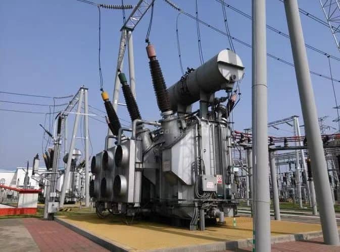
Electricity doesn’t flow from generation plants to end-users through a single kind of transformer—it takes a network of specialized transformers, each performing a different role at different points in the system. Among these, power transformers are specifically engineered for high-voltage, high-capacity applications and differ in purpose from more general transformers used in electronics, buildings, or small industrial equipment. Their use is strategic and location-specific, forming the backbone of electrical transmission systems.
Power transformers are typically used in high-voltage transmission and generation systems, such as substations and power plants, where they transfer bulk electricity at voltages above 33 kV. In contrast, general transformers are used in a wide range of lower-voltage applications, including distribution systems, industrial plants, buildings, medical equipment, and electronic devices. Each is optimized for the demands and environment of its intended use.
Understanding where these transformer types are deployed helps clarify how electricity flows from source to socket.
Power transformers are used in transmission networks, while general transformers serve a variety of applications from distribution to electronics.True
Power transformers operate at high voltages for grid-level energy transfer, whereas general transformers operate at medium or low voltages in commercial, residential, and specialized applications.
All transformers, including those used in electronics, are classified as power transformers.False
Power transformers are a specific type used in transmission systems, while general transformers include distribution, instrument, isolation, and low-voltage transformers.
Where Power Transformers Are Typically Used
| Location | Voltage Levels | Function |
|---|---|---|
| Generation Plants | 11–25kV stepped up to 132–765kV | Step-up transformer for long-distance transmission |
| Transmission Substations | 220–400–765kV | Interconnect and regulate regional HV grids |
| Switchyards | 220kV / 400kV | Transition points for grid intertie connections |
| Large Renewable Installations | 33–132kV | Integrate solar/wind energy into transmission grid |
| Grid Interconnection Points | 400kV ↔ 220kV ↔ 132kV | Balance national or regional transmission loads |
Power transformers enable low-loss transmission of large energy volumes across long distances.
Where General Transformers Are Typically Used
| Transformer Type | Common Application | Voltage Range |
|---|---|---|
| Distribution Transformer | Urban and rural neighborhoods | 11kV → 400/230V |
| Dry-Type Transformer | Commercial buildings, malls, hospitals | 11kV → 400/230V |
| Isolation Transformer | Medical devices, labs, audio systems | 230V → 230V |
| Instrument Transformer | Grid monitoring and protection systems | 33kV / 132kV → 110V / 5A |
| Control Transformer | Industrial automation panels | 400V → 24V / 12V |
| Electronic Transformer | Chargers, TVs, laptops, LED lighting | 230V → 5V / 19V |
General transformers are diverse and found in nearly every electrical or electronic system.
Comparative Table: Deployment and Purpose
| Category | Power Transformers | General Transformers |
|---|---|---|
| Voltage Range | 66–765 kV | ≤ 33 kV (often 230V–400V for end use) |
| Power Rating | 5–1000+ MVA | 0.5 VA – 2.5 MVA (typical general use) |
| Location in Grid | Transmission substations, generation plants | Distribution lines, buildings, devices |
| Use Case | Step-up/down at transmission level | Power delivery, equipment protection, control |
| Cooling System | Oil-based (ONAN, ONAF, OFAF) | Air-cooled, dry-type, oil-immersed (low volume) |
| Operational Profile | 100% load, continuous duty | Varies—intermittent, low duty, or full load |
Real-World Application Scenarios
Power Transformer Example:
- Location: Thermal power plant switchyard
- Function: Steps up 22kV generator voltage to 400kV
- Rating: 250 MVA, oil-immersed, OLTC-equipped
- Installed in: National transmission corridor
General Transformer Example:
- Location: Hospital operating theater
- Function: Isolates and stabilizes voltage for medical equipment
- Rating: 230V → 230V, 5 kVA
- Installed in: Indoor wall-mounted cabinet with fire protection
System Role Perspective
| System Level | Transformer Type Used | Purpose |
|---|---|---|
| Power Generation | Power Transformer | Voltage step-up for transmission |
| Transmission | Power Transformer | Long-distance, low-loss transfer |
| Distribution Substation | Distribution Transformer | Step-down for regional grids |
| Commercial Buildings | Dry-Type or Control Transformer | Internal power and automation circuits |
| Home Electronics | Low-Voltage Transformer | Converts 230V to 12V, 5V, etc. |
| Metering Panels | Instrument Transformer (CTs, VTs) | Accurate measurement and protection |
Summary of Key Differences in Use
| Aspect | Power Transformer | General Transformers |
|---|---|---|
| Scale | Utility-scale power handling | Consumer, commercial, or industrial level |
| Installation Type | Outdoor, grid-tied, heavy-duty | Indoor/outdoor, modular, or integrated systems |
| Grid Position | Between power plant and grid backbone | Near end-users or integrated in devices |
| Design Purpose | High-efficiency, high-load, HV use | Versatile use at low/medium voltage |
What Are the Voltage and Capacity Ranges of Power Transformers vs. Other Types?
Transformers come in many forms, each tailored for a specific role in the electrical ecosystem. Whether transmitting power across continents or stepping voltage down for electronic devices, each transformer type operates within defined voltage and capacity limits. The voltage and MVA/kVA range of a transformer determines its suitability for transmission, distribution, industrial, or electronic applications. Understanding these ranges helps engineers and planners choose the right equipment for the right task—from megawatt-level grid interconnection to milliwatt-level device powering.
Power transformers operate in the highest voltage and capacity ranges, typically from 66 kV to 765 kV and 5 MVA to over 1000 MVA, making them essential for long-distance bulk power transfer. In contrast, distribution transformers work between 400 V and 33 kV with capacities ranging from 25 kVA to 2.5 MVA. Other types such as isolation, instrument, and control transformers operate at much lower voltages (often below 1 kV) and capacities, usually under 100 kVA.
Each transformer type is engineered for a specific voltage tier and load profile in the electrical infrastructure.
Power transformers are designed for high-voltage and high-capacity operations in the transmission grid, while other types like distribution or instrument transformers handle lower voltage and capacity tasks.True
Power transformers commonly operate above 66 kV and 5 MVA, while distribution and other transformers function in lower voltage and capacity ranges for local and specialized applications.
All transformers, regardless of type, operate within the same voltage and capacity range.False
Transformers are designed for specific use cases, and their voltage and power handling capabilities vary significantly across types.
Voltage and Capacity Ranges by Transformer Type
| Transformer Type | Typical Voltage Range | Typical Capacity Range | Primary Application |
|---|---|---|---|
| Power Transformer | 66 kV – 765 kV | 5 MVA – 1200+ MVA | Transmission and grid interconnection |
| Distribution Transformer | 400 V – 33 kV | 25 kVA – 2.5 MVA | Local voltage delivery (residential/commercial) |
| Instrument Transformer | 11 kV – 400 kV (input), stepped down to 110V/5A | < 10 kVA | Measurement and protection systems |
| Isolation Transformer | 230 V – 480 V (typically) | 0.5 kVA – 100 kVA | Electrical isolation in medical/industrial use |
| Control Transformer | 120 V – 600 V | 0.05 kVA – 10 kVA | Machine panels and automation control |
| Electronic Transformer | 5 V – 230 V | Few VA – 1 kVA | Consumer electronics and chargers |
Power transformers dominate the top tier of voltage and capacity, while other types serve low-voltage, specialized, or localized needs.
Graph: Voltage vs Capacity Ranges by Transformer Type
| Transformer Type | Voltage Band | Capacity Band |
|---|---|---|
| Power Transformer | 66 kV – 765 kV | 5 MVA – 1200 MVA+ |
| Distribution Transformer | 400 V – 33 kV | 25 kVA – 2500 kVA |
| Instrument Transformer | 11 kV – 400 kV → 110 V | < 10 kVA |
| Isolation Transformer | 230 V – 480 V | 0.5 – 100 kVA |
| Control Transformer | 120 V – 600 V | 50 VA – 10 kVA |
| Electronic Transformer | 5 V – 230 V | 1 VA – 1 kVA |
Use Case Examples Based on Capacity and Voltage
| Application | Transformer Type | Voltage Level | Power Rating |
|---|---|---|---|
| National Grid Interconnection | Power Transformer | 400 kV / 220 kV | 315–1000 MVA |
| Regional Distribution Substation | Distribution Transformer | 33 kV / 11 kV | 1–2.5 MVA |
| Hospital Equipment Protection | Isolation Transformer | 230 V → 230 V | 10–50 kVA |
| Factory Control Panel | Control Transformer | 400 V → 24 V | 1–5 kVA |
| Smart Phone Charger | Electronic Transformer | 230 V → 5 V | 10–100 VA |
| Utility Metering System | Instrument Transformer | 132 kV → 110 V | \~2–5 kVA (measurement) |
Selecting the right transformer type based on load profile, safety needs, and voltage level is essential for system reliability.
Capacity-Voltage Matrix
| Capacity Range | Voltage Range | Typical Transformer Types |
|---|---|---|
| 0.01 – 1 kVA | 5 V – 230 V | Electronic, control transformers |
| 1 – 10 kVA | 120 V – 600 V | Control, isolation transformers |
| 10 – 100 kVA | 230 V – 11 kV | Isolation, distribution transformers |
| 100 – 2500 kVA | 11 kV – 33 kV | Distribution transformers |
| 2.5 MVA – 1200+ MVA | 66 kV – 765 kV | Power transformers (step-up/down for grid transmission) |
Engineering Insights
- Power Transformers must withstand high dielectric stress, have advanced cooling (ONAF, OFAF), and include tap changers for grid voltage control.
- Distribution Transformers are optimized for energy efficiency at partial loads, often operating 24/7 with minimal no-load loss.
- Instrument Transformers prioritize accuracy and safety, stepping down voltages for metering/relays without energy transfer.
- Isolation Transformers prevent ground loops and electrical noise, critical in sensitive systems.
- Electronic Transformers often use switching and compact ferrite cores for efficiency and space savings.
Why Does the Distinction Between Transformer Types Matter in Practice?

In a world powered by electricity, choosing the right transformer isn’t just a technical detail—it’s a critical decision that affects safety, efficiency, cost, and system reliability. With a wide range of transformer types available—each designed for a distinct purpose—mistaking one for another can result in equipment damage, energy waste, or even safety hazards. That’s why understanding and maintaining a clear distinction between transformer types is essential in practical engineering, operations, and procurement.
The distinction between transformer types matters because each is specifically designed to operate at certain voltage levels, handle specific power capacities, and serve different functions—such as transmission, distribution, isolation, measurement, or control. Using the wrong transformer type can result in inefficiency, system failure, increased operational costs, or safety violations. Proper classification ensures optimal performance, safety, compliance, and longevity in real-world applications.
From a national grid to a laptop charger, transformers aren’t interchangeable—they’re precision-engineered for purpose.
Transformer types must be correctly matched to their function and application to ensure safe and efficient performance.True
Power, distribution, isolation, and instrument transformers each serve unique roles and cannot be substituted without compromising safety or functionality.
Any transformer can be used in any electrical setup as long as it matches the voltage.False
Matching voltage is only part of the equation; transformer type determines capacity, insulation, cooling, safety features, and compatibility with system demands.
Practical Differences That Make Classification Crucial
| Parameter | Why It Matters |
|---|---|
| Voltage Range | Incorrect voltage class can lead to insulation breakdown or unsafe operation |
| Power Rating (kVA/MVA) | Oversized = inefficiency; undersized = overheating and failure |
| Cooling Type | Inadequate cooling in wrong application causes thermal runaway |
| Duty Cycle | Transformers designed for full load may not perform well under fluctuating load |
| Insulation System | Mismatch can result in arcing, dielectric failure, or fire hazards |
| Use Environment | Indoor, outdoor, marine, medical, or industrial transformers differ in enclosures and protection levels |
| Regulatory Compliance | Incorrect transformer class may violate IEC/UL/ANSI codes |
Real-World Scenarios Where Distinctions Matter
1. Substation Using a Distribution Transformer Instead of a Power Transformer
- ❌ Voltage insulation fails at 132kV
- 🔥 Core overheats due to undersized windings
- ⚠ Grid instability, blackout risk
2. Using a Power Transformer for a Small Building
- ⚡ Oversized unit consumes excess no-load power
- 💸 Unnecessary capital and maintenance expense
- ❌ No tap flexibility for low-voltage loads
3. Medical Equipment Using a Distribution Transformer Instead of an Isolation Transformer
- 🔌 Lack of galvanic isolation = ground loops
- 🏥 High EMI = malfunction in sensitive diagnostics
- 🚫 Non-compliance with health and safety standards
4. Using an Electronic Transformer for Industrial Motor Control
- 💥 Not designed for inductive/reactive loads
- 🔄 Fails under surge or harmonic distortion
- ❌ Shortened transformer life, equipment risk
Purpose-Matched Performance Table
| Transformer Type | Primary Use | Why Type Matters |
|---|---|---|
| Power Transformer | Transmission grid interface | Engineered for HV insulation, load regulation, and continuous duty |
| Distribution Transformer | Deliver power to consumers | Designed for 24/7 energization, partial loading, and compact layout |
| Isolation Transformer | Eliminate ground loops | Provides galvanic separation for noise and shock protection |
| Instrument Transformer | Metering/protection | High accuracy, limited burden, and system protection integration |
| Control Transformer | Industrial panels | Supports frequent switching, voltage dips, and short-duration surges |
| Electronic Transformer | Consumer devices | High-frequency operation and compact low-power delivery |
Engineering and Safety Implications
| Incorrect Use of Type | Potential Consequences |
|---|---|
| Using control transformer for power supply | Voltage drop under load, tripping relays |
| Power transformer in distribution role | High no-load loss, poor voltage regulation |
| Distribution transformer in hospital | No EMI shielding, safety risk |
| Instrument transformer in power circuit | Dangerous overload, inaccurate metering |
Choosing the right transformer type is not just technical—it’s mission-critical.
Cost, Efficiency, and Maintenance Considerations
| Factor | Properly Matched Transformer | Improperly Matched Transformer |
|---|---|---|
| Initial Cost | Justified investment | Over or under-spec = wasted spending |
| Energy Efficiency | High efficiency, low loss | Excessive core/copper losses |
| Operational Lifespan | 25–40 years | Premature failure due to misuse |
| Maintenance | Predictable, low intervention | Frequent repair, higher OPEX |
Conclusion
In short, all power transformers are transformers, but not all transformers are power transformers. A transformer is a general term for a device that transfers electrical energy between circuits via electromagnetic induction. A power transformer is a specific type designed to operate at higher voltage and power levels, commonly used in transmission networks. Understanding their roles helps ensure proper selection and optimal system performance across various electrical applications.
FAQ
Q1: What is the main difference between a transformer and a power transformer?
A1: The term “transformer” is a general category for any device that transfers electrical energy between circuits by electromagnetic induction. A power transformer is a specific type of transformer designed for high-voltage transmission and large power capacity in substations and power plants.
Q2: How do their voltage levels differ?
A2: Power transformers typically operate at high voltages (above 33kV) and are used in transmission networks.
General transformers include all types, from low-voltage (e.g., 12V adapters) to medium and high-voltage units used across various applications.
Q3: Where are power transformers used compared to general transformers?
A3: Power transformers are found in generating stations and transmission substations, where they step voltage up or down for bulk energy movement.
General transformers are used in a wide range of applications including residential (e.g., doorbells), industrial machinery, electronic devices, and instrumentation.
Q4: What about operating load conditions?
A4: Power transformers are optimized for constant full-load operation and high efficiency.
Many general-purpose transformers, like distribution transformers, are designed for variable loads and operate efficiently even at partial loads.
Q5: Are there structural or design differences?
A5: Yes. Power transformers are typically larger, have advanced cooling systems (oil-immersed or forced air), and tap changers for voltage regulation. General transformers may be compact, air-cooled, and simpler in construction, tailored to specific use cases.
References
"Difference Between Transformer and Power Transformer" – https://www.transformertech.com/transformer-vs-power-transformer
"Transformer Types and Their Differences" – https://www.electrical4u.com/difference-between-transformer-and-power-transformer
"Power Transformers vs. General Transformers" – https://www.powermag.com/transformer-types-compared
"How Power Transformers Differ from Distribution Units" – https://www.sciencedirect.com/transformer-comparison
"Smart Grid News: Choosing the Right Transformer Type" – https://www.smartgridnews.com/transformer-type-differences
"ResearchGate: Classification of Transformers by Function" – https://www.researchgate.net/transformer-type-study
"Energy Central: Transformer Applications and Variations" – https://www.energycentral.com/c/ee/transformer-vs-power-transformer
"PowerGrid: Guide to Transformer Categories" – https://www.powergrid.com/transformer-type-guide