In the vast world of electrical engineering, the term "power transformer" refers to a specific type of transformer designed for high-voltage, high-capacity applications. These transformers are essential components in the transmission and distribution of electrical energy across long distances. But what exactly defines a transformer as a power transformer?
What Is the Basic Definition of a Power Transformer?
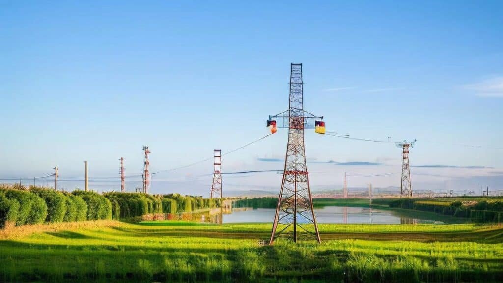
Electricity travels a long journey from power plants to homes and industries—and voltage transformation is essential to make that journey efficient and safe. One of the most crucial components enabling this is the power transformer. While it may look like a big metal box in a substation, its role is both foundational and vital in any electrical power system. Without it, high-voltage transmission and safe energy delivery would be impossible.
A power transformer is a static electrical device used in high-voltage transmission networks to increase (step-up) or decrease (step-down) the voltage of alternating current (AC) without changing the frequency. It operates at voltage levels above 33 kV and power ratings typically above 5 MVA, making it essential for transferring electrical energy over long distances with minimal loss.
It is a key enabler of large-scale energy movement across regions, utilities, and industrial grids.
A power transformer is used to step up or step down voltage in high-voltage transmission systems.True
It enables efficient power transfer by adapting voltage levels to reduce current and minimize energy losses over long distances.
A power transformer is a low-voltage device used only in small household systems.False
Power transformers are designed for high-voltage, high-capacity transmission systems, unlike low-voltage distribution transformers used near consumers.
Key Characteristics of a Power Transformer
| Feature | Description |
|---|---|
| Voltage Range | Typically 66 kV – 765 kV |
| Power Rating | 5 MVA to 1200+ MVA |
| Installation Location | Found in generation stations, transmission substations, and grid tie points |
| Cooling System | Oil-based (ONAN, ONAF, OFAF), sometimes with forced-air or water |
| Core Function | Uses electromagnetic induction between coils to change AC voltage |
Role in the Power Grid
| Grid Stage | Power Transformer Function |
|---|---|
| Generation Plant | Steps up voltage (e.g., 11 kV → 400 kV) for transmission |
| Transmission Substation | Interconnects regional grids (e.g., 400 ↔ 220 kV) |
| Grid Entry Point | Steps down voltage (e.g., 220 kV → 33 kV) for distribution |
These transformers are always part of the high-voltage side of the electrical infrastructure.
Basic Working Principle
- AC current enters the primary winding.
- A magnetic field forms in the transformer core.
- This field induces voltage in the secondary winding based on the turns ratio.
- The result is a different voltage level at the output, but the same power (minus minor losses).
$$\frac{V_s}{V_p} = \frac{N_s}{N_p}$$
Where:
- $V_s$ = Secondary voltage
- $V_p$ = Primary voltage
- $N_s$, $N_p$ = Number of coil turns
Power vs Distribution Transformers (Quick Distinction)
| Aspect | Power Transformer | Distribution Transformer |
|---|---|---|
| Voltage | >33 kV | <33 kV |
| Location | Power stations, transmission substations | Near end-users (buildings, streets) |
| Power Capacity | 5–1000+ MVA | 25 kVA – 2.5 MVA |
| Function | Grid-scale voltage transformation | Final step-down for consumer supply |
Real Example
- Unit: 250 MVA, 400/220 kV, ONAN/ONAF cooled
- Application: Interconnects two regional transmission networks
- Efficiency: >99% under full load
- Cooling: Oil-immersed with 12 radiator banks and 8 axial fans
- Monitoring: Equipped with OLTC, DGA, and SCADA integration
This transformer ensures grid stability across hundreds of kilometers and millions of users.
How Does a Power Transformer Differ from a Distribution Transformer?
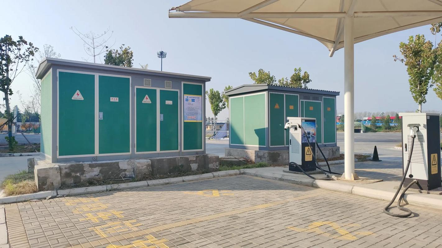
When planning or maintaining an electrical power system, it's crucial to understand that not all transformers serve the same purpose. Power transformers and distribution transformers are both vital in the energy supply chain, yet they function at very different points and scales within the grid. Using one in place of the other can lead to inefficiency, premature failure, or even safety hazards. Their differences lie in their voltage levels, power ratings, design philosophy, and operating conditions.
A power transformer is a high-voltage, high-capacity device used in transmission systems to step up or step down voltages (typically above 33 kV) for bulk energy transfer, whereas a distribution transformer operates at lower voltages (≤33 kV) and supplies electricity directly to end-users. Power transformers are designed for full-load efficiency and continuous operation, while distribution transformers are optimized for partial loads and energy efficiency in local networks.
Each type of transformer is built for a specific purpose, and understanding this distinction ensures safe, efficient grid performance.
Power transformers are designed for transmission systems and operate at high voltage, while distribution transformers serve lower-voltage end-use delivery.True
Their construction, capacity, and voltage ratings are tailored to different parts of the power grid.
Power transformers and distribution transformers are interchangeable devices with similar designs and functions.False
Each transformer type serves a specific grid level and cannot be swapped without compromising system performance or safety.
Technical Comparison: Power vs Distribution Transformers
| Parameter | Power Transformer | Distribution Transformer |
|---|---|---|
| Voltage Range | ≥66 kV to 765 kV | 11 kV to 400/230 V |
| Power Rating | 5 MVA – 1200+ MVA | 25 kVA – 2500 kVA |
| Grid Location | Generation and transmission substations | Near homes, businesses, or local grids |
| Duty Cycle | Operates at or near full load continuously | Varies—often under partial load |
| Efficiency Focus | Optimized for full-load efficiency | Optimized for minimal no-load loss |
| Cooling Type | Oil-immersed with radiators/fans/pumps | Oil-immersed or dry-type, passive cooling |
| Tap Changer | On-load tap changer (OLTC) for real-time voltage regulation | No tap or de-energized tap changer (DETC) |
| Installation | Fixed to foundation in substations | Pole-mounted, pad-mounted, or indoor |
| Size and Weight | Very large (100+ tons typical) | Small to medium (100–3000 kg) |
System Role Illustration
| Stage in Grid | Transformer Type | Voltage Transition |
|---|---|---|
| Generation Plant | Power Transformer | 11 kV → 220/400 kV |
| Transmission Substation | Power Transformer | 400 kV → 132/66 kV |
| Distribution Substation | Distribution Transformer | 33/11 kV → 400/230 V |
| End-User (Home/Factory) | Distribution Transformer | 11 kV → 400/230 V |
Power transformers handle bulk electricity transport, while distribution transformers ensure usable voltage at the point of use.
Design Philosophy Differences
| Design Element | Power Transformer | Distribution Transformer |
|---|---|---|
| Core Material & Size | Large CRGO core for high flux handling | Compact core optimized for 24/7 energization |
| Winding Structure | Heavier, thermally reinforced | Compact, simpler construction |
| Insulation Requirements | High dielectric strength for HV applications | Medium insulation (often Class A or B) |
| Protection Systems | Advanced relays, Buchholz relay, PRDs | Basic protection: fuses, surge arresters |
| Monitoring Features | RTDs, DGA sensors, SCADA-ready | Basic thermal indicators or none |
Efficiency and Operating Profile
| Load Condition | Power Transformer | Distribution Transformer |
|---|---|---|
| At Full Load | Peak efficiency (>98.5%) | Slight drop due to higher copper losses |
| At Light Load | Lower efficiency due to core loss | Higher efficiency—designed for this |
| Loss Management | Accepts core loss for load capacity | Minimizes no-load losses |
Each transformer type is optimized for different load behaviors and duty cycles.
Cost and Maintenance Considerations
| Aspect | Power Transformer | Distribution Transformer |
|---|---|---|
| Initial Cost | High (\$300k to \$2M+) | Low to moderate (\$2k–\$50k) |
| Maintenance Frequency | Regular oil, tap, and relay servicing | Minimal maintenance, simpler setup |
| Spare Availability | Made-to-order | Off-the-shelf in many cases |
Cost reflects both complexity and capacity, aligned with grid-scale vs. localized needs.
Real-World Example Comparison
| Transformer | 250 MVA Power Transformer | 500 kVA Distribution Transformer |
|---|---|---|
| Voltage Rating | 400/220 kV | 11/0.4 kV |
| Weight (including oil) | \~200 tons | \~800 kg |
| Footprint | 7.5 m × 4 m × 5 m | 1.2 m × 0.8 m × 1.5 m |
| Cooling Type | ONAF with radiator and fans | ONAN (natural air cooling) |
| Application | Substation grid interconnection | Power supply to small commercial area |
What Are the Typical Voltage and Power Ratings for Power Transformers?
Power transformers are built for strength. They serve as the primary voltage regulators in transmission systems, stepping up voltage for long-distance travel and stepping it down for distribution. Their effectiveness and suitability in any application—from a 66 kV substation to a 765 kV national corridor—depend largely on two critical specifications: voltage rating and power rating (MVA). These parameters define not just performance but also the size, cost, cooling needs, and installation infrastructure.
Typical power transformers operate at voltage levels ranging from 66 kV to 765 kV and power ratings from 5 MVA up to 1200 MVA. Their exact rating is selected based on the role in the grid—generation step-up, transmission intertie, or grid-level distribution. Higher voltage and power ratings are used to reduce current, minimize I²R losses, and ensure efficient long-distance energy transmission.
These rating ranges are governed by international standards (IEC, IEEE) and utility design practices.
Power transformers are rated for high voltage (66–765 kV) and high power (5–1200+ MVA) to enable grid-scale electricity transmission.True
They are designed to operate under high electrical stress and deliver megawatt-level energy with minimal loss.
Power transformers usually operate at low voltage levels like 11 kV or below.False
Such voltage levels are typical for distribution transformers, not power-class transformers.
Typical Voltage Ratings for Power Transformers
| Voltage Level (kV) | Application Area |
|---|---|
| 66 kV – 132 kV | Regional transmission substations, grid interface |
| 220 kV – 275 kV | National or interstate HV transmission |
| 330 kV – 400 kV | Backbone transmission corridors |
| 500 kV – 765 kV | Ultra-high voltage (UHV) for cross-country grids |
| Step-Up from Generator | Commonly 11, 13.8, or 22 kV → 132–400 kV |
Voltage ratings are typically standardized to match grid configuration and regional utility protocols.
Typical Power (MVA) Ratings by Application
| Transformer Role | Power Rating Range (MVA) | Common Example Ratings |
|---|---|---|
| Small Substation or Collector | 5 – 40 MVA | 10, 25, 31.5, 40 MVA |
| Medium Regional Grid Step-Down | 50 – 125 MVA | 63, 100, 125 MVA |
| Transmission Grid Intertie | 160 – 315 MVA | 200, 250, 315 MVA |
| UHV or Bulk Corridor | 400 – 1200+ MVA | 500, 630, 1000 MVA |
| Renewable Integration Step-Up | 10 – 125 MVA | 20, 40, 100 MVA |
Higher MVA capacity reduces voltage drop and heating under large load flows—critical for national grid reliability.
Voltage-to-MVA Mapping Table (Practical Overview)
| High Voltage Side (kV) | Low Voltage Side (kV) | Typical MVA Range | Usage Type |
|---|---|---|---|
| 400 | 220 | 250 – 630 | Transmission interconnection |
| 220 | 132 | 100 – 315 | Grid step-down |
| 132 | 33 | 25 – 100 | Distribution substation interface |
| 33 | 11 | 5 – 40 | Industrial zone / renewable step-down |
| 22 | 220 or 400 | 40 – 100 | Generation step-up transformer |
These voltage pairs represent common transformer designs in grid architectures across the world.
Real-World Examples
| Project | Transformer Rating | Voltage Levels | Application |
|---|---|---|---|
| National Grid Interconnect | 500 MVA | 400/220 kV | Long-distance transmission |
| Regional Switching Station | 160 MVA | 220/132 kV | Sub-transmission to distribution interface |
| Wind Farm Step-Up | 40 MVA | 33/132 kV | Collector to transmission integration |
| Thermal Plant Output | 315 MVA | 22/400 kV | Generator step-up |
Ratings are selected based on system load, power flow, short-circuit level, and future scalability.
Rating Standards and Classification
| Standard | Defines Rating Criteria For |
|---|---|
| IEC 60076-1 | General transformer ratings, voltage class, MVA levels |
| IEEE C57.12.00 | US standard for ratings, impedance, and temperature rise |
| IS 2026 (India) | Rating, cooling class, dielectric levels for power transformers |
All ratings are based on ambient temperature, altitude, and duty cycle assumptions set by these standards.
Design Considerations by Rating
| Parameter | Effect of Higher Ratings |
|---|---|
| Winding Cross Section | Increases to carry higher current without overheating |
| Core Size | Enlarged to handle higher magnetic flux |
| Cooling Requirement | Moves from ONAN to ONAF or OFAF (forced oil and air) |
| Protection Complexity | More protection zones, faster relays, stronger mechanical bracing |
| Transportation & Size | Requires multi-axle transport, cranes, and larger foundations |
Larger ratings require more sophisticated design, site preparation, and operational management.
Where Are Power Transformers Commonly Used?
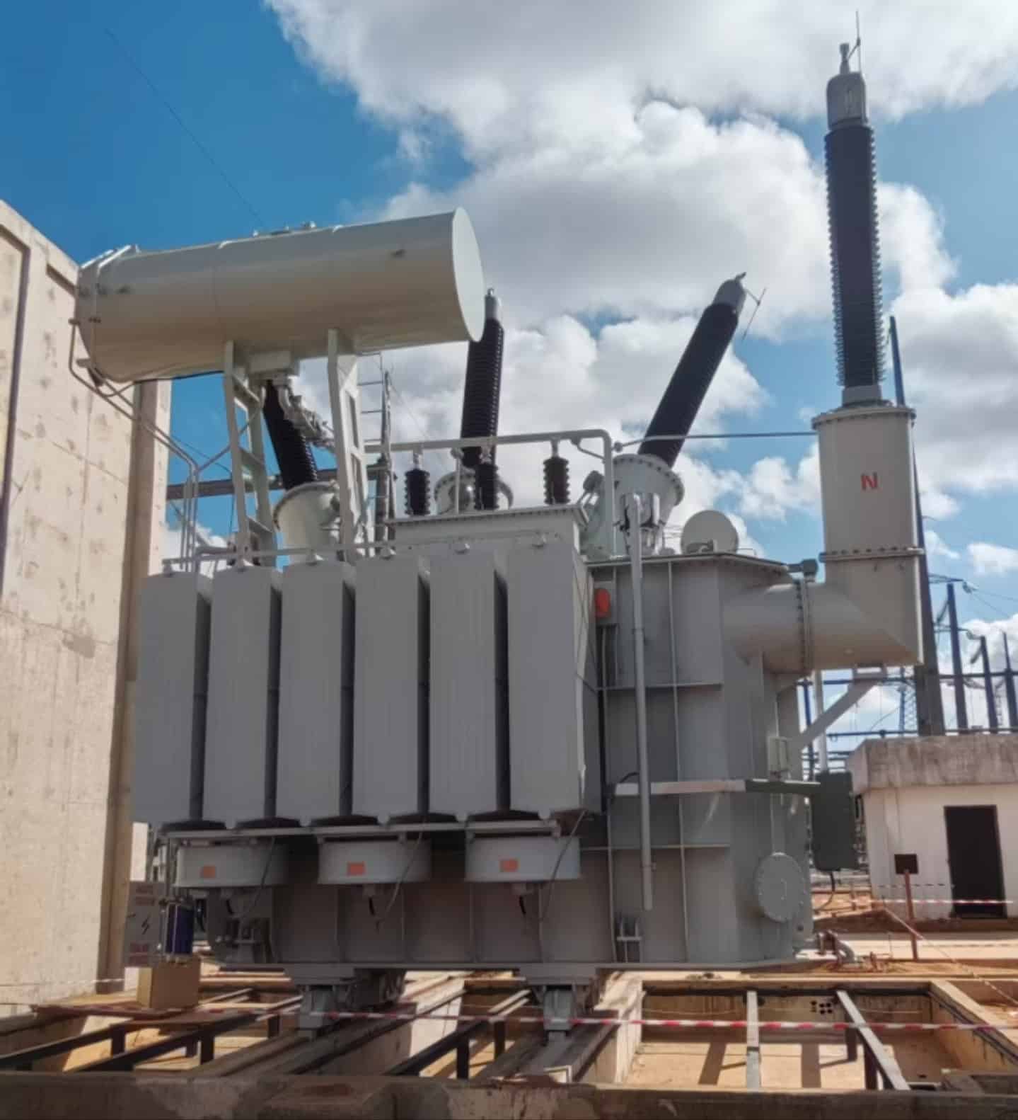
Power transformers are massive, high-voltage machines that serve as the backbone of electrical infrastructure. While they’re often hidden behind substation fences or inside utility switchyards, they are quietly performing one of the most essential roles in global energy systems: transforming voltage to efficiently transmit massive amounts of power over long distances. But their function isn’t limited to transmission—they’re used in every major stage of the power network, from generation to industrial application. Understanding where these devices are installed helps planners, engineers, and investors optimize power system design.
Power transformers are commonly used at generation switchyards to step up voltage, in transmission substations to interconnect and step down voltage for distribution, in grid interconnection points to balance regions, and in industrial plants to power large loads. They are also used in renewable energy collector stations to integrate wind and solar output into the grid. Their role is to move electricity efficiently at high voltage, across long distances and heavy loads.
Wherever bulk energy flows need to be controlled, conditioned, or redistributed—power transformers are at work.
Power transformers are used at key points in the transmission and generation parts of the power grid.True
They step up voltage for transmission, interconnect high-voltage systems, and step down voltage for distribution at grid-scale.
Power transformers are used mainly for home appliances and small-scale applications.False
Those are distribution or electronic transformers. Power transformers serve high-voltage, high-power grid and industrial applications.
Primary Locations Where Power Transformers Are Used
| Location | Typical Voltage Range | Power Rating (MVA) | Function |
|---|---|---|---|
| Power Generation Plants | 11–25 kV (input), 132–400 kV (output) | 50–315+ MVA | Step-up voltage to transmission levels |
| High-Voltage Transmission Substations | 132–765 kV | 160–1000+ MVA | Interconnect grids, adjust voltage levels |
| Grid Interconnection Nodes | 220/132/400 kV | 250–630 MVA | Balance regional grid loads and flow directions |
| Receiving or Step-Down Substations | 400 → 132 kV, 220 → 66/33 kV | 63–250 MVA | Prepare power for distribution networks |
| Renewable Energy Collector Substations | 33/66 → 132 kV (wind/solar) | 10–100 MVA | Step up renewable output to grid level |
| Heavy Industrial Plants | 33/11 kV (in), 132 kV (out) | 10–200 MVA | Run large motors, furnaces, and equipment |
These transformers are strategically located to ensure safe and efficient energy movement through each part of the power grid.
Visual Grid Positioning of Power Transformers
| Power Grid Stage | Transformer Function | Example Use Case |
|---|---|---|
| Generation | Step-up generator output for transmission | Coal plant or hydro station |
| Long-Distance Transmission | Keep voltage stable during 100+ km runs | National HV corridor (400 kV) |
| Transmission Interconnection | Balance regional loads | Cross-border or state utility interface |
| Transmission to Distribution | Step-down for primary distribution | 132 kV to 33/11 kV substations |
| Renewable Grid Entry Point | Integrate wind/solar energy | Wind farm with 33 kV → 132 kV collector station |
| Industrial Plant Entry | Power high-load industrial equipment | Cement factory, steel mill, oil refinery |
Typical Use Cases and Real Examples
| Sector | Project Name | Transformer Rating | Voltage | Purpose |
|---|---|---|---|---|
| Generation | Hydro Plant Step-Up Station | 250 MVA | 13.8 kV → 220 kV | Export electricity to main transmission |
| Transmission | National Grid Substation | 400 MVA | 400/220 kV | Inter-regional power balancing |
| Industry | Petrochemical Plant | 100 MVA | 132 kV → 11 kV | Support high-power refining systems |
| Renewable Energy | Wind Farm Integration Hub | 60 MVA | 33 kV → 132 kV | Feed renewable output to grid |
| Urban Infrastructure | Metro Rail Power Station | 50 MVA | 132 kV → 33 kV | Support transit electrical systems |
Typical Transformer Configuration by Location
| Location Type | Cooling Type | Protection Used | Common Installation |
|---|---|---|---|
| Outdoor Transmission Yard | ONAF or OFAF | Differential, surge arresters | Concrete plinth with oil bund |
| Indoor Industrial Substation | Dry-type or OFAF | Overcurrent, Buchholz, PRD | Seismic base or fire-rated vault |
| Wind/Solar Collector Yard | ONAN or pad-mounted | Temp sensors, remote monitoring | Skid-mounted, inverter-integrated |
Importance of Application Matching
| Transformer Role | Why It's Critical |
|---|---|
| Step-up at generation | Ensures efficient long-distance transmission |
| Grid voltage balancing | Maintains system stability under varying load |
| Step-down for local networks | Prepares voltage for safe delivery to homes |
| Industrial energy supply | Prevents load spikes, voltage drops |
| Renewable energy export | Allows green power to enter conventional grid |
Power transformers are the keystone of the energy transfer process, ensuring that every other piece of infrastructure can do its job.
What Are the Key Features That Classify a Transformer as a Power Transformer?
Transformers are used across various voltage levels and environments, but not all transformers are created equal. While distribution transformers feed homes and electronics transformers power devices, power transformers sit at the top of the electrical hierarchy. They are built specifically for transmission-level applications, with unique features in voltage handling, design, cooling, and operational behavior. Recognizing these distinguishing features is essential for system planners, engineers, and utility managers who need to ensure efficient, reliable power delivery over long distances.
A transformer is classified as a power transformer if it is designed for high-voltage transmission applications, typically operating at voltages above 33 kV and power ratings above 5 MVA. Key features include high dielectric insulation, advanced cooling systems (like ONAF or OFAF), robust mechanical design to withstand short-circuit forces, and on-load tap changers for voltage regulation. Power transformers are optimized for full-load efficiency and are usually installed in substations, switchyards, or generation stations.
These traits make power transformers essential for long-distance, high-volume power transmission in national and regional grids.
Power transformers are defined by their high voltage rating, large power capacity, and specific use in transmission systems.True
They typically operate above 33 kV and 5 MVA, with features designed for grid-level applications.
Any transformer used in an electrical system is considered a power transformer.False
Transformers are categorized by voltage, function, and capacity. Power transformers serve transmission-level roles, unlike distribution or control transformers.
1. Voltage Rating ≥ 33 kV
| Parameter | Power Transformer Characteristic |
|---|---|
| Minimum Voltage Level | 33 kV (typical); up to 765 kV or more |
| Purpose | Adapt voltage between transmission levels |
| Insulation Type | High-grade insulation (oil-immersed, Class A or higher) |
This distinguishes power transformers from distribution transformers, which typically operate below 33 kV.
2. Power Capacity ≥ 5 MVA
| Parameter | Typical Range |
|---|---|
| Power Rating (MVA) | 5 MVA – 1200+ MVA |
| Load Profile | Operates continuously at or near full load |
| Use Case | Grid-scale power handling |
The higher MVA capacity ensures these units can support regional or national load demands.
3. Core and Winding Design
| Core Features | Why It Matters |
|---|---|
| Laminated CRGO Core | Reduces eddy current and hysteresis losses |
| Large Cross-Section | Handles high magnetic flux |
| Heavy Windings | Thick copper or aluminum to carry large currents |
| Electromechanical Strength | Prevents deformation during short-circuit events |
Windings and core must resist electrical, thermal, and mechanical stresses simultaneously.
4. Advanced Cooling Systems
| Cooling Type | Used In Power Transformers |
|---|---|
| ONAN | Up to \~30 MVA |
| ONAF | 40–250 MVA range |
| OFAF/OFWF | >250 MVA and special applications |
These systems enable continuous operation under high thermal load.
5. Tap Changers for Voltage Regulation
| Type | Purpose |
|---|---|
| On-Load Tap Changer (OLTC) | Adjusts output voltage without de-energizing |
| Voltage Regulation Range | ±10% in \~17 steps |
| Control Integration | Automatic voltage regulator (AVR), SCADA-ready |
Power transformers must adapt to dynamic grid conditions and maintain voltage stability.
6. Protection and Monitoring Systems
| System | Purpose |
|---|---|
| Differential Protection (87T) | Detects internal winding faults |
| Buchholz Relay | Detects gas from internal arcing or insulation failure |
| Temperature Sensors (RTDs) | Monitor hot spots in windings and oil |
| Pressure Relief Devices (PRDs) | Release internal pressure in fault events |
High-fault energy means power transformers require sophisticated safety mechanisms.
7. Installation Location and Grid Role
| Installed In | Grid Function |
|---|---|
| Generation Station (Switchyard) | Step-up generator voltage for transmission |
| Transmission Substation | Interconnect different regional voltage levels |
| Grid Interface Point | Manage inter-state or cross-border power flows |
These units are often mounted on engineered foundations with oil containment and fire safety systems.
Summary Table: Key Features of a Power Transformer
| Feature | Power Transformer Characteristic |
|---|---|
| Voltage Rating | ≥ 33 kV (up to 765 kV) |
| Power Rating | ≥ 5 MVA (up to 1200+ MVA) |
| Cooling System | ONAN, ONAF, OFAF, OFWF |
| Voltage Regulation | On-load tap changer (OLTC), ±10% range |
| Load Profile | Designed for full-load, continuous operation |
| Core/Winding Strength | High mechanical bracing, thermal withstand capability |
| Monitoring Systems | RTDs, DGA, SCADA-compatible |
| Installation Site | Transmission substations, power plants, HV grids |
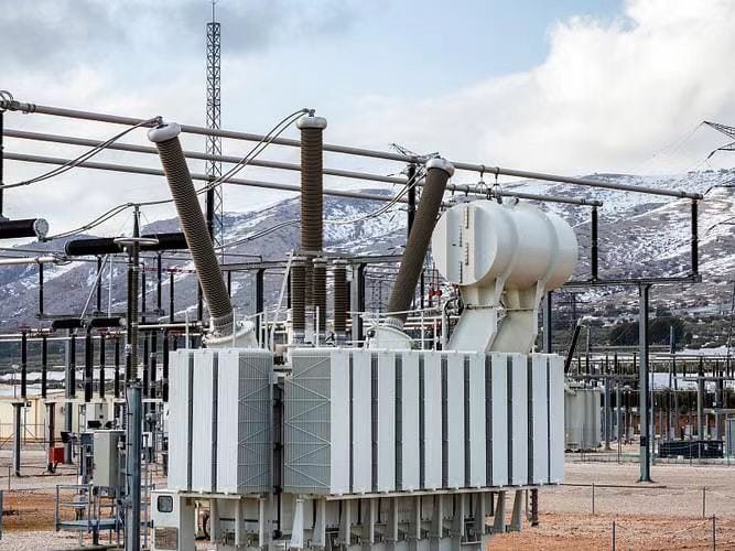
Why Are Power Transformers Critical in Transmission Networks?
Modern transmission networks are the lifelines of national energy systems—designed to deliver vast amounts of electricity across cities, regions, and even countries. But without one essential component, none of this would be possible: the power transformer. These transformers are not just pieces of equipment; they are the strategic gatekeepers that make high-voltage transmission viable, efficient, and safe. Without them, grid-scale energy movement would collapse under the weight of voltage loss, thermal overload, and system instability.
Power transformers are critical in transmission networks because they enable high-voltage, low-current transmission of electrical power over long distances, significantly reducing energy losses. By stepping up voltage at generation points and stepping it down near consumption zones, they improve grid efficiency, reduce conductor size, and ensure voltage stability. They also facilitate interconnection between different voltage levels and regions, providing flexibility, fault isolation, and load balancing.
In short, power transformers make the entire transmission system physically and economically possible.
Power transformers are essential for stepping up and stepping down voltage in transmission systems to enable efficient power flow.True
They reduce current levels, minimizing resistive losses, and make long-distance energy transfer practical and safe.
Transmission networks can operate efficiently without using power transformers.False
Without transformers, voltage cannot be adjusted for distance or load, leading to massive losses and system instability.
1. Voltage Transformation for Long-Distance Efficiency
| Process | Why It's Critical |
|---|---|
| Step-Up (Generator → Grid) | Increases voltage (e.g., 11 kV → 400 kV) to reduce current |
| Transmission Line Losses | Losses ∝ Current² × Resistance (I²R); reduced by higher voltage |
| Step-Down (Grid → Distribution) | Converts HV back to safe levels (e.g., 220 kV → 33 kV) |
Power transformers reduce line losses by up to 90% when operating at high voltages.
2. Grid-Level Load Balancing and Interconnection
| Function | How Power Transformers Help |
|---|---|
| Regional Grid Interconnection | Link areas with different voltage standards |
| Load Transfer Capability | Shift power between zones during peak demand |
| Voltage Regulation | Maintain voltage profile with on-load tap changers (OLTC) |
| Reactive Power Management | Control power factor and voltage support |
They serve as voltage gateways, connecting the puzzle pieces of the national grid.
3. Fault Isolation and Network Reliability
| Fault Scenario | Power Transformer Role |
|---|---|
| Grid Overload or Surge | Triggers differential protection or breaker trip |
| Internal Winding Fault | Detected by Buchholz relay or gas monitoring |
| Lightning/Surge Protection | Shielded via surge arresters and proper grounding |
| Short Circuit Handling | Designed to withstand thermal/mechanical forces |
Power transformers don’t just transfer power—they defend the grid.
4. System-Wide Economic Efficiency
| Without Transformers | With Power Transformers |
|---|---|
| Low-voltage transmission → high losses | High-voltage transmission → low I²R losses |
| Massive copper/aluminum conductors needed | Smaller conductor size due to reduced current |
| Voltage drop across long lines | Stable voltage maintained with regulation systems |
| Poor energy economics | Scalable, low-loss grid efficiency |
Using power transformers can save millions annually in transmission energy losses.
Voltage and Distance Matching Table
| Transmission Voltage | Typical Distance Range | Power Transformer Rating (MVA) |
|---|---|---|
| 132 kV | 50–150 km | 63–160 MVA |
| 220 kV | 100–300 km | 100–250 MVA |
| 400 kV | 200–600+ km | 315–500+ MVA |
| 765 kV (UHV) | 500–1000+ km | 630–1200+ MVA |
Higher voltage levels, made possible by power transformers, correlate directly with longer transmission reach.
Real-World Example
- Project: National HVDC Corridor, India
- Input Voltage: 400 kV AC
- Output Voltage: 220 kV AC
- Transformer Rating: 500 MVA, 3-phase
- Cooling Type: OFAF with 10 radiator banks
- Result: Reduced I²R losses by 70%, stable power delivery across 600 km
Enabled power balancing between regions with surplus and deficit generation.
Key Design Features for Transmission Use
| Design Feature | Transmission Benefit |
|---|---|
| High Voltage Insulation | Withstands grid surges and weather exposure |
| Heavy Windings & Bracing | Handles high current and fault mechanical stress |
| Tap Changer | Stabilizes output voltage under load changes |
| SCADA-Ready Monitoring | Real-time remote control and alarm triggering |
Conclusion
A power transformer is generally defined as a transformer rated above 200 kVA and used in high-voltage transmission systems, typically between 33 kV and 400 kV or higher. Its main purpose is to step up or step down voltage levels to enable efficient long-distance power flow. These transformers are built for maximum efficiency, durability, and thermal performance, operating mostly under full load. Understanding what qualifies as a power transformer helps in system design, procurement, and overall power infrastructure planning.
FAQ
Q1: What is considered a power transformer?
A1: A power transformer is a type of transformer specifically designed to transfer electrical energy at high voltage levels (typically above 33 kV) and large power capacities (usually above 500 kVA). It is primarily used in transmission networks and bulk power systems to efficiently step up or step down voltage for long-distance power delivery.
Q2: What voltage and capacity classify a transformer as a power transformer?
A2: Generally:
Voltage rating: Above 33 kV
Power capacity: Ranges from 500 kVA to several hundred MVA
These characteristics make power transformers suitable for interconnecting generation stations and transmission substations.
Q3: Where are power transformers used?
A3: Power transformers are used in:
Generating stations (step-up voltage for transmission)
Transmission substations (step-down voltage for distribution)
Inter-regional or cross-border power exchange networks
They form a critical link in high-voltage transmission infrastructure.
Q4: How does a power transformer differ from a distribution transformer?
A4: Key differences:
Power transformers handle high voltage, high load, and operate at constant load.
Distribution transformers operate at lower voltages, serve end users, and are designed for variable load conditions.
Power transformers are also physically larger and more complex.
Q5: What features are typical in a power transformer?
A5: Features include:
Tap changers for voltage regulation
Oil or forced-air cooling systems
High-grade insulation for high voltage handling
Monitoring equipment for temperature, pressure, and gas levels
These enable safe, efficient, and long-lasting operation in critical grid infrastructure.
References
"What Is a Power Transformer?" – https://www.transformertech.com/what-is-a-power-transformer
"Classification of Transformers by Voltage and Application" – https://www.electrical4u.com/power-transformer-definition
"Understanding Power Transformers in the Grid" – https://www.powermag.com/what-makes-a-power-transformer
"Energy Central: Role of Power Transformers in Infrastructure" – https://www.energycentral.com/c/ee/what-is-power-transformer
"Smart Grid News: High Voltage Transformer Use" – https://www.smartgridnews.com/power-transformer-grid-role
"ResearchGate: Power Transformer Function and Design" – https://www.researchgate.net/power-transformer-design-guide
"ScienceDirect: High Voltage Power Transformers Explained" – https://www.sciencedirect.com/power-transformer-overview
"PowerGrid: Types of Transformers and Their Functions" – https://www.powergrid.com/power-transformer-classification