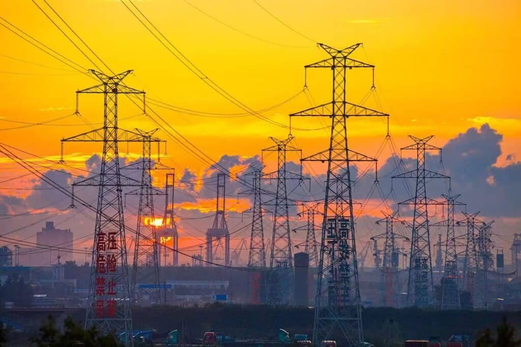
Transformers are vital components in the transmission and distribution of electrical energy. When a transformer "blows," it often leads to sudden power outages and safety concerns. Knowing how to recognize the signs of a blown transformer is essential for fast response, ensuring both public safety and system reliability.
What Does It Mean When a Transformer Is Blown?
When someone says a transformer has "blown," it's not just a power outage—it often signals a serious electrical failure that can involve intense heat, internal arcing, fire, or even small explosions. These events can damage infrastructure, interrupt supply to thousands of users, and create safety hazards. Understanding what “blown” really means in technical terms is essential for proper emergency response, asset management, and grid reliability.
A transformer is considered “blown” when it experiences a sudden, often catastrophic failure—usually caused by an internal fault like insulation breakdown, arcing, short-circuiting, or overheating. This leads to rapid energy discharge, oil ignition, and physical damage, resulting in loss of voltage regulation and automatic disconnection from the grid. Signs include a loud bang, smoke or fire, oil leakage, and immediate power outage in the affected area.
Such a failure can have wide-reaching effects on safety, service continuity, and environmental protection.
A blown transformer results from internal faults such as insulation failure, arcing, or thermal overload.True
These faults lead to energy discharge and irreversible damage, causing the transformer to trip offline and stop operating.
A transformer blowing is a minor issue that doesn’t interrupt power supply.False
Transformer blowouts usually cause immediate outages and significant damage that requires repair or full replacement.
1. What Happens Inside a Blown Transformer?
| Event | Description |
|---|---|
| Internal Arcing | Fault current jumps between windings or to core/frame |
| Insulation Breakdown | Overvoltage or heat causes dielectric failure |
| Oil Ignition or Vaporization | Heat turns oil into gas, increasing pressure and fire risk |
| Short Circuit | Winding contact or external fault causes a sudden power surge |
| Pressure Surge | Gases and heat rapidly expand, possibly rupturing the tank |
These internal faults destroy the transformer’s ability to regulate voltage or carry current, triggering automatic isolation.
2. Visual and Audible Signs of a Blown Transformer
| Indicator | Meaning |
|---|---|
| Loud bang or explosion | Instant arc fault or tank rupture |
| Smoke or flames | Oil ignition or burning insulation |
| Oil leak or spray | Pressure-relief valve triggered or tank cracked |
| Soot and burn marks | Fire around bushing or radiator |
| Power outage | Circuit breaker tripped; transformer offline |
These signs often appear within seconds of the failure, prompting emergency protocols.
3. Common Causes of Transformer Blowouts
| Cause | Mechanism |
|---|---|
| Lightning strike | Overvoltage leads to bushing flashover or winding arc |
| Overloading | Prolonged current flow overheats insulation and oil |
| Oil contamination | Moisture or particles reduce dielectric strength |
| Aging insulation | Degraded cellulose paper and varnish break down under stress |
| Internal mechanical failure | Vibration or loose connections result in arc initiation |
Regular testing and maintenance can identify these issues before they cause irreversible failure.
4. What Happens After the Transformer Blows?
| Consequence | Outcome |
|---|---|
| Transformer trip | Automatically isolated by protective relays (87T, Buchholz) |
| Grid segment outage | Power interruption for customers downstream |
| Emergency crew dispatch | On-site inspection and isolation |
| Root cause investigation | Required for insurance, repair, and prevention planning |
| Repair or replacement | Depending on fault severity and asset age |
Large power transformers may take days or weeks to replace, while smaller units can be swapped in hours.
5. Preventing Blowouts Through Early Intervention
| Preventive Action | What It Detects or Prevents |
|---|---|
| Dissolved Gas Analysis (DGA) | Arcing, overheating, early fault gases |
| Infrared Thermography | Hotspots in bushings or windings |
| Moisture monitoring | Prevents dielectric breakdown due to water ingress |
| Bushing inspection | Prevents flashover due to cracks or contamination |
| Overload monitoring | Avoids thermal overstress and winding degradation |
Transformers almost never fail without warning—most blowouts are preceded by detectable anomalies.
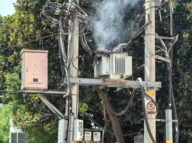
What Are the Common Visual and Audible Signs of a Blown Transformer?
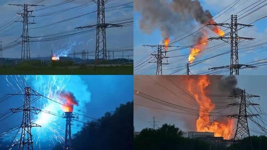
Transformers operate quietly and reliably—until they don’t. When a transformer blows, it’s not a silent failure. Whether it's a neighborhood pole-mounted unit or a high-voltage substation transformer, these events usually come with intense audible and visual signs that signal a serious malfunction. These cues are not just warnings—they indicate dangerous internal damage such as arcing, pressure surges, or insulation failure. Recognizing these signs quickly helps initiate emergency shutdown, public safety measures, and professional response.
The most common visual signs of a blown transformer include thick smoke, bright flashes or sparks, visible flames, charring around bushings or vents, and oil leakage or spray. Audible signs often include a loud explosive bang, hissing from escaping gas or oil, crackling of electrical discharge, and high-pitched whines. These indicators point to serious internal faults like short circuits, arc flash, or insulation failure and typically lead to immediate power outages and equipment shutdown.
These signs are unmistakable and require urgent action to ensure safety and prevent further grid disruption.
Blown transformers often produce loud noises and visible smoke, sparks, or flames.True
These symptoms result from high-energy arcing, overheating, or oil combustion during transformer failure.
Transformer blowouts are silent and invisible events that don’t show external signs.False
Most transformer failures are accompanied by loud sounds and visible damage, making them easy to detect.
1. Audible Signs of a Blown Transformer
| Sound | Description | Technical Cause |
|---|---|---|
| Loud bang or explosion | Sudden detonation-like sound, often heard over a wide area | Internal arcing, tank rupture, flashover |
| Crackling or popping | Rapid snapping sounds like electrical discharge | Corona effect or dielectric breakdown |
| Hissing or gurgling | Continuous escape of gas or boiling oil | Pressure buildup and release via PRD |
| High-pitched whining | Electrical hum escalating into piercing noise | Saturated core, partial discharge buildup |
These sounds signal severe internal stress and indicate that electrical protection systems have been triggered.
2. Visual Signs of a Blown Transformer
| Visual Cue | Interpretation | Root Cause |
|---|---|---|
| Bright flash or arc | Instantaneous flash seen near bushings or wires | High-voltage arc fault or bushing flashover |
| Plume of smoke | White, gray, or black smoke rising from the tank | Oil ignition, winding fire, or insulation burn |
| Flames or fire | Visible combustion near bushings, vents, or radiator | Oil fire triggered by internal arc |
| Oil spray or leakage | Stains or splashing from seams or conservator | Tank breach or pressure relief activation |
| Deformed or bulging tank | Visibly swollen transformer housing | Internal pressure from gas generation |
| Soot marks or charring | Blackened surfaces, often near fault initiation points | Burn damage from overheating or explosion |
These visual signs often last from several seconds to minutes, alerting utility workers and the public.
3. Signs Seen in the Surrounding Environment
| Effect | What It Suggests |
|---|---|
| Sudden blackout | Transformer disconnected from circuit due to fault |
| Flickering lights | Brief voltage dip before disconnection |
| Burnt smell or ozone | Presence of combustion byproducts or arcing |
| Alarm from nearby substation | Indicates automatic relay trip or PRD actuation |
In populated areas, multiple reports from the public often help pinpoint the exact location of the event.
4. Real-Life Example: Blown Pole-Mounted Transformer
- Location: Urban residential street
- Time: 7:45 PM, during high-load period
- Audible Sign: Loud "pop" followed by a crackling sound
- Visual Sign: Flash at the top of the pole, followed by a column of smoke
- Response: Fire department and utility dispatched within 10 minutes
- Root Cause: Moisture ingress in bushing + overloaded phase
- Outcome: Unit isolated, replaced within 6 hours, no injuries
The quick identification of visual and audible symptoms enabled safe and fast containment of the situation.
Summary Table: Signs of a Blown Transformer
| Type | Symptom | Meaning |
|---|---|---|
| Audible | Loud bang | Arc flash, tank rupture |
| Crackling or popping | Corona discharge, dielectric failure | |
| Hissing or gurgling | Oil/gas pressure release | |
| Whining electrical noise | Core saturation or internal discharge | |
| Visual | Flash or spark | Instantaneous fault, bushing breakdown |
| Smoke or soot | Burning oil or insulation | |
| Fire | Oil or insulation ignition | |
| Oil spray or leakage | Pressure buildup, ruptured seal | |
| Tank bulging | Gas accumulation and explosion risk |
How Does a Blown Transformer Affect Electrical Supply?
When a transformer blows, it doesn't just damage a piece of equipment—it disrupts the delicate balance of electrical supply across entire neighborhoods, cities, or even regional grids. Transformers are the voltage-regulating gateways of power systems, and when one fails, the flow of electricity is instantly interrupted, potentially triggering blackouts, brownouts, or cascading power instability.
A blown transformer affects electrical supply by immediately disconnecting power from the portion of the grid it serves, leading to blackouts, voltage drops, or equipment shutdowns in homes, businesses, or substations. Depending on the transformer's role—whether it’s at the generation step-up stage, in a high-voltage transmission system, or on the final distribution line—its failure can halt power flow to thousands of users, compromise grid stability, and force utilities to reroute or shed load to prevent further disruption.
These impacts occur within seconds, making automatic protection systems and rapid response critical.
A blown transformer causes immediate power loss in its service area and can disrupt grid balance.True
Transformers regulate voltage and connect segments of the power grid, so their failure leads to blackout or unstable voltage.
Transformer blowouts rarely affect electrical supply because the grid automatically reroutes power.False
While some rerouting is possible, a blown transformer typically causes service loss in the directly connected area.
1. What Happens to Power Flow When a Transformer Blows?
| Grid Function Lost | Resulting Supply Impact |
|---|---|
| Voltage transformation halted | Incompatible voltage prevents power transfer |
| Load disconnection | Power consumers lose supply instantly |
| Network segment isolation | Faulted zone removed to protect rest of grid |
| Load imbalance | Neighboring transformers may be overloaded |
| Reactive power loss | Grid voltage stability affected in adjacent zones |
In larger grids, protection systems may trip adjacent feeders or substations to prevent damage, expanding the affected area.
2. Type of Transformer Failure vs. Supply Disruption
| Transformer Type | Typical Impact on Electrical Supply |
|---|---|
| Pole-mounted (11 kV/400 V) | Power loss to homes, small businesses, 50–300 users |
| Distribution Substation (33 kV/11 kV) | Neighborhood-wide blackout, up to 10,000+ customers |
| Transmission Transformer (220–400 kV) | City or regional outage, grid frequency fluctuation |
| Generation Step-Up Unit | Generator disconnected from grid, loss of generation capacity |
A failure at higher voltage levels has exponentially broader impacts due to upstream dependencies.
3. Immediate Electrical Effects of a Blown Transformer
| Event | Effect on Supply System |
|---|---|
| Circuit Breaker Trip | Instant power interruption to downstream users |
| Voltage Collapse | Nearby equipment operates below threshold |
| Frequency Instability | Caused by mismatch between generation and load |
| Power Quality Degradation | Voltage sags, harmonics, and transient spikes |
| Loss of Redundancy | Increases risk of secondary outage |
Unplanned outages can last minutes to days, depending on transformer availability and fault location.
4. Real-World Example: Substation Transformer Blowout
- Location: 132/33 kV substation
- Load: 35 MVA supporting 20,000+ customers
- Incident: Transformer blew due to OLTC arcing
- Response Time: 0.3 seconds for relay trip, 3 hours to isolate and test
- Supply Impact: 4 hours blackout in industrial zone, delayed grid recovery
- Grid Stability Risk: Feeder rebalancing needed to avoid transformer overloading in nearby zones
A single failure at this level affected critical infrastructure, traffic systems, and internet service in the region.
5. Cascading Risk and Load Shedding After a Blown Transformer
| Secondary Effect | Why It Happens |
|---|---|
| Overload on nearby units | Remaining transformers pick up excess load |
| Load shedding implemented | To prevent overheating of neighboring transformers |
| Frequency drop | Loss of generation or supply shifts system balance |
| Voltage sag in feeders | Inadequate regulation when transformer is offline |
SCADA systems and protection relays automatically trigger load redistribution or disconnection to preserve system integrity.
6. How Utilities Restore Power After a Transformer Failure
| Step | Goal |
|---|---|
| Fault Isolation | Protect unaffected areas |
| Load Transfer or Backfeed | Use alternate feeders to restore supply |
| Mobile Substation Deployment | Temporary voltage support until new transformer arrives |
| Spare Transformer Installation | Replace failed unit for full recovery |
| System Re-synchronization | Restore voltage and frequency balance |
Some utilities maintain strategic spare transformers and mobile units to shorten downtime.
Summary Table: Blown Transformer Impact on Electrical Supply
| Impact Type | Description | Duration |
|---|---|---|
| Power Outage | Sudden loss of power to downstream users | Minutes to hours/days |
| Voltage Instability | Fluctuations in supply voltage | Seconds to system-wide |
| Feeder Overloading | Neighboring units stressed | Short-term, risk of further failure |
| Grid Segmentation | Faulted zone disconnected | Until replacement installed |
| Loss of Redundancy | Reduced capacity to absorb future faults | Ongoing until unit is replaced |
What Testing Methods Are Used to Confirm a Transformer Has Failed?
When a transformer shows signs of malfunction—like overheating, tripping, or a complete shutdown—it’s not enough to guess the cause. To confirm a transformer has truly failed, and determine whether it can be repaired or must be replaced, engineers must carry out a series of standardized electrical, thermal, mechanical, and chemical tests. These methods not only validate the failure but also help pinpoint the underlying cause, whether it’s internal arcing, insulation collapse, or winding damage.
Testing methods used to confirm a transformer has failed include insulation resistance tests, winding resistance measurement, dissolved gas analysis (DGA), transformer turns ratio (TTR) test, power factor (tan delta) test, sweep frequency response analysis (SFRA), and visual/mechanical inspection. These diagnostic tools assess the condition of insulation, windings, oil, and the transformer core to determine whether failure is total, partial, or recoverable.
These tests are essential for forensic evaluation, safety assurance, and insurance or warranty processing.
Transformers are tested using electrical, chemical, and mechanical diagnostics to confirm failure and assess repair viability.True
Tests like DGA, IR, TTR, and SFRA detect insulation damage, winding distortion, or internal arcing—key indicators of transformer failure.
Transformer failure can be confirmed just by looking at it or guessing from noise.False
Visual signs alone are not sufficient—technical testing is required to confirm and understand transformer failure.
1. Insulation Resistance (IR) Test
| Purpose | Detects | Tool Used |
|---|---|---|
| Measures insulation quality between windings and ground | Moisture ingress, insulation breakdown | Megger (500 V–5 kV) |
A sudden drop in resistance (below 100 MΩ for HV systems) is a red flag for insulation failure.
2. Winding Resistance Measurement
| Purpose | Detects | Tool Used |
|---|---|---|
| Measures DC resistance of transformer windings | Shorted turns, loose connections, or hot spots | Micro-ohmmeter |
Resistance imbalance between phases >2% indicates possible internal faults or deformed coils.
3. Dissolved Gas Analysis (DGA)
| Purpose | Detects | Tool Used |
|---|---|---|
| Analyzes gases dissolved in oil | Arcing, overheating, partial discharges | DGA test kit or lab analysis |
| Gas Type | Indicates |
|---|---|
| Hydrogen (H₂) | Partial discharges |
| Methane (CH₄) | Low-temperature overheating |
| Acetylene (C₂H₂) | High-energy arcing |
| Carbon Monoxide (CO) | Cellulose insulation degradation |
Abnormal gas levels or sudden increases point to internal failure progression.
4. Transformer Turns Ratio (TTR) Test
| Purpose | Detects | Tool Used |
|---|---|---|
| Compares actual voltage ratio to design spec | Winding deformation, open circuits | TTR meter |
A deviation of more than ±0.5% from rated turns ratio can indicate internal winding displacement.
5. Power Factor / Tan Delta Test
| Purpose | Detects | Tool Used |
|---|---|---|
| Measures dielectric loss of insulation | Aging, moisture, or contamination in solid/oil insulation | Tan delta test set |
High power factor (>1%) signals deteriorated dielectric strength, common in failed units.
6. Sweep Frequency Response Analysis (SFRA)
| Purpose | Detects | Tool Used |
|---|---|---|
| Analyzes frequency response of winding circuits | Mechanical deformation due to short circuits or transport damage | SFRA analyzer |
A "shift" in the curve indicates core or winding movement, often resulting from severe internal failure.
7. Visual and Mechanical Inspection
| Purpose | Detects | Common Findings |
|---|---|---|
| Manual inspection post-failure | Burn marks, oil leakage, mechanical deformation | Charred windings, cracked bushings, ruptured tank |
This is essential for validating test results and guiding repair/replacement decisions.
8. Additional Confirmatory Tests
| Test | Used For | Notes |
|---|---|---|
| Core Grounding Test | Checks insulation between core and tank | Confirms internal arc pathways |
| Magnetizing Current Test | Detects core damage | Abnormal draw = flux leakage or fracture |
| Oil Dielectric Breakdown Test | Tests insulating oil strength | Low breakdown voltage indicates aging |
| Leakage Current Test | Confirms HV to LV leakage paths | Especially useful for dry-type units |
Real-World Case: Failure Confirmation in a 220/66 kV Transformer
- Symptoms: High noise, rising oil temperature, Buchholz alarm
- Tests Performed: IR test failed, DGA showed high acetylene, SFRA confirmed winding displacement
- Diagnosis: Inter-winding short circuit + OLTC mechanical failure
- Result: Decommissioned, replaced with 100 MVA spare unit
- Learning: Oil monitoring and scheduled TTR testing would have flagged early warning
Summary Table: Key Tests to Confirm Transformer Failure
| Test Method | Failure Indicator | Confirmatory Role |
|---|---|---|
| Insulation Resistance (IR) | Low resistance to ground | Confirms insulation breakdown |
| DGA | Elevated gas levels (e.g., C₂H₂) | Confirms arcing or thermal failure |
| Winding Resistance | Phase imbalance or high resistance | Confirms shorted turns or coil damage |
| TTR | Ratio deviation | Detects winding deformation |
| SFRA | Frequency response shift | Detects mechanical damage inside core |
| Tan Delta | High dielectric loss | Identifies aged or failed insulation |
| Visual Inspection | Burn marks, oil stains, rupture | Verifies test results and safety hazard |
What Safety Precautions Should Be Taken Around a Suspected Faulty Transformer?
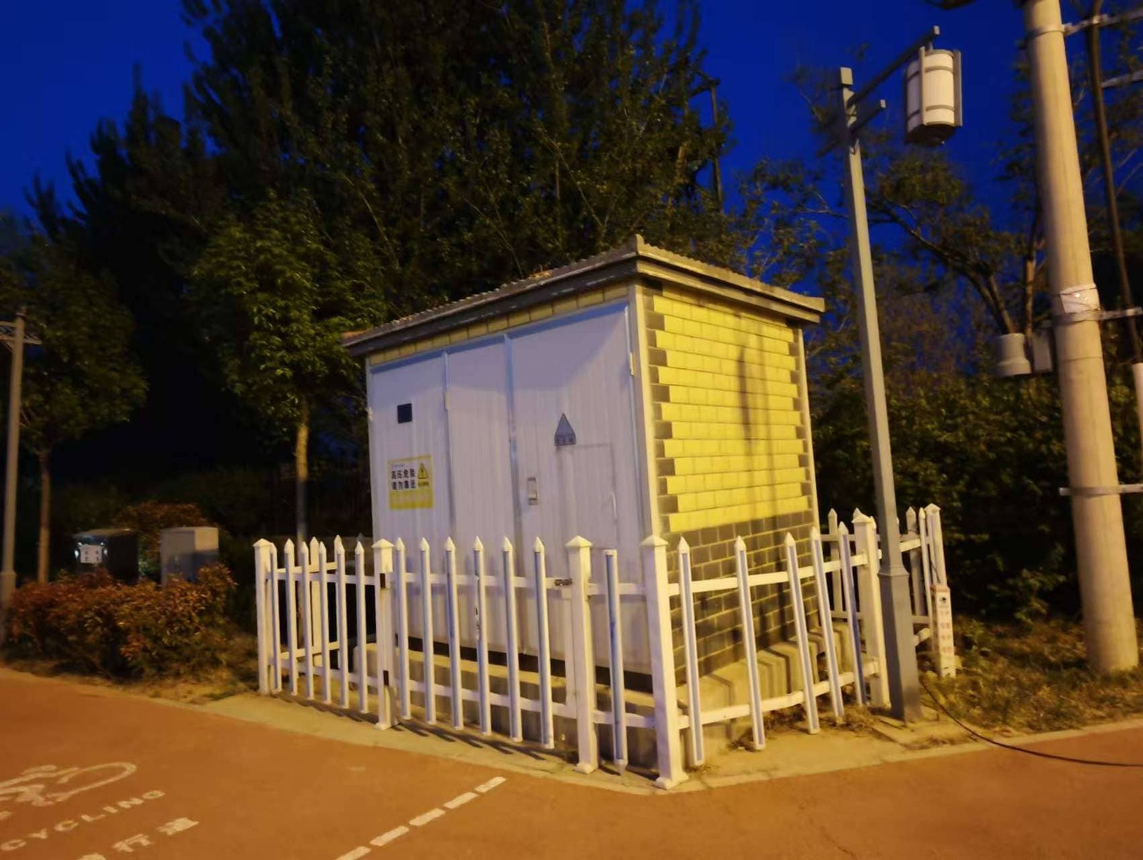
When a transformer is suspected of being faulty—whether due to noise, heat, oil leaks, smoke, or alarms—it becomes a potential electrical and fire hazard. Improper handling can lead to severe injury, electrocution, or catastrophic explosion. Before initiating any inspection or service, power companies and personnel must apply rigorous safety protocols to secure the area, protect personnel, and prevent escalation of the fault.
Safety precautions around a suspected faulty transformer include isolating the transformer from the electrical supply, establishing a secure safety perimeter with warning signs, wearing proper PPE (including arc-flash protection), grounding and discharging all circuits before inspection, avoiding contact with oil or leaked fluids, checking for flammable vapors, and using infrared or non-contact diagnostic tools before physical contact. All actions must follow lockout-tagout (LOTO) procedures and be supervised by qualified personnel.
These safety measures protect workers, infrastructure, and the public from high-voltage, thermal, and chemical hazards.
Personnel should wear arc-rated PPE, isolate power, and follow LOTO procedures when inspecting a suspected faulty transformer.True
Transformers under fault condition pose electrocution, fire, and explosion risks, which must be mitigated by standard electrical safety practices.
It's safe to approach and inspect a faulty transformer without special precautions if it's not visibly sparking.False
Even without external signs, faulty transformers may still hold dangerous voltages or internal pressure.
1. Initial Response and Area Control
| Step | Purpose |
|---|---|
| Secure the perimeter (10–30 m) | Prevent untrained personnel from entering the danger zone |
| Post warning signs and barriers | Alert public and staff of high-voltage hazard |
| Notify control center / SCADA | Coordinate system isolation and monitoring |
| Evacuate nearby buildings (if applicable) | Prevent risk from fire or explosion |
The area around a faulty transformer is considered a live hazard zone until confirmed safe by qualified engineers.
2. Electrical Isolation (LOTO Procedure)
| Action | Why It’s Critical |
|---|---|
| Open circuit breakers | Disconnects transformer electrically |
| Apply lockout-tagout devices | Prevents accidental re-energization |
| Verify de-energization | Confirm zero voltage on HV and LV terminals |
| Apply personal protective grounding | Discharges residual energy from windings |
Lockout-Tagout (LOTO) is legally required in most jurisdictions and saves lives in fault conditions.
3. Use of Personal Protective Equipment (PPE)
| Equipment | Protection Provided |
|---|---|
| Arc-rated flame-resistant (FR) suit | Protects from arc flash burns |
| Class 0 or Class 2 rubber gloves | Prevents electrocution from energized parts |
| Face shield and safety goggles | Defends against flying debris or oil splash |
| Hard hat and safety boots | Prevents injury from structural fall or fire |
| Respiratory protection (if smoke present) | Prevents inhalation of toxic gases |
PPE must meet NFPA 70E, OSHA 1910.269, or IEC 61482 standards depending on country and voltage class.
4. Non-Contact Fault Assessment First
| Tool | Purpose |
|---|---|
| Infrared (IR) camera | Detects overheating, potential hotspot faults |
| Ultrasonic leak detector | Identifies arcing or corona discharge |
| Gas sniffer or vapor analyzer | Detects explosive gas accumulation |
| Drone or pole camera | Visually inspect without entering risk area |
These tools allow safe assessment from a distance, preventing contact with live or unstable equipment.
5. Handling Oil or Leaks Safely
| Precaution | Reason |
|---|---|
| Do not touch or sample oil | May be at high temperature or under pressure |
| Contain spill using bunds or absorbents | Prevent soil or water contamination |
| Ventilate area if vapor buildup | Prevent flammable gas ignition |
| Use chemical-resistant gloves and aprons | If cleanup is necessary |
Older units may contain PCBs—a hazardous material requiring HAZMAT response protocols.
6. Wait Periods and Arc Flash Safety Zones
| Situation | Required Action |
|---|---|
| After audible arc or explosion | Wait 15–30 minutes before re-approaching (let gases vent) |
| When oil tank is bulging | Maintain a 10–20 meter standoff (risk of rupture) |
| Before inspection after tripping | Assume internal energy is still present |
Always treat the transformer as energized until proven otherwise by a qualified electrical test.
7. Only Authorized Personnel May Proceed
| Requirement | Why It Matters |
|---|---|
| Licensed high-voltage technician | Required for internal testing or opening terminals |
| SCADA coordination | Avoids re-energization during inspection |
| Permit-to-work (PTW) | Ensures all hazards are reviewed and mitigated |
Never allow untrained or unauthorized individuals to approach or tamper with suspected faulty transformers.
Summary Table: Key Safety Measures Around Faulty Transformers
| Category | Action | Purpose |
|---|---|---|
| Area Security | Fence, signs, evacuation | Prevent public access and hazard exposure |
| Isolation & Lockout | Breakers open, tags applied | Prevent accidental re-energization |
| PPE | Arc suit, gloves, helmet | Protect workers from arc, shock, debris |
| Assessment Tools | IR camera, gas detector | Diagnose faults from a safe distance |
| Environmental Safety | Spill control, vapor venting | Prevent fires and ecological harm |
How Can Regular Maintenance Help Prevent Transformer Failures?

Transformers are critical, high-value assets in every power system—yet they operate under constant electrical, thermal, and environmental stress. Over time, these conditions degrade internal insulation, oil quality, connections, and mechanical integrity. Without proper care, this deterioration can lead to catastrophic failures, expensive outages, and safety hazards. Fortunately, most transformer failures are not sudden—they are predictable and preventable through structured, regular maintenance.
Regular maintenance helps prevent transformer failures by identifying and correcting early signs of deterioration—such as insulation aging, oil contamination, thermal stress, and component wear—before they escalate into major faults. Key maintenance practices include dissolved gas analysis (DGA), oil filtration, thermal imaging, bushing inspection, on-load tap changer servicing, and electrical testing. These activities extend transformer life, reduce failure risk, and ensure safe, reliable operation.
When scheduled and executed effectively, maintenance transforms transformers from liabilities into long-life power assets.
Regular transformer maintenance can prevent failure by detecting early warning signs and resolving minor faults.True
Inspections and diagnostic tests reveal oil, insulation, and thermal issues before they cause catastrophic damage.
Maintenance has little impact on transformer performance or reliability.False
Neglecting maintenance leads to oil degradation, insulation failure, and component wear—major causes of transformer blowouts.
1. Preventive Maintenance Activities and Their Benefits
| Maintenance Task | Purpose | Failure Prevented |
|---|---|---|
| Dissolved Gas Analysis (DGA) | Detects internal arcing, overheating, insulation decay | Prevents winding and insulation failure |
| Oil Filtration and Testing | Removes moisture, acids, and sludge | Maintains dielectric strength |
| Infrared Thermography | Locates hotspots and loose connections | Prevents terminal or bushing burnout |
| On-Load Tap Changer (OLTC) Service | Cleans and replaces worn contacts | Prevents arc-induced OLTC failure |
| Bushing Inspection & Testing | Checks for cracks, leaks, or tracking | Prevents flashover and external arc faults |
| Insulation Resistance Testing | Verifies winding-to-ground integrity | Detects insulation weakening |
| Cooling System Maintenance | Ensures fans/pumps/radiators operate efficiently | Prevents thermal overload and oil aging |
These tasks form the foundation of Condition-Based Maintenance (CBM) and Life-Cycle Asset Management.
2. Early Warning Signs Identified Through Maintenance
| Sign Detected | Implication | Corrective Action |
|---|---|---|
| High acetylene in DGA | Active arcing inside windings | Immediate shutdown and inspection |
| Rising winding hotspot temp | Overload or cooling system failure | Load balancing or fan replacement |
| Moisture in oil | Leaky seals or degraded breathers | Oil reconditioning and gasket replacement |
| High tan delta value | Insulation loss due to aging or contamination | Oil filtration or insulation upgrade |
| Crack in porcelain bushing | Risk of external flashover | Replace bushing immediately |
Regular monitoring of these parameters enables intervention before irreversible damage occurs.
3. How Often Should Maintenance Be Performed?
| Task | Frequency (Standard Guidelines) |
|---|---|
| DGA Lab Test | Every 3–6 months (or continuous online) |
| Oil Quality and Moisture Test | Annually |
| Bushing Capacitance & Tan Delta | Annually |
| OLTC Inspection & Servicing | Every 2–4 years depending on operation count |
| IR Thermography | Quarterly to semi-annually |
| Winding Resistance and Ratio Test | Every 3–5 years or during overhaul |
Schedule may be tightened for aging transformers or those in high-load environments.
4. Real-World Example: Maintenance Preventing Failure
- Transformer: 220/132 kV, 160 MVA
- Issue Detected: Increasing CO and CO₂ in DGA samples over 3 months
- Response: Offline inspection revealed thermal stress on winding insulation
- Action Taken: Oil reconditioned, winding repositioned, OLTC serviced
- Result: No unplanned outage, extended life by 8–10 years
- Savings: Avoided \~\$1 million in replacement and downtime costs
This case shows how data-driven maintenance directly prevents catastrophic failures.
5. Benefits of Regular Transformer Maintenance
| Category | Benefit |
|---|---|
| Reliability | Reduces risk of sudden failure and blackout |
| Safety | Prevents arcing, fire, and explosion hazards |
| Cost Savings | Minimizes unplanned repairs, oil damage, and downtime |
| Asset Life Extension | Maintains equipment performance over 30–50 years |
| Regulatory Compliance | Meets utility and ISO safety inspection standards |
| Environmental Protection | Reduces oil spills and hazardous emissions |
Proactive maintenance is often more than 5× cheaper than emergency replacement after failure.
6. Maintenance and Monitoring Go Hand in Hand
| System Type | Role in Maintenance Program |
|---|---|
| Online DGA Monitors | Real-time fault gas tracking for early detection |
| SCADA and IED Systems | Load monitoring and thermal alert triggers |
| Transformer Health Index (THI) | Combines condition scores to prioritize actions |
| Digital Twin Modeling | Predicts future aging trends based on usage patterns |
These systems allow utilities to shift from calendar-based to condition-based maintenance, maximizing ROI.
Summary Table: How Regular Maintenance Prevents Transformer Failures
| Maintenance Action | Failure Mode Prevented | Resulting Benefit |
|---|---|---|
| Oil Testing & Filtration | Dielectric breakdown | Improved voltage insulation |
| DGA & Gas Monitoring | Internal arcing, overheating | Prevents irreversible core damage |
| OLTC Inspection | Arc wear, voltage instability | Stable tap performance |
| Bushing Testing | Flashover risk | Prevents external discharge events |
| Cooling System Servicing | Hotspot formation | Longer insulation life |
Conclusion
Identifying a blown transformer involves a combination of visible damage, strange noises, sudden power loss, and testing. Quick identification and action are crucial to reduce risks, avoid extended outages, and restore service. With advanced monitoring systems and regular maintenance, many transformer failures can be prevented before they cause major disruption.
FAQ
Q1: How can you tell if a transformer is blown?
A1: Common signs a transformer is blown include:
A loud explosion or pop
Visible smoke, flames, or sparking
A sudden power outage in the affected area
Burning smell or oil leakage (in oil-filled types)
Tripped breakers or fuse blowouts in the electrical panel
Q2: What does a blown transformer look or sound like?
A2: You may hear a loud bang, followed by arcing sounds or buzzing. Visually, a blown transformer may show:
Charred or blackened areas
Melted insulation or casing
Bulging or ruptured tanks
In severe cases, flames or smoke
Q3: Can a power outage alone confirm a blown transformer?
A3: Not always. A power outage may result from other issues like a tripped breaker, faulty wiring, or grid issues. However, if the outage is localized, involves noise or smoke, or follows a storm, a blown transformer is a likely cause.
Q4: How do technicians confirm a transformer is blown?
A4: Professionals use several diagnostic tools:
Dissolved Gas Analysis (DGA) for internal faults
Insulation resistance testing
Thermal imaging to detect hot spots
Turns ratio and winding resistance tests
These help verify whether the transformer needs repair or full replacement.
Q5: What should you do if you suspect a transformer is blown?
A5:
Stay away from the area for safety
Report it immediately to your utility provider
Do not touch any fallen lines or damaged equipment
Wait for certified personnel to inspect, de-energize, and repair the transformer
References
"How to Identify a Blown Transformer" – https://www.transformertech.com/blown-transformer-detection
"Signs of Transformer Failure and What to Do" – https://www.electrical4u.com/symptoms-of-blown-transformer
"Power Outages and Transformer Damage Explained" – https://www.powermag.com/transformer-failure-signs
"Diagnosing Transformer Faults with DGA and IR Testing" – https://www.sciencedirect.com/transformer-fault-testing
"Energy Central: How to Respond to Transformer Failures" – https://www.energycentral.com/c/ee/transformer-outage-response
"Smart Grid News: Preventing and Detecting Transformer Faults" – https://www.smartgridnews.com/detecting-transformer-failure
"ResearchGate: Transformer Fault Case Studies" – https://www.researchgate.net/transformer-damage-signs
"PowerGrid: What Happens When a Transformer Fails?" – https://www.powergrid.com/blown-transformer-symptoms