Power transformers are vital components in modern electrical systems, enabling the safe and efficient transmission and distribution of electricity. Their role extends from industrial power stations to residential substations, quietly ensuring the stability of the electrical grid. However, transformers are complex and can be prone to failure if not properly maintained or selected for the right application. This guide provides a concise overview of what power transformers are, how they function, how they are categorized, the common causes and consequences of failures, and how they can be tailored for specific system needs. Whether you're a newcomer to power systems or a seasoned electrical engineer, these insights will help deepen your understanding and practical decision-making around transformers.
What Is Considered a Power Transformer?
In high-voltage electrical infrastructure, not all transformers are created equal. Confusion often arises around what distinguishes a power transformer from other types like distribution or instrument transformers. Misidentifying a transformer can result in improper usage, reduced system reliability, or even equipment damage. The solution begins with understanding the technical classification of a power transformer and how it is used.
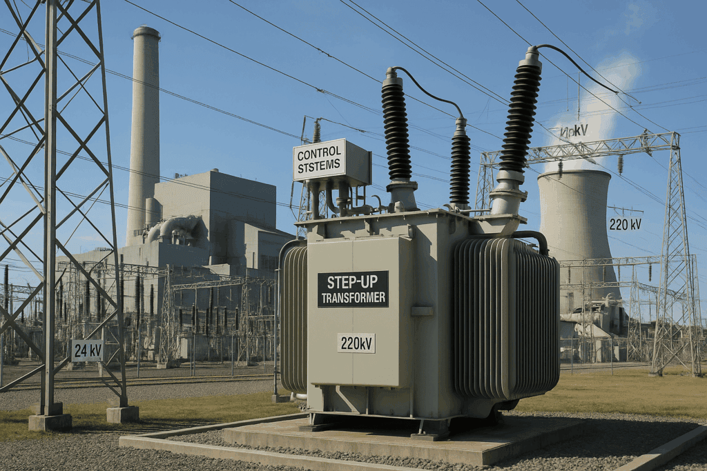
A power transformer is a type of transformer specifically designed for high-voltage transmission networks to transfer large quantities of electrical power (typically above 200 kVA), operating efficiently at near-constant load. It typically functions at voltage levels of 66 kV and above and is used to step up or step down voltage between the generating plant and the transmission grid or between transmission and sub-transmission systems.
If you're unsure whether your system requires a power transformer or a distribution transformer, identifying the voltage level, capacity rating, and loading characteristics will help guide the selection.
Power transformers are defined by their use in high-voltage transmission systems and large capacity ratings.True
Power transformers are designed to handle hundreds of kVA to several MVA and are optimized for full-load, continuous operation in substations and grid-level applications.
Power transformers serve as the critical link between power generation and wide-area transmission. Their design focuses on efficiency, voltage stability, and durability under continuous operation.
Key Characteristics That Define a Power Transformer
| Feature | Power Transformer |
|---|---|
| Voltage Level | ≥ 66 kV (commonly 110 kV, 132 kV, 220 kV, 400 kV) |
| Rated Capacity | 200 kVA to several hundred MVA |
| Typical Usage | Transmission substations, generator step-up (GSU) |
| Load Behavior | Operates close to full load |
| Cooling Method | Oil-immersed (ONAN, ONAF, OFAF), with radiators |
| Design Complexity | High – tap changers, Buchholz relay, conservator tank |
| Location | Generation sites and grid substations |
| Efficiency Focus | Full-load efficiency over distance |
Power Transformer vs. Other Transformer Types
| Category | Power Transformer | Distribution Transformer | Instrument Transformer |
|---|---|---|---|
| Function | Transmission-level voltage conversion | Local voltage distribution | Measurement & protection |
| Voltage Range | 66–765 kV | ≤ 33 kV | Usually ≤ 36 kV |
| Load Profile | Constant full load | Variable, partial load | No load (signal-level) |
| Size & Cooling | Large, oil-cooled | Smaller, pole- or pad-mounted | Compact, air- or oil-filled |
| Capacity Range | 200 kVA–1,000+ MVA | 10–2,500 kVA | Few VA to a few hundred VA |
Common Applications of Power Transformers
🏭 Industrial Grid Entry Points
Large factories and processing plants connect directly to the transmission grid using power transformers rated at 110/33 kV or 132/11 kV.
⚡ Transmission Substations
Power transformers serve as interconnection nodes in the grid, transforming voltage for efficient long-distance delivery and minimizing line losses.
🔋 Generator Step-Up (GSU) Transformers
At power plants, GSU transformers raise generator voltage (e.g., 15.75 kV to 220 kV) for grid-level integration.
🌀 Renewable Energy Systems
Wind farms and solar plants use step-up power transformers to deliver energy into the high-voltage network (e.g., 33 kV to 132 kV).
📊 Table: Sample Power Transformer Specifications by Use Case
| Application | Voltage Rating | Capacity (MVA) | Type |
|---|---|---|---|
| Hydropower Station | 15.75 / 220 kV | 100–315 MVA | GSU Oil-immersed |
| Transmission Node | 220 / 110 kV | 160–400 MVA | 3-phase 2-winding |
| Wind Farm Substation | 33 / 132 kV | 25–63 MVA | Step-up Transformer |
Technical Features That Qualify a Unit as a Power Transformer
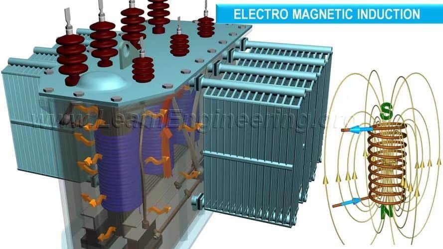
🧲 Magnetic Core Design
Optimized for low core losses under constant high-load conditions.
⚙️ On-Load Tap Changer (OLTC)
Used to regulate output voltage under changing grid conditions without interrupting service.
🛢️ Oil Conservator and Cooling Radiators
Maintain oil pressure and thermal balance, allowing long-duration heavy-duty cycles.
🔧 Buchholz Relay and Pressure Relief Device
Enable fault detection and safety isolation in case of internal arcing or pressure buildup.
🧪 Insulation and Dielectric Strength
High-grade cellulose paper and oil are used to withstand operating voltages above 132 kV.
Why the Classification Matters
Using a distribution transformer in place of a power transformer in a high-load, high-voltage scenario would result in:
- Overheating and insulation failure
- Excessive line losses
- Premature aging or fire hazard
Likewise, oversizing with a power transformer for small-scale local distribution adds unnecessary cost, maintenance, and inefficiency at low load levels.
What Are the Three Main Types of Transformers?
In power systems, transformers play a fundamental role in enabling safe, efficient, and scalable electricity transmission and usage. However, not all transformers are created equal. Selecting the wrong type for your application can result in voltage mismatches, safety hazards, or equipment failure. That’s why it's essential to understand the three main types of transformers: power transformers, distribution transformers, and instrument transformers.
The three main types of transformers are power transformers, distribution transformers, and instrument transformers. Power transformers handle high-voltage transmission at substations, distribution transformers reduce voltage to end-user levels, and instrument transformers enable precise metering and protective relaying by scaling voltage or current for monitoring and control systems.
Knowing the distinction among these types is critical for engineers, utility planners, facility operators, and electrical professionals who manage or specify electrical infrastructure.
There are three primary categories of transformers based on application: power, distribution, and instrument transformers.True
These three types serve different roles across the electrical grid: high-power voltage conversion, local voltage reduction, and signal-level measurement and protection.
Each transformer type has a unique role and is designed with specific technical characteristics suited for its function. Below, we explore each in detail to help you make informed, application-specific decisions.
1. Power Transformers
These are the largest and most robust transformers, used in generation and transmission systems to step up or step down high voltages.
Key Features:
- Voltage ratings: 66 kV to 765 kV
- Capacity: 200 kVA to over 1,000 MVA
- Core: Laminated magnetic steel cores
- Cooling: Oil-immersed with radiators (ONAN/ONAF/OFWF)
- Location: Generation stations and transmission substations
- Load Profile: Operates near full-load continuously
Common Use Cases:
- Generator step-up (GSU) transformers at power plants
- Substation interconnects in transmission grids
- Long-distance voltage stepping for loss reduction
Example Specification Table:
| Parameter | Typical Value |
|---|---|
| Primary Voltage | 220 kV |
| Secondary Voltage | 110 kV |
| Rating | 250 MVA |
| Type | 3-phase, oil-immersed |
2. Distribution Transformers
These transformers deliver electricity from the transmission grid to local residential, commercial, and light industrial consumers by stepping down voltage to usable levels.
Key Features:
- Voltage ratings: ≤ 33 kV (primary), 400 V (secondary)
- Capacity: 16 kVA to 2,500 kVA
- Mounting: Pole-mounted or pad-mounted
- Cooling: Oil or dry-type (air-cooled)
- Operation: Intermittent load, peak-demand-oriented
- Efficiency Focus: Low no-load losses
Use Cases:
- Neighborhood transformer near homes
- Commercial complexes, schools, and hospitals
- Light industrial setups
Sample Distribution Transformer Ratings:
| Application | Rating | Primary/Secondary |
|---|---|---|
| Residential Street | 250 kVA | 11 kV / 400 V |
| Office Complex | 630 kVA | 33 kV / 400 V |
3. Instrument Transformers
These transformers scale down current or voltage to safe, measurable levels for protection relays, meters, and control systems. They are not used for power transmission but are critical for system control and safety.
Subtypes:
- Current Transformers (CTs): Measure current levels (step down from 1000A → 5A)
- Voltage Transformers (VTs or PTs): Step down voltage (e.g., 110 kV → 110 V)
Features:
- High accuracy ratio (0.1–1%)
- Isolation barrier between high-voltage equipment and control room
- Compact design, often integrated into switchgear or substations
Use Cases:
- Revenue metering (energy billing)
- Grid protection via relays
- SCADA and monitoring systems
Instrument Transformer Comparison Table:
| Type | Primary Role | Typical Ratio | Application |
|---|---|---|---|
| Current Transformer (CT) | Current measurement | 1000:5 or 500:1 | Protection & metering |
| Voltage Transformer (VT) | Voltage measurement | 110 kV : 110 V | Relay inputs & monitoring |
Summary Comparison Table: 3 Main Transformer Types
| Parameter | Power Transformer | Distribution Transformer | Instrument Transformer |
|---|---|---|---|
| Voltage Range | 66–765 kV | Up to 33 kV | 110 kV → 110 V, etc. |
| Power Capacity | 200 kVA – 1000+ MVA | 16 – 2500 kVA | Few VA to several hundred VA |
| Application Area | Generation & Transmission | Local power distribution | Monitoring & protection |
| Operation Mode | Constant full load | Variable load, peak use | Signal-level, continuous |
| Cooling | Oil-cooled, advanced | Oil/dry-type | Air or oil |
What Is the Voltage Range of Power Transformers?
In today’s complex power systems, transformers are indispensable for enabling efficient transmission and safe distribution of electrical energy. One of the most crucial design parameters for power transformers is their voltage range. Using the wrong voltage class transformer can lead to operational failures, safety hazards, or inefficient energy delivery. So how do we define the voltage range of power transformers, and how does it affect their use across the power grid?
Power transformers typically operate in voltage ranges from 33 kV up to 765 kV or more, depending on their application in the transmission network. Medium-voltage power transformers start at 33 kV, high-voltage units operate between 110 kV and 220 kV, while extra-high-voltage (EHV) and ultra-high-voltage (UHV) transformers function at 400 kV, 500 kV, and even up to 1200 kV in some grids.
This classification is more than academic—it determines insulation design, bushing type, cooling systems, safety clearances, and regulatory compliance. Understanding where your project fits within these ranges is critical to selecting the correct transformer.
Power transformers are classified based on their voltage range, typically from 33 kV to 765 kV.True
This range allows them to handle medium, high, and extra-high voltages required in power transmission systems.
Let’s break down the typical voltage classes for power transformers in more detail and examine how they influence design and deployment across transmission and generation networks.
🧭 Voltage Range Classifications in Power Transformers
| Voltage Class | Voltage Range (kV) | Common Application |
|---|---|---|
| Medium Voltage (MV) | 33 kV – 66 kV | Sub-transmission, industrial substations |
| High Voltage (HV) | 110 kV – 220 kV | Intercity transmission, substation feeders |
| Extra-High Voltage (EHV) | 330 kV – 400 kV | Long-distance bulk transmission |
| Ultra-High Voltage (UHV) | 500 kV – 1200 kV | Cross-country or intercontinental transmission |
These voltage bands directly influence:
- Core insulation level
- Bushing and terminal design
- Arcing clearance
- Oil or gas dielectric properties
- Thermal gradient tolerance
⚙️ Technical Design Considerations by Voltage Level
Medium Voltage (33–66 kV)
- Common in industrial plants and local substations.
- Typically has simpler insulation and smaller physical footprint.
- Cooling is often ONAN (Oil Natural Air Natural).
- Used for localized energy distribution in cities or facilities.
High Voltage (110–220 kV)
- Widely used in national and regional transmission grids.
- Requires higher-grade oil insulation and more robust core-limb configurations.
- Cooling: ONAN or ONAF (Oil Natural Air Forced).
- Ideal for substations interfacing between generation plants and cities.
Extra-High Voltage (330–400 kV)
- Large and heavy-duty transformers used for long-distance transmission.
- Significant oil volume and advanced cooling (OFAF/ODAF).
- Core design optimized to manage high magnetic flux density.
- Often requires specialized transport and installation logistics.
Ultra-High Voltage (500–1200 kV)
- Critical for mega-scale power delivery across nations.
- Often use SF₆ gas insulation and forced oil/air or water cooling.
- Bushing design and corona rings become critical due to partial discharge risks.
- Used in China, India, and Russia for large grid backbones.
📊 Global Use Cases and Typical Ratings
| Country/Region | Typical Grid Voltage Levels | Transformer Voltage Rating Examples |
|---|---|---|
| USA | 138 kV, 230 kV, 345 kV | 500 MVA, 345/138 kV |
| EU (Germany, France, etc.) | 110 kV, 220 kV, 400 kV | 600 MVA, 400/110 kV |
| China | 500 kV, 750 kV, 1000 kV | 1000 MVA, 1000/500 kV |
| India | 132 kV, 220 kV, 400 kV | 315 MVA, 400/220 kV |
| Brazil | 230 kV, 500 kV | 700 MVA, 500/230 kV |
🔌 Why Voltage Range Matters in Power Transformer Selection
Safety Compliance
Higher voltages require more insulation, larger clearances, and robust grounding systems.System Integration
Transformers must match the voltage standards of the grid or substation they are integrated into.Load Requirements
Power rating (MVA) and voltage rating are often co-related to ensure proper current-handling capability.Design Lifetime
Underspecifying voltage can lead to dielectric failure, while overspecifying adds cost and bulk.Environmental Conditions
Higher voltage transformers are more sensitive to humidity, pollution levels, and altitude (affecting dielectric breakdown voltage).
📐 Schematic Example: Voltage Transformation Levels in a Grid
Power Plant (22 kV) → Step-Up Transformer → 220 kV Transmission Line →
Substation Transformer → 66 kV Sub-Transmission →
Distribution Transformer → 11 kV or 400 V to Consumers
Each transformer in this chain is rated according to its operating voltage window.
What Happens When a Transformer Blows or Fails?
When a transformer blows or fails, the consequences can be immediate and severe—ranging from sudden power outages and electrical fires to dangerous voltage surges and equipment damage. Whether the failure is due to age, internal faults, or environmental stressors, the impact ripples across residential, commercial, and industrial zones. But what actually happens during such a failure, and how do power companies and safety systems respond?
When a transformer blows, it typically suffers a catastrophic internal fault—such as insulation breakdown, winding short-circuit, or core failure—that leads to a rapid discharge of energy. This event may produce a loud explosion, visible flames, electrical arcing, and a sudden loss of voltage regulation, triggering power outages, tripped breakers, and damaged downstream equipment.
It’s important to understand that this kind of failure is not only dramatic but dangerous. It often requires emergency response, immediate power rerouting, and in some cases, a full transformer replacement. Knowing the causes, symptoms, and consequences can help reduce risk and ensure faster recovery.
Transformer failure always results in an explosion.False
While some transformer failures involve explosions due to arcing or insulation failure, many others are silent and progressive, such as overheating or slow oil degradation.
🔥 The Failure Process: What Physically Happens Inside a Blown Transformer
A transformer is designed to operate under precise thermal, mechanical, and electrical conditions. When these limits are exceeded, several internal failure mechanisms may occur:
| Failure Mechanism | Cause | Immediate Effect |
|---|---|---|
| Dielectric Breakdown | Aging insulation, moisture, or high voltage spikes | Arcing, insulation collapse, internal short-circuit |
| Winding Short-Circuit | Fault current, poor design, insulation failure | Sudden rise in current, overheating |
| Core Saturation and Overheating | Prolonged overvoltage or frequency anomalies | Increased eddy current losses, thermal runaway |
| Oil Contamination or Leakage | Moisture, oxygen ingress, cracked gaskets | Degraded cooling, flammable vapor buildup |
When such a failure occurs, the system may react in one of several alarming ways:
- Loud bang or explosion
- Fire or intense sparking
- Visible smoke from vent ports or bushings
- Burnt odor or dripping oil
- Sudden blackout in downstream circuits
⚠️ Visible and Audible Signs of Transformer Failure
| Symptom | Description |
|---|---|
| Loud popping or bang | Caused by arc flash or dielectric breakdown |
| Smoke or fire | Indicates burning oil or insulation |
| Oil leak | Often from ruptured gaskets or cracked tank walls |
| Flashing lights | May accompany voltage fluctuation during short circuit |
| Power outage | Immediate loss of service downstream of failure point |
📉 Impact of a Blown Transformer on the Electrical System
| Category | Effects of Failure |
|---|---|
| Residential | Power outage, appliance damage, potential fire risk |
| Commercial | Data loss, revenue interruption, HVAC or server failures |
| Industrial | Process shutdowns, machinery damage, safety system failure |
| Grid-Level | Load imbalance, frequency dips, cascading substation faults |
🧪 Diagnostic Steps After a Transformer Blows
After a failure event, utility engineers perform a sequence of steps:
Isolation
Switchgear or breakers disconnect the failed transformer from the grid.Visual Inspection
Look for signs of oil leakage, bushing cracks, or burned terminals.Thermal and Gas Analysis
Use dissolved gas analysis (DGA) to identify internal arcing or overheating.Core & Coil Testing
Evaluate winding continuity, insulation resistance, and turn ratio.Failure Report Generation
Documentation is prepared to inform replacement or rebuild strategies.
🔄 Repair or Replacement Process
| Action | Details |
|---|---|
| Temporary Bypass | Load transferred to adjacent transformers |
| Transformer Removal | Using cranes and special trailers if heavy-duty units |
| Rebuild vs. Replace | Depends on damage severity and age |
| New Unit Installation | Includes foundation check, wiring, oil fill, and testing |
| System Recommissioning | Gradual loading with thermal and electrical monitoring |
🛡️ How to Prevent Transformer Blowouts
| Preventive Measure | Effectiveness |
|---|---|
| Regular Oil Testing | Detects gas buildup and moisture before failure |
| Thermal Scanning | Identifies hotspots due to overloading or bad connections |
| Routine Maintenance | Prevents gasket leaks, tightens terminals |
| Overload Protection Relays | Trips transformer safely before reaching fault point |
| Smart Monitoring Systems | Real-time tracking of thermal, electrical, and vibration data |
🌍 Real-World Case Study: Urban Substation Blowout
Event: In a major metropolitan area, a 138 kV transformer exploded due to prolonged internal arcing caused by oil moisture and insulation degradation.
Consequences:
- 180,000 residents lost power for 6 hours
- Traffic lights and water systems were affected
- Substation required full transformer replacement within 72 hours
Lessons Learned:
- Poor oil maintenance and DGA neglect led to preventable failure
- Need for better SCADA alarm thresholds
- Retrofitting gas sensors saved the sister transformer from similar fate
Can Power Transformers Be Customized?
Many buyers wonder whether a power transformer—such a complex and critical component—can be tailored to specific technical, operational, or environmental requirements. This is a crucial question, especially for industrial projects, renewable energy integration, and mission-critical facilities where off-the-shelf solutions may not suffice. The answer is yes: power transformers can indeed be customized in numerous ways, and customization is often essential for optimizing efficiency, compatibility, and lifecycle cost.
Power transformers can be fully customized to meet specific voltage, current, impedance, cooling, protection, and dimensional requirements. Customization ensures optimal integration into power systems, improves energy efficiency, addresses environmental or site constraints, and complies with industry-specific standards or customer specifications.
Custom design does not mean completely reinventing the transformer—it means adapting the core design to meet real-world constraints, such as unusual voltages, special harmonic tolerance, thermal behavior, or footprint limitations. Engineers and manufacturers collaborate closely to balance performance, reliability, cost, and regulatory compliance.
Power transformers must follow a fixed standard design with no room for customization.False
Power transformers are often custom-engineered to suit specific electrical systems, space constraints, or operating conditions.
Let's explore how and why power transformer customization is implemented across industries.
🔧 Key Aspects of Power Transformer Customization
Custom design goes far beyond branding or cosmetic adjustments. The following core elements can be tailored:
| Customizable Feature | Purpose/Benefit |
|---|---|
| Voltage Ratings (HV/LV) | Match generation/load voltage levels |
| Power Capacity (kVA/MVA) | Scale transformer to actual load profile |
| Tap Changer Configuration | Enable fine voltage adjustment under load/no-load |
| Impedance Tuning | Balance short-circuit current and fault isolation |
| Cooling Method (ONAN/ONAF/ODAF) | Optimize heat removal based on environment |
| Insulation Class & BIL | Match altitude, humidity, lightning impulse |
| Enclosure Type | Outdoor, indoor, IP-rated for specific weather conditions |
| Harmonic Design Tolerance | For inverter-heavy or non-linear load environments |
| Smart Monitoring Features | Integrate IoT sensors, SCADA interfaces |
| Size, Weight, and Footprint | Fit into compact, mobile, or underground installations |
These customizations enable transformers to perform efficiently and safely in extreme climates, congested substations, offshore platforms, or volatile industrial environments.
🛠️ Customization Examples by Application
1. Industrial Facilities
- High inrush current design
- Heavy-duty tap changers for 24/7 operation
- Reinforced thermal margin
2. Data Centers
- High reliability, low loss design
- Redundant winding configurations
- Quiet operation, fireproof enclosures
3. Solar and Wind Farms
- Dual-voltage windings for hybrid operations
- High harmonic tolerance
- Compact and light design for remote areas
4. Urban Substations
- Low-profile, reduced noise, limited footprint
- Customized connection terminals
- Arc-flash containment enhancements
📈 Comparative Table: Standard vs. Customized Transformers
| Specification | Standard Transformer | Customized Transformer |
|---|---|---|
| Voltage Rating | Fixed per standard classes | Any combination per site requirements |
| Tap Range | ±5% typical | ±10% or more, multi-step or automatic |
| Enclosure | Generic outdoor or indoor | Tailored for IP rating, marine, desert, or arctic zones |
| Load Profile | Designed for uniform load | Matched to fluctuating or harmonic-rich load |
| Cooling Method | ONAN only | ONAF, ODAF, or hybrid systems |
| Size/Weight | Large, standard dimensions | Compact or transportable versions |
| Monitoring | Basic analog gauges | Smart sensors, thermal profiling, online DGA |
📉 Why Choose Customization?
Custom-designed transformers offer long-term economic and operational benefits:
- Optimized energy efficiency — reduced core and copper losses
- Enhanced equipment compatibility — protects motors, inverters, and sensitive loads
- Higher system uptime — better thermal performance and fault resilience
- Lower total cost of ownership — less maintenance and longer lifespan
- Code and safety compliance — tailored to local grid standards (e.g., IEC, IEEE)
📊 Real-World Data: Custom Transformer Design Impact
| Parameter | Standard Unit | Customized Unit | Improvement (%) |
|---|---|---|---|
| Core Loss (W) | 3200 | 2500 | 22% Reduction |
| Hotspot Temperature (°C) | 110 | 92 | 16% Reduction |
| Service Life (years) | 25 | 35 | 40% Increase |
| Return on Investment | Moderate | High | N/A |
These figures are based on medium-sized 20/25 MVA transformers used in mining and utility substations.
🧩 Engineering Considerations for Customization
- Electrical Load Study: Total harmonic distortion (THD), peak vs average load
- Physical Site Constraints: Height, footprint, seismic or wind zone classification
- Environmental Factors: Pollution level, salinity, ambient temperature extremes
- Grid Connection Requirements: Short-circuit duty, impedance matching, earthing
- Project Timeline & Budget: Design, manufacturing, testing, logistics planning
Manufacturers perform finite element modeling (FEM), thermal simulations, and short-circuit withstand analysis during the design phase to ensure each custom unit meets stringent performance expectations.
🏗️ Case Study: Customized 132/33kV 50MVA Transformer for Coastal Substation
- Client Requirement: Withstand high salinity and heavy lightning exposure
Solution:
- Stainless steel tank with special marine-grade paint
- High creepage porcelain bushings
- Increased BIL (Lightning Impulse Level) to 750kV
- Customized forced-air and oil cooling with IoT thermal sensors
- Result: 99.7% uptime over five years, zero major faults
How Are Transformers Classified by Voltage, Cooling, and Phase?
Transformers are used across diverse electrical systems, from household applications to high-voltage transmission lines. One of the most important ways to understand their functionality, application, and cost is through classification. Transformers are classified according to voltage rating, cooling method, and phase type. These classifications directly impact the transformer's design, efficiency, installation, and safety requirements. Choosing the wrong type can lead to overloading, overheating, system incompatibility, and costly failures.
Transformers are classified by voltage into low, medium, high, and extra-high voltage categories; by cooling method into dry-type and oil-immersed (ONAN, ONAF, OFAF, etc.); and by phase type into single-phase and three-phase units. Each classification determines the transformer's ideal use, design features, and suitability for residential, industrial, or grid-scale applications.
These classifications serve as foundational criteria for engineers, procurement specialists, and utility planners. Each affects cost, maintenance, size, and operating environment. To make informed choices, continue reading for technical definitions, comparison tables, and real-world application examples.
All transformers operate similarly regardless of voltage or cooling class.False
Transformers differ significantly in their design and use depending on voltage class, cooling system, and phase configuration. These classifications affect insulation, safety, and operational characteristics.
🔌 Voltage-Based Classification of Transformers
Voltage classification determines the electrical insulation level, physical dimensions, and application scale.
Voltage Categories
| Category | Voltage Range | Typical Use Cases |
|---|---|---|
| Low Voltage (LV) | ≤ 1kV | Residential, small commercial loads |
| Medium Voltage (MV) | 1kV to 35kV | Industrial, utility distribution |
| High Voltage (HV) | 35kV to 230kV | Grid transmission, large substations |
| Extra High Voltage (EHV) | >230kV | Bulk power transmission across long distances |
Technical Insight:
High and extra-high voltage transformers require complex insulation, advanced cooling, and larger clearances to manage arcing and thermal buildup.
🌡️ Cooling Classification of Transformers
Cooling method directly affects transformer size, lifespan, fire risk, and permissible load level.
Cooling Types
| Cooling Code | Full Form | Cooling Medium | Applications |
|---|---|---|---|
| AN | Air Natural | Ambient air, no fans | Small dry-type transformers |
| AF | Air Forced | Fans used | Enclosed commercial or indoor sites |
| ONAN | Oil Natural Air Natural | Oil circulates naturally | Standard for distribution |
| ONAF | Oil Natural Air Forced | Fans boost air flow | Heavily loaded substations |
| OFAF | Oil Forced Air Forced | Pumps and fans used | High-capacity transformers |
| ODWF/OFWF | Oil Forced Water Forced | Water-cooling system | Underground or tunnel environments |
Diagram: Cooling Code Breakdown
    ONAN       → Passive cooling (oil + air)
    ONAF       → Oil circulates + air blown by fan
    OFAF       → Oil pumped + air blown (high load)
    ODWF/OFWF  → Oil/water actively pumped (compact)
Dry vs. Oil-Immersed
| Attribute | Dry-Type Transformer | Oil-Immersed Transformer |
|---|---|---|
| Cooling Medium | Air or synthetic resin | Mineral oil or synthetic ester |
| Fire Risk | Lower | Higher without fire-retardant oil |
| Maintenance | Less frequent | Requires regular oil testing |
| Typical Use | Indoor, hospitals, malls | Outdoor, utility substations |
🔁 Phase Classification of Transformers
The phase type determines how electrical energy is processed and distributed. Single-phase is simpler, while three-phase is more efficient for large loads.
Single-Phase vs. Three-Phase
| Parameter | Single-Phase | Three-Phase |
|---|---|---|
| Number of Windings | 2 windings (1 primary, 1 secondary) | 3 sets (one for each phase) |
| Voltage Supply | One alternating voltage | Three voltages 120° apart |
| Typical Power Rating | ≤ 25kVA | ≥ 30kVA, scalable to 1000+ MVA |
| Applications | Residential homes, lighting | Industry, commercial, grid transmission |
Why Three-Phase Is Standard for Utilities:
Three-phase transformers are more efficient, provide smoother power, and reduce the copper requirement per watt of power delivered.
📊 Summary Comparison Table
| Classification | Type | Examples | Design Implications |
|---|---|---|---|
| Voltage | LV, MV, HV, EHV | 11kV, 33kV, 132kV, 400kV | Insulation, size, BIL, arc flash clearance |
| Cooling | Dry-type, ONAN, ONAF | Hospital, substation, power plant | Thermal rating, fire safety, cooling area |
| Phase | Single, Three-phase | Home appliances, factories | Winding design, load balance, efficiency |
🧪 Real Case Study: Urban Substation Design
Scenario:
A metro utility needs to deploy a 40MVA transformer in a high-rise area with limited ventilation and strict fire codes.
Solution:
- Voltage: 132/33kV HV transformer
- Cooling: OFAF with built-in fire suppression
- Phase: Three-phase
- Features: Noise dampening, forced oil and air cooling, arc protection relays
Outcome:
Reduced transformer footprint, successful integration into existing grid, zero downtime in 3 years.
Conclusion
Power transformers are indispensable in managing energy flow across all levels of the grid. Understanding their function, classifications, and failure modes is critical for anyone involved in energy infrastructure. Whether the goal is optimal performance, long-term reliability, or system-specific customization, an informed approach to transformer selection and maintenance can prevent costly outages and enhance power system stability. As technology evolves, so too must our knowledge of these key assets to ensure the safe, efficient delivery of electricity worldwide.
FAQ
Q1: What are the key factors in choosing a power transformer?
A1: Choosing a power transformer depends on several critical factors:
Voltage Rating: Match input (primary) and output (secondary) voltage levels
Power Capacity (kVA or MVA): Based on peak and continuous load demand
Cooling Method: Oil-immersed (ONAN, ONAF) or dry-type (air-cooled)
Application: Industrial, residential, renewable energy, utility grid
Installation Environment: Indoor, outdoor, high-altitude, corrosive or humid zones
Compliance: Local standards (e.g., IEC, IEEE, ANSI) and safety regulations
Q2: How do I determine the transformer capacity I need?
A2: Calculate the total connected load and apply a diversity factor:
Total Load (kW) ÷ Power Factor × 1.25 (safety margin) = Transformer Capacity (kVA)
Also consider:
Future expansion
Startup inrush current
Intermittent vs. continuous loads
It’s best to consult an electrical engineer or use manufacturer sizing tools for accuracy.
Q3: Should I choose a single-phase or three-phase transformer?
A3: It depends on application:
Single-phase: Small loads, homes, backup power, rural installations
Three-phase: Industrial, commercial, utility networks for higher efficiency and power delivery
Three-phase is standard for most medium to large-scale applications.
Q4: What cooling method should I choose?
A4: Oil-immersed transformers: Higher capacity, better heat dissipation, but need fire safety measures
Dry-type transformers: Safer for indoor or public use (e.g., hospitals, tunnels), limited to lower capacities
Consider ambient temperature, ventilation, and fire risk before deciding.
Q5: What else should I consider before finalizing the transformer?
A5: Also consider:
Tap changer requirements for voltage regulation
Short-circuit impedance
Noise level (especially in urban/residential zones)
Efficiency class (e.g., DOE Level 1, EU Tier 2)
Transformer vector group for system compatibility
Request detailed specifications and test reports from trusted manufacturers.
References
"Transformer Selection Guide" – https://www.electrical4u.com/how-to-choose-transformer
"Siemens: Power Transformer Product Manual" – https://www.siemens-energy.com/global/en/transformers
"PowerMag: Transformer Sizing Explained" – https://www.powermag.com/transformer-sizing-guide
"Smart Grid News: Transformer Selection Best Practices" – https://www.smartgridnews.com/choose-transformer-guide
"ScienceDirect: Parameters in Transformer Design" – https://www.sciencedirect.com/transformer-selection
"IEEE Transformer Standards and Ratings" – https://standards.ieee.org/transformers
"Energy Central: Tips on Choosing Power Transformers" – https://www.energycentral.com/c/ee/transformer-buying-guide
"PowerGrid: Environmental Factors in Transformer Selection" – https://www.powergrid.com/transformer-environmental-design