In today’s electrical and energy systems, the need to understand fundamental devices like power transformers and inverters has become essential—especially for professionals working in energy, industrial automation, and electrical engineering. Although both are critical components in power conversion and transmission, their roles, operating principles, and applications differ significantly. This document explores those distinctions through six core questions that clarify their functions, designs, and integration into modern power systems.
What Is a Power Transformer and How Does It Work?
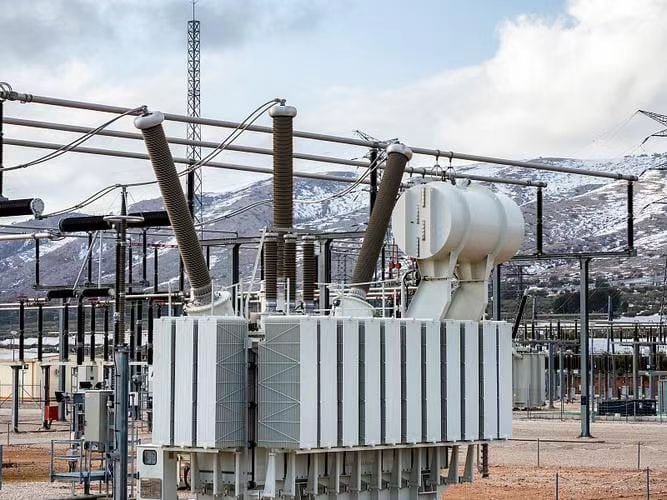
A power transformer is a vital component of electrical transmission systems, responsible for transferring electrical energy between circuits while modifying voltage levels. Without transformers, transmitting electricity over long distances would result in massive power losses, infrastructure overloads, and dangerously high or low voltages. Misunderstanding how transformers work could lead to inefficient power planning, equipment failure, and even hazardous installations. That’s why it's crucial to understand both what a power transformer is—and how it operates.
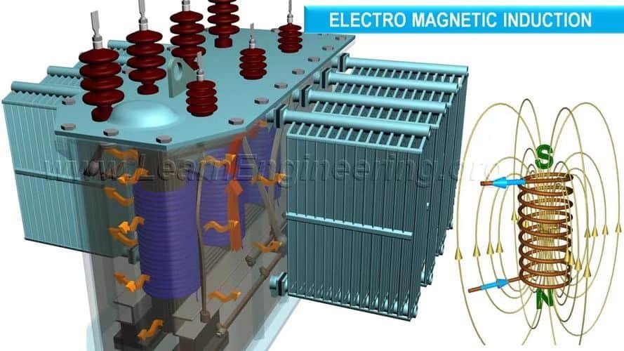
A power transformer is an electrical device that transfers alternating current (AC) power between two or more circuits through electromagnetic induction, primarily to step up (increase) or step down (decrease) voltage levels. It operates based on Faraday’s Law of Electromagnetic Induction: a changing magnetic field within its laminated core induces a current between primary and secondary windings, with the voltage ratio directly proportional to the winding turns ratio.
If you need to power a city from a distant power plant, step up voltage to minimize losses. If you need to safely power homes or equipment, step it down. The entire global power grid depends on this precise function. Keep reading to fully grasp how power transformers enable modern electricity transmission.
Power transformers are only used to lower voltage.False
Power transformers are used to either increase or decrease voltage levels depending on the application and grid location.
🔄 The Basic Working Principle of a Power Transformer
Electromagnetic Induction at Work
Power transformers work only with AC electricity. They operate based on mutual induction, where a changing current in the primary coil creates a magnetic field in the core, inducing a voltage in the secondary coil.
| Component | Function |
|---|---|
| Primary Winding | Receives input voltage; generates magnetic flux |
| Magnetic Core | Conducts magnetic flux; enhances efficiency |
| Secondary Winding | Receives induced voltage; delivers adjusted voltage to the load |
Formula That Governs Transformer Operation:
$$
\frac{V_1}{V_2} = \frac{N_1}{N_2}
\quad \text{and} \quad
\frac{I_1}{I_2} = \frac{N_2}{N_1}
$$
Where:
- $V_1, V_2$: Voltages of primary and secondary
- $N_1, N_2$: Number of turns in primary and secondary windings
- $I_1, I_2$: Currents in primary and secondary circuits
This means increasing voltage reduces current and vice versa—key to efficient long-distance power transmission.
📊 Key Components of a Power Transformer
| Component | Purpose |
|---|---|
| Core (CRGO steel) | Conducts magnetic flux between coils |
| Windings (Copper/Aluminum) | Carry input/output current; insulated to prevent arcing |
| Insulation Oil | Cools and insulates live parts |
| Conservator Tank | Maintains oil volume under thermal expansion |
| Buchholz Relay | Detects gas buildup and internal faults |
| Tap Changer | Adjusts output voltage under load or offload conditions |
Illustration: Core and Coil Layout
         Magnetic Core
      ___________________
     |                   |
     |   |||||||||||||   |  ← Primary winding (High Voltage)
     |   |||||||||||||   |
     |   =============   |  ← Core (Laminated Steel)
     |   |||||||||||||   |  ← Secondary winding (Low Voltage)
     |___________________|
🔌 Step-Up vs. Step-Down Operation
| Transformer Type | Primary Use | Example Voltage |
|---|---|---|
| Step-Up | From power plants to transmission lines | 11kV → 220kV |
| Step-Down | From substations to homes/industries | 66kV → 11kV or 400V |
Real-Life Grid Journey:
| Stage | Voltage Level | Transformer Role |
|---|---|---|
| Generation Plant | 11–33 kV | Step-up Transformer |
| Transmission Network | 110–500 kV | Voltage kept high for efficiency |
| Primary Substation | 220 kV → 66 kV | Step-down Transformer |
| Secondary Distribution | 11 kV → 400 V | Distribution Transformer |
🌡️ Transformer Cooling and Insulation
To maintain performance, transformers use various cooling techniques:
| Cooling Method | Used For | Medium |
|---|---|---|
| ONAN | Small/medium transformers | Oil + natural air |
| ONAF | Large, high-load conditions | Oil + forced air |
| Dry-type | Indoor or safety-sensitive use | Air-cooled |
Power transformers can run continuously without any cooling system.False
Continuous high-load operation without adequate cooling leads to insulation failure, overheating, and eventual transformer breakdown.
📈 Efficiency and Losses
Despite their size, modern power transformers boast efficiencies over 98%, thanks to:
- High-quality CRGO core (Cold Rolled Grain Oriented steel)
- Optimized winding geometry to minimize copper losses
- Controlled flux leakage paths
- Regular maintenance of insulation and oil
| Loss Type | Cause | Mitigation |
|---|---|---|
| Iron Loss (Core) | Hysteresis and eddy currents in core | Use laminated silicon steel cores |
| Copper Loss | Resistance in windings | Use high-purity copper, better cooling |
| Stray Losses | Magnetic leakage, eddy currents | Compact winding layout, shielding |
🏭 Applications of Power Transformers
| Sector | Function |
|---|---|
| Power Plants | Step-up voltage for efficient transmission |
| Substations | Step-down voltage for distribution |
| Industries | Provide regulated voltage for machinery |
| Data Centers | Ensure uninterrupted power delivery |
| Railways | Support traction substations |
| Renewable Energy | Integrate solar/wind generation into the main grid |
🔍 Real-World Example: 220/66 kV 100 MVA Transformer
| Specification | Details |
|---|---|
| Input Voltage | 220,000 Volts |
| Output Voltage | 66,000 Volts |
| Power Rating | 100 MVA |
| Cooling Type | ONAF |
| Impedance | 8.5% |
| Application | Inter-substation grid transmission |
| Tap Range | ±10% OLTC |
Transformers used in renewable energy grids are different in principle.False
Power transformers used in renewable grids operate on the same electromagnetic principle, though they may be optimized for lower fault levels or variable inputs.
What Is an Inverter and What Is Its Main Role?
In today’s electrified world, many modern systems—from solar panels to battery banks—generate or store DC (Direct Current) electricity, while nearly all household and industrial appliances require AC (Alternating Current) to function. Without a proper intermediary, these systems cannot operate together efficiently or safely. This is where inverters come in. Failing to understand how inverters work can lead to incompatible system design, damage to equipment, or inefficient energy use. If you're working with off-grid power, solar systems, or backup setups, knowing the role of an inverter is absolutely critical.
An inverter is an electronic device that converts direct current (DC) into alternating current (AC), enabling the use of DC power sources—such as solar panels or batteries—with standard AC-powered devices and the electrical grid. The inverter not only transforms voltage and current type but also regulates waveform quality, frequency, and output to match grid or appliance specifications.
Whether you're powering your home from solar panels or running an uninterruptible power supply (UPS), the inverter is the bridge that makes everything compatible and safe. Let’s examine how it works and what makes it indispensable.
Inverters are only used in solar energy systems.False
Inverters are used in a wide range of applications, including solar power, battery backups, electric vehicles, and uninterruptible power supplies.
⚙️ The Fundamental Function of an Inverter
At its core, the inverter's job is to change the nature of the electrical current:
| Input (from source) | Inverter Action | Output (to load or grid) |
|---|---|---|
| DC (constant polarity) | Pulse Width Modulation + Switching | AC (alternating polarity) |
Common Input Sources:
- Solar panels (DC)
- Batteries (DC)
- Fuel cells (DC)
Typical Output Needs:
- Home appliances (120V/240V AC)
- Grid-tied systems (50Hz or 60Hz AC)
- Industrial equipment (variable frequency AC)
🔋 Types of Inverters by Output Waveform
| Inverter Type | Waveform | Applications |
|---|---|---|
| Square Wave | Basic AC switching | Obsolete for most modern equipment |
| Modified Sine Wave | Approx. AC simulation | Low-cost in basic home appliances |
| Pure Sine Wave | True AC waveform | Critical for sensitive electronics, motors |
Pure sine wave inverters are considered the gold standard for power quality, reducing harmonic distortion and ensuring compatibility with all AC devices.
📊 Real-Time Conversion Overview
Inverter Internal Process Flow:
- DC Input →
- High-frequency Oscillator (switching transistors) →
- Transformer/Inductor (adjusts voltage level) →
- AC Output Signal →
- Filtering (smooths waveform for sensitive devices)
| Stage | Function |
|---|---|
| Rectification | Converts AC (if applicable) to DC |
| Inversion | Converts DC to AC via switching circuitry |
| Filtering | Ensures waveform purity (esp. pure sine) |
| Feedback Control | Matches grid voltage/frequency in grid-tied setups |
🌐 Application Areas of Inverters
| Sector | Inverter Use |
|---|---|
| Solar Power Systems | Converts solar DC to usable AC for home/grid |
| Battery Backup/UPS | Supplies AC during grid failure |
| Electric Vehicles | Converts battery DC to AC for traction motors |
| Grid-Tied Systems | Synchronizes AC to grid specs for net metering |
| Industrial Variable Drives | Adjusts motor speed via AC frequency control |
Inverters can change DC to AC and vice versa.False
Inverters convert DC to AC. The reverse process (AC to DC) is done by a rectifier, not an inverter.
📈 Key Performance Metrics
| Metric | Description |
|---|---|
| Efficiency | % of DC converted to usable AC (commonly 90–98%) |
| Surge Capacity | Ability to handle peak loads temporarily (e.g., motor startup) |
| THD (Total Harmonic Distortion) | Lower is better—pure sine < 3% preferred |
| Frequency Control | Must match 50/60Hz standards or adjust for motor control |
| Grid Synchronization | In grid-tied setups, matches phase, frequency, and voltage |
🧠 Example: Inverter in a Solar Home System
| Component | Function |
|---|---|
| Solar Panels (DC) | Generate DC electricity from sunlight |
| Charge Controller | Regulates voltage to prevent battery overcharging |
| Battery Bank (DC) | Stores excess energy for later use |
| Inverter (DC to AC) | Converts stored DC to usable AC for lights, appliances |
| Grid Connection | (if present) sends excess AC back into utility grid |
⚡ Inverter vs. Converter vs. Rectifier
| Device | Input | Output | Used In |
|---|---|---|---|
| Inverter | DC | AC | Solar, UPS, EV, off-grid |
| Converter | DC | DC (different voltage) | EV, electronics |
| Rectifier | AC | DC | Battery charging, industrial controls |
All inverters can handle high-power applications.False
Only inverters with adequate ratings and surge capacity are suitable for high-power loads. Consumer-grade inverters may fail under high demand.
🔐 Importance of Inverter Safety and Protections
Inverters include critical safety features like:
- Overload protection
- Short circuit protection
- Over-temperature shutdown
- Anti-islanding (for grid-tied systems)
These features prevent fire risks, equipment damage, and grid instability.
How Do the Working Principles of a Transformer and an Inverter Differ?

Electrical systems depend heavily on devices that convert or adapt voltage and current. Among the most commonly confused components are transformers and inverters. Misunderstanding their functions can lead to design errors, equipment mismatches, or system inefficiencies. Both are vital, but they operate on very different physical principles and serve distinct roles. To choose the right component or troubleshoot a power issue, one must clearly understand how these two devices work fundamentally.
A transformer works on the principle of electromagnetic induction to convert alternating current (AC) from one voltage level to another without changing the frequency, while an inverter uses high-speed electronic switching to convert direct current (DC) into alternating current (AC), often modifying voltage, waveform, and frequency.
Although both devices may appear similar in electrical infrastructure or control panels, their internal mechanisms are radically different, and so are their use cases.
Transformers and inverters perform the same function of voltage conversion.False
Transformers convert AC voltage levels using electromagnetic induction, whereas inverters convert DC to AC using electronic circuits. Their roles and working principles differ.
🧲 Principle of Operation: Transformer vs. Inverter
| Aspect | Transformer | Inverter |
|---|---|---|
| Function | Changes voltage level of AC power | Converts DC power to AC power |
| Input | AC voltage (only) | DC voltage (from solar, battery, etc.) |
| Output | AC voltage (same frequency, different voltage) | AC voltage (programmable frequency, waveform, voltage) |
| Core Principle | Electromagnetic Induction | High-frequency Switching + Pulse Width Modulation (PWM) |
| Frequency Handling | Fixed (50Hz/60Hz depending on grid) | Adjustable (can synthesize 50Hz/60Hz or variable) |
| Moving Parts | None | None |
| Passive/Active | Passive (requires no external control) | Active (uses semiconductors and control circuits) |
⚙️ Transformer Working Principle Explained
Transformers rely on Faraday’s Law of Electromagnetic Induction:
"A changing magnetic field in a coil of wire induces a voltage in another coil nearby."
Structure:
- Primary coil: Receives input AC voltage
- Magnetic core: Transfers changing magnetic flux
- Secondary coil: Outputs induced AC voltage at a different level
Example:
If 230V AC is applied to the primary coil, and the turn ratio between primary and secondary is 10:1, the output will be 23V AC (step-down transformer).
Important Note: Transformers do not work with DC, as DC provides no changing magnetic field.
🔌 Inverter Working Principle Explained
Inverters operate via electronic switching and control algorithms:
"An inverter uses semiconductor switches (e.g., IGBTs or MOSFETs) to rapidly switch DC on and off, creating a pulsed output that mimics AC voltage."
Stages of Operation:
- DC Input (from battery, solar panel, etc.)
- High-Frequency Switching Circuit (controls waveform)
- Output Filtering Circuit (smooths waveform to sine wave)
- AC Output (variable or fixed voltage/frequency)
Types of Inverters:
| Type | Waveform Output | Usage |
|---|---|---|
| Square Wave | Rough AC | Rare today |
| Modified Sine Wave | Approximate AC | Budget devices, basic loads |
| Pure Sine Wave | Clean sinusoidal AC | Appliances, sensitive electronics |
📊 Working Principle Comparison Table
| Feature | Transformer | Inverter |
|---|---|---|
| Energy Source | Alternating Current (AC) | Direct Current (DC) |
| Converts Between | High/Low AC Voltage levels | DC and AC (unidirectional only) |
| Works With DC? | ❌ No – requires AC input | ✅ Yes – requires DC input |
| Frequency Change Capability | ❌ No – frequency remains constant | ✅ Yes – frequency is programmable |
| Control Complexity | Low – passive device | High – active control with feedback |
| Core Technology | Magnetic Core, Copper Windings | Semiconductor Switches (MOSFETs/IGBTs), Control Chips |
🏭 Practical Applications
| Device Type | Applications |
|---|---|
| Transformer | Power distribution, substations, voltage regulation in grid |
| Inverter | Solar power systems, UPS systems, electric vehicles, off-grid backup |
Real-World Example:
- A substation transformer steps down 110kV to 11kV for industrial areas—requires a transformer.
- A home solar system generating 48V DC needs to power a 230V AC appliance—requires an inverter.
A transformer can convert DC from solar panels into usable AC.False
Transformers cannot operate on DC. Only inverters can convert DC from solar panels into usable AC.
🔧 Design & Efficiency Considerations
| Feature | Transformer | Inverter |
|---|---|---|
| Efficiency | High (95–99%) in power transfer | Moderate to High (85–98% depending on waveform type) |
| Maintenance | Low – static device | Moderate – electronic components degrade over time |
| Scalability | Easy in power distribution networks | Modular for battery/solar/grid hybrid systems |
| Surge Handling | High – can withstand overloads | Depends on surge rating and electronics used |
🔍 Summary of Key Differences
| Topic | Transformer | Inverter |
|---|---|---|
| Converts Between | AC ↔ AC (voltage level) | DC ↔ AC |
| Works With DC? | ❌ No | ✅ Yes |
| Changes Frequency? | ❌ No | ✅ Yes (especially for motor drives, solar, UPS) |
| Passive or Active? | Passive | Active |
| Main Components | Copper coils, steel core | Semiconductor switches, controllers, filters |
| Primary Use | Power transmission and distribution | Renewable energy systems, backup power, electronics |
What Are the Typical Applications of Transformers and Inverters?
In the complex ecosystem of modern electrical systems, both transformers and inverters play vital, yet distinctly different roles. Many people encounter these devices daily without realizing their importance or specific function. A failure to understand their applications can lead to inefficient energy use, poor equipment choices, or even hazardous conditions. Whether you're a residential user, industrial planner, or renewable energy enthusiast, it’s essential to know where and how each device is used.
Transformers are primarily used to change voltage levels in AC power systems for transmission, distribution, and equipment compatibility, while inverters convert DC power (from batteries or solar panels) into AC power, enabling its use in homes, industries, and renewable energy applications.
Because these devices serve very different electrical functions—transformers for voltage transformation of AC, and inverters for DC-to-AC conversion—they appear in different locations and systems across our grid and technologies.
Transformers can convert DC power into AC power.False
Transformers only work with alternating current (AC) and cannot convert DC into AC. Inverters are required for DC-to-AC conversion.
Understanding where each device fits helps in system design, compliance with safety standards, and energy efficiency.
🔌 Application Spectrum: Transformers vs. Inverters
| Application Category | Transformers | Inverters |
|---|---|---|
| Power Generation | Step-up transformers at power plants for transmission | Inverters for solar and wind farms (DC to grid AC synchronization) |
| Transmission Networks | High-voltage transformers for long-distance AC transmission | Rare—used only in specialized HVDC back-to-AC scenarios |
| Distribution Grids | Step-down transformers in substations and pole-mounted units | Not applicable |
| Residential Systems | Doorbell transformers, low-voltage lighting, HVAC systems | Solar inverters, battery backup systems, UPS units |
| Commercial Buildings | Distribution transformers, isolation transformers for elevators, etc. | Grid-tied solar inverters, UPS for IT systems |
| Industrial Use | Welding transformers, furnace transformers, instrumentation systems | Motor control inverters (VFDs), solar farms, emergency systems |
| Renewable Energy | Interfacing grid with transmission (step-up transformers) | DC-to-AC conversion for PV, wind, battery banks |
| Transport and Railways | Traction transformers on electric locomotives | Onboard inverters for propulsion systems in electric trains |
| Telecom/Data Centers | Isolation and control transformers for power safety | Inverters in backup power systems (UPS) |
| Medical Equipment | Isolation transformers for sensitive diagnostic devices | Inverters in portable medical units and emergency backup systems |
🏠 Residential Applications
🔹 Transformers:
- Doorbell and HVAC systems: Step-down transformers convert 120V or 240V AC to 24V AC.
- LED lighting systems: Use transformers to adapt mains voltage for safe, low-voltage operation.
- Power adapters (wall warts): Contain miniature transformers and rectifiers for device power.
🔹 Inverters:
- Solar inverter: Converts DC from rooftop solar panels into grid-compatible AC.
- Backup inverters (UPS): Keeps essential electronics running during power outages.
- Car inverters: Allow household AC appliances to run from a 12V DC car battery.
🏭 Industrial and Commercial Applications
🔹 Transformers:
- Large distribution transformers: Convert 11kV down to 415V or 230V for machinery and office use.
- Isolation transformers: Improve safety by separating circuits from high-voltage sources.
- Instrument transformers: Scale down voltage and current for measurement or protective relays.
🔹 Inverters:
- Variable Frequency Drives (VFDs): Control motor speeds by converting and modulating power.
- Grid-connected renewable inverters: Interface solar or wind systems with utility networks.
- Emergency power inverters: Used in healthcare, banking, and IT environments.
⚡ Power Grid and Energy Infrastructure
| Grid Level | Transformer Role | Inverter Role |
|---|---|---|
| Power Plant | Step-up transformers (13.8kV to 110kV–400kV) | Not used at this stage |
| Transmission | Maintain voltage levels for efficiency | Limited to HVDC–AC conversion stations |
| Substation | Step-down to distribution level (11kV–33kV to 415V–230V) | Rare or not used |
| Distribution Pole-Mount | Final voltage step for household use | Not applicable |
| Renewable Energy Plant | Step-up transformer to feed grid | Central inverter converts DC from PV arrays |
| Smart Grid Integration | Supports voltage regulation, phase balance | Used to manage dynamic loads and sources |
☀️ Renewable Energy Applications
| Technology | Transformers Used | Inverters Used |
|---|---|---|
| Solar PV Farms | Step-up transformers from 400V to 11kV/33kV | String inverters, central inverters, hybrid inverters |
| Wind Turbines | Gearbox transformers inside nacelles | Power inverters synchronize to grid phase |
| Battery Storage (BESS) | Output transformers for grid interfacing | Inverter/charger combo to manage charge/discharge cycles |
| Hydropower | Step-up transformers to grid levels | Rarely used unless DC components are involved |
🛠️ Key Differences by Role
| Role | Transformer | Inverter |
|---|---|---|
| Voltage Conversion (AC–AC) | ✅ Yes – step-up/down, same frequency | ❌ Not applicable |
| AC–DC or DC–AC Conversion | ❌ No | ✅ Yes – DC to AC (primary function) |
| Grid Compatibility | Essential for transmission & distribution | Critical in solar/wind/grid-interactive systems |
| Frequency Modulation | ❌ Fixed frequency | ✅ Adjustable via control logic |
| Isolation | ✅ Achieved via magnetic decoupling | ❌ Typically not isolated unless designed with transformer |
| Waveform Output | Matches input sine wave | Programmable (sine, square, PWM, etc.) |
🌐 Real-World Use Case Examples
Home Solar Setup:
- Inverter converts 48V DC from panels to 230V AC.
- Transformer inside smart meter adjusts for metering.
Industrial Plant:
- Transformer steps down 11kV to 415V for factory machinery.
- Inverter runs motors using variable speed control (VFD).
Data Center:
- Transformers isolate and stabilize incoming power.
- Inverters keep servers running during outages via UPS.
Transformers and inverters are interchangeable in electrical systems.False
Transformers and inverters have entirely different operating principles and functions and are not interchangeable.
Can Transformers and Inverters Be Used Together in a Power System?
In modern power systems—especially with the rise of renewable energy and distributed generation—many users are asking how different power electronics and grid equipment interact. A common question is whether transformers and inverters, two very different devices, can function together. Misunderstanding their roles can lead to poor system integration, inefficiency, or failure. Fortunately, these two technologies are not only compatible—they're often essential complements in today's energy infrastructure.
Yes, transformers and inverters can and are frequently used together in power systems. Inverters convert DC to AC for grid compatibility, while transformers adjust the resulting AC voltage for safe transmission or local use, forming a seamless link between generation, storage, and distribution systems.
Together, they bridge the gap between variable renewable sources (like solar or batteries) and the stable AC grid, ensuring compatibility, efficiency, and safety.
Transformers and inverters operate independently and are never used together.False
Transformers and inverters are often used together, especially in renewable energy systems where DC power must be converted to AC and then stepped to appropriate voltage levels.
Let’s explore how, why, and where they operate jointly, with real-world examples and engineering insight.
🔌 Working Together: Functional Relationship Between Transformers and Inverters
| Function | Inverter Role | Transformer Role |
|---|---|---|
| Convert DC to AC | Converts solar/battery power to AC | Not involved |
| Voltage Matching for Grid | Generates grid-compatible voltage and frequency | Steps voltage up/down for transmission or end use |
| Grid Synchronization | Matches phase, voltage, and frequency | Provides phase isolation or voltage adjustment |
| Load Supply | Supplies AC load directly (short distances) | Delivers power over longer distances or to higher-demand zones |
| Safety Isolation | Minimal—depends on design | Magnetic isolation for protection and filtering |
🌞 Renewable Energy: Solar + Inverter + Transformer
1. Residential Solar Power System
- Solar Panels generate DC.
- Inverter converts DC to 230V AC.
- Transformer (optional) provides voltage stability or step-up to match the grid (e.g., 400V or 11kV).
2. Utility-Scale Solar Farm
- DC strings feed into string/central inverters.
- Inverters output 400V to 800V AC.
- Step-up Transformer converts this to 11kV–33kV for medium-voltage distribution.
- Grid Interconnection Transformer steps voltage again to 110kV or 220kV for transmission.
Illustration:
graph TD
A[DC Solar Panels] --> B[Inverter: DC to AC]
B --> C[Step-up Transformer: 400V to 33kV]
C --> D[Grid Transformer: 33kV to 132kV]
🔋 Energy Storage + Inverter + Transformer
| Component | Function |
|---|---|
| Battery Bank | Stores energy in DC form |
| Inverter (BESS) | Converts DC from battery into usable AC |
| Transformer | Adjusts voltage for grid injection or facility load support |
In Battery Energy Storage Systems (BESS), inverters manage both charging and discharging. Transformers then:
- Match grid voltage levels,
- Provide electrical isolation,
- Protect from faults and harmonics.
🏭 Industrial Applications: Motor Drives and Safety
- VFD Inverter modulates AC output to control motor speed.
Isolation Transformer installed at the inverter output or input to:
- Reduce harmonics,
- Prevent ground loop interference,
- Protect sensitive equipment.
🏙️ Power Distribution Network
| System | Inverter Usage | Transformer Usage |
|---|---|---|
| Microgrids | Inverters regulate distributed energy sources | Transformers couple microgrid to utility grid or internal buses |
| Smart Grids | Inverters manage solar/wind inputs and load balancing | Transformers handle load centers, substations, feeders |
| EV Charging Stations | Inverters supply fast DC or modulated AC | Step-down transformers supply LV from MV lines |
📊 Real-World Use Case: Grid-Tied Solar + Storage
| Stage | Device | Voltage | Power Form | Role |
|---|---|---|---|---|
| Solar Generation | PV Panel | 600V DC | DC | Energy source |
| Conversion | String Inverter | 230V–400V AC | AC | DC to AC conversion |
| Voltage Adjustment | Distribution Transformer | 11kV AC | AC | AC voltage step-up for grid interface |
| Energy Storage Integration | Hybrid Inverter | 400V AC/DC | Both | Manages battery charge/discharge |
| Grid Interface | Grid Transformer | 110kV AC | AC | Step-up to transmission level |
📚 Key Technical Insights
Transformers:
- Only work with AC.
- Provide voltage conversion, isolation, impedance matching.
- Commonly found after inverter output to elevate voltage for distribution.
Inverters:
- Convert DC to AC (and vice versa in some systems).
- Provide power electronics control, synchronization, and modulation.
- Often precede transformers in renewable and hybrid systems.
Inverters can function without transformers in all systems.False
While inverters can output AC directly, transformers are often required to adjust voltage levels or provide electrical isolation in most grid and industrial applications.
🔧 Design Considerations When Using Both
| Factor | Impact |
|---|---|
| Voltage Level | Must match inverter output to transformer input |
| Harmonic Distortion | Inverter THD must be filtered to avoid transformer stress |
| Isolation Requirements | Transformer provides galvanic isolation for safety |
| Frequency Compatibility | Both must be tuned for 50Hz/60Hz systems |
| Load Type | Motors, resistive loads, or grid injection require tailored design |
What Are the Efficiency and Maintenance Differences Between Transformers and Inverters?
When designing or upgrading a power system, understanding how transformers and inverters differ in efficiency and maintenance is critical. Despite both being core electrical components, they operate on fundamentally different principles—transformers being passive electromagnetic devices, and inverters being active power electronic systems. These differences directly impact their energy efficiency, service life, and the type of maintenance they require. Choosing the right combination can save operating costs, reduce downtime, and extend equipment lifespan.
Transformers generally offer higher energy efficiency (typically above 98%) and require minimal routine maintenance, while inverters have slightly lower efficiency (90–98% depending on design) and demand more regular and specialized maintenance due to their complex electronic circuitry.
These distinctions influence how each device is selected, deployed, and managed over its lifetime in power, industrial, and renewable energy systems.
Inverters require less maintenance than transformers.False
Inverters involve active semiconductor components, cooling fans, and software controls, making them more maintenance-intensive than the mostly passive, rugged construction of transformers.
Let’s dive deeper into the key efficiency factors, maintenance cycles, typical wear mechanisms, and best practices for each technology.
⚡ Efficiency Comparison: How Much Energy Is Lost?
| Metric | Transformer | Inverter |
|---|---|---|
| Typical Efficiency Range | 98%–99.5% | 90%–98% (depending on topology and load) |
| Primary Losses | Core (iron) and copper (winding) losses | Switching losses, conduction losses |
| Load Dependence | High efficiency across wide load range | Efficiency varies significantly with load |
| Heat Generation | Low heat under normal load | Moderate to high (needs heat management) |
| Idle Energy Consumption | Negligible | Non-negligible standby power draw |
🔍 Insight:
- Transformers, especially liquid-filled power transformers, are built for continuous duty and optimized for near-zero standby loss.
- Inverters use semiconductor switching (IGBTs or MOSFETs), which create dynamic losses that scale with switching frequency, load profile, and control algorithms.
🔧 Maintenance Comparison: What Needs Attention and How Often?
| Maintenance Item | Transformer | Inverter |
|---|---|---|
| Visual Inspection | Annual or biannual | Quarterly or biannual |
| Oil Testing (if applicable) | Every 1–3 years | Not applicable |
| Thermal Scanning | Every 2–3 years | Every 1–2 years |
| Electrical Testing | Insulation resistance, turns ratio (annually) | Firmware diagnostics, DC/AC side analysis (quarterly) |
| Component Wear | Mechanical degradation over time | Electrolytic capacitors, fans, relays, IGBTs degrade |
| Replacement Cycle | 25–40 years (well-maintained) | 7–15 years depending on usage and quality |
| Downtime Risk | Very low if preventive checks are done | Medium; failures often sudden and electronic in nature |
🧰 Typical Maintenance Requirements
🔹 Transformer:
- Oil-filled units need oil sampling to check dielectric strength, moisture content, and dissolved gases (DGA).
- Dry-type transformers require dust removal and thermal scanning.
- Tap changers (if present) must be inspected and lubricated.
- Bushings, gaskets, and terminals checked for corrosion or arcing.
🔹 Inverter:
- Firmware updates and parameter tuning.
- Fan and filter cleaning—overheating is a common failure cause.
- Capacitor life assessment, especially in industrial-grade inverters.
- Diagnostics for harmonic distortion, output waveform, and efficiency losses.
📊 Real-World Case Study: 1MW Solar PV Plant
| Component | Annual Efficiency Losses | Service Frequency | Expected Life Span |
|---|---|---|---|
| MV Step-Up Transformer | \~0.8% | Once a year | 30–40 years |
| Central Inverter | \~3–7% | 2–4 times per year | 10–15 years |
Result: Although the inverter handles dynamic functions like MPPT, grid sync, and protection, its efficiency and lifecycle costs are more demanding. The transformer, once installed and tested, remains a low-touch asset for decades.
🛡️ Reliability and Failure Rates
| Failure Point | Transformer | Inverter |
|---|---|---|
| Failure Mode | Insulation breakdown, overheating, leaks | Semiconductor failure, fan failure, software |
| Warning Signs | Unusual noise, oil leaks, high temp | Error codes, shutdowns, reduced output |
| MTBF (mean time between failures) | 250,000+ hours | 50,000–100,000 hours (with cooling controls) |
| Repairability | Often repairable on site | May require full replacement (PCB-level) |
Transformers have more frequent failures than inverters due to size.False
Despite their size, transformers fail less frequently than inverters, thanks to simpler design and fewer moving parts. Inverters involve high-speed electronic switching and are more sensitive to environmental and electrical stresses.
📈 Efficiency Across Load Curve
Transformer Load Efficiency Curve:
- Flattens after 50% loading, stays >98% from 50% to full load.
- Minimal idle loss (especially in amorphous core transformers).
Inverter Efficiency Curve:
- Peaks between 70–90% load.
- Drops off at <20% and >95% load due to thermal and switching inefficiencies.
🧠 Intelligent Monitoring Trends
- Smart Transformers: Now equipped with IoT sensors for temp, oil pressure, and moisture.
- Smart Inverters: Feature remote diagnostics, grid-support functions, and AI-based failure prediction.
- Both benefit from predictive maintenance analytics and SCADA integration.
Conclusion
While both power transformers and inverters play essential roles in electrical energy systems, they operate on fundamentally different principles and serve different purposes. A transformer adjusts voltage levels within AC systems through electromagnetic induction, while an inverter converts DC to AC through electronic circuitry. Understanding these differences allows engineers, facility managers, and energy planners to apply the right device for the right function—whether it be voltage regulation, grid integration, or renewable energy conversion. Mastery of these technologies enhances the reliability, safety, and efficiency of modern power infrastructure.
FAQ
Q1: What is the basic difference between a power transformer and an inverter?
A1: A power transformer transfers electrical energy between voltage levels in AC form without changing frequency.
An inverter converts DC (Direct Current) to AC (Alternating Current), often for renewable energy or backup power systems.
They serve entirely different functions in electrical networks.
Q2: How do their functions differ?
A2: Power Transformer: Changes voltage levels in AC power for transmission or distribution (e.g., 11kV to 220kV or vice versa).
Inverter: Converts stored or generated DC (from batteries, solar panels) into usable AC for grid or appliance use.
Q3: Can an inverter replace a transformer?
A3: No. An inverter and a transformer operate on different principles:
Inverters convert current type (DC to AC).
Transformers convert voltage levels (AC to AC).
However, some modern inverter-based systems may include built-in transformers to adjust voltage for grid compatibility.
Q4: Where are power transformers and inverters commonly used?
A4: Power Transformers: Substations, power plants, industrial plants, grid interconnections.
Inverters: Solar energy systems, UPS (uninterruptible power supply), electric vehicles, portable power stations.
Q5: Do both devices work with AC electricity?
A5: Power Transformers: Only work with AC power.
Inverters: Convert DC to AC, and often work in tandem with DC sources (e.g., solar panels, batteries).
If converting AC to DC is needed, a rectifier is used—not an inverter.
References
"Difference Between Inverter and Transformer" – https://www.electrical4u.com/difference-between-inverter-and-transformer
"What Is an Inverter and How Does It Work?" – https://www.energy.gov/eere/solar/articles/what-inverter
"Understanding Transformers in Electrical Systems" – https://www.semanticscholar.org/power-transformers-guide
"Solar Inverters Explained" – https://www.solarreviews.com/blog/what-does-a-solar-inverter-do
"Inverter Technology Basics" – https://www.sciencedirect.com/inverter-working
"Power Electronics: Inverter and Transformer Roles" – https://www.powermag.com/power-electronics-fundamentals
"IEEE: Inverter System Design" – https://ieeexplore.ieee.org/document/7407358
"PowerGrid: Differences in Power Conversion Equipment" – https://www.powergrid.com/power-conversion-equipment