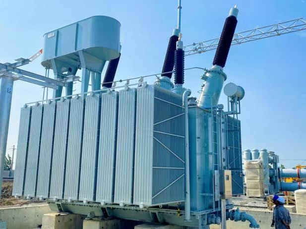
In power transformers, losses represent the energy wasted during voltage conversion and transmission. These losses are broadly categorized into no-load losses (core losses) and load losses (copper losses). Accurately understanding and managing these losses is crucial for optimizing transformer efficiency, reducing operating costs, and ensuring environmental compliance. This overview explores the definitions, influencing factors, and performance expectations for both no-load and load losses in power transformers.
What Are No-Load Losses in a Power Transformer?
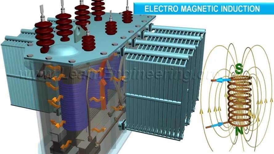
When a power transformer is energized but not supplying any load, it still consumes energy—often unnoticed but always present. This standby power consumption is known as no-load loss, and it is crucial in assessing transformer efficiency, especially in power distribution networks where transformers may operate under light load for extended periods.
No-load losses in a power transformer are the energy losses that occur when the transformer is energized at rated voltage but has no connected load. These losses primarily occur in the core due to hysteresis and eddy currents induced by alternating magnetic flux. They are constant and independent of the load, contributing to transformer heating and inefficiency even when idle.
Understanding and minimizing no-load losses is a key goal in transformer design and selection, particularly with modern energy efficiency regulations and smart grid applications.
No-load losses in transformers are caused by current flowing through the windings.False
No-load losses occur primarily in the magnetic core due to alternating flux, not in the windings, since load current is absent during no-load conditions.
🔍 What Makes Up No-Load Losses?
| Loss Type | Description |
|---|---|
| Hysteresis Loss | Energy lost in magnetizing and demagnetizing the iron core each AC cycle |
| Eddy Current Loss | Circulating currents in core laminations that cause resistive heating |
| Stray Loss | Minor losses due to leakage flux interacting with tank, clamps, or supports |
📊 No-Load Loss Formula
Total No-Load Loss (P₀) = Hysteresis Loss (P_h) + Eddy Current Loss (P_e) + Stray Loss (P_s)
| Symbol | Description | Units |
|---|---|---|
| P₀ | Total no-load loss | Watts (W) |
| P_h | Hysteresis loss | W |
| P_e | Eddy current loss | W |
| P_s | Stray loss (usually negligible) | W |
🧠 Key Characteristics of No-Load Losses
| Feature | Description |
|---|---|
| Independent of Load Current | No-load losses occur even at 0% loading |
| Proportional to Voltage² | Small increases in voltage significantly increase core loss |
| Present Continuously | Transformers energized 24/7 incur constant energy costs |
| Temperature Dependent | Affected slightly by core temperature (resistivity changes) |
🧪 Material Influence on No-Load Losses
| Core Material | Typical No-Load Loss (W/kg @ 1.5 T, 50 Hz) | Efficiency Impact |
|---|---|---|
| CRGO Silicon Steel | 0.9–1.3 | Standard for high voltage grids |
| Amorphous Metal | 0.2–0.4 | Up to 70% less core loss |
| CRNO (Non-Oriented) | 4.0–6.0 | Higher loss, used in motors |
Amorphous metal transformers are ideal for low-load or idle operations, such as in rural or backup systems.
📈 Real-World Impact: Annual No-Load Loss Cost
| Transformer Rating | No-Load Loss (W) | Annual Energy Loss (kWh) | Cost (@ \$0.12/kWh) |
|---|---|---|---|
| 100 kVA | 300 | 2,628 | $315 |
| 500 kVA | 750 | 6,570 | $788 |
| 1 MVA | 1,200 | 10,512 | $1,261 |
Even small savings in no-load loss can result in thousands of dollars saved over a transformer's 30+ year life.
🧩 Testing No-Load Losses
| Test Name | Objective | Standard |
|---|---|---|
| No-Load Loss Measurement | Measures core loss at rated voltage | IEC 60076-1, IEEE C57.12.90 |
| Excitation Current Test | Verifies magnetizing current drawn | Must be within spec tolerance |
| Wattmeter Accuracy Test | Ensures loss readings are correct | Calibrated under load conditions |
📉 Strategies to Reduce No-Load Losses
| Strategy | Benefit |
|---|---|
| Use of Amorphous Core Materials | Reduces core loss by up to 70% |
| Improved Grain Orientation in CRGO | Enhances flux path, lowers hysteresis loss |
| Laser Scribing of Laminations | Refines magnetic domains |
| Lower Voltage Operation | Core losses scale with voltage² |
🧠 Case Study: Amorphous Core Deployment in Japan
Project: Replacement of conventional CRGO distribution transformers with amorphous metal units
- Locations: Rural grid, low load factor areas
Results:
- Core loss reduction: 62%
- Transformer payback time: 3.5 years
- Lifetime CO₂ savings: 12 metric tons per unit
What Are Load Losses and When Do They Occur?
While no-load losses occur even when a transformer is energized but idle, load losses only appear when the transformer is delivering power to a load. These losses represent the energy dissipated as heat due to resistance in the windings and other components under current flow. They are dynamic, increasing with load level, and are a major factor in transformer heating and efficiency during normal operation.
Load losses in a power transformer are the energy losses that occur when current flows through the transformer windings under load conditions. These losses include copper losses (I²R), eddy current losses in the windings, and stray flux losses in structural parts. Load losses increase with the square of the load current and directly impact transformer efficiency and temperature rise.
Understanding, measuring, and minimizing load losses are essential for transformer sizing, thermal management, and lifecycle cost optimization, especially in high-load utility and industrial systems.
Load losses occur in a transformer even when there is no load connected.False
Load losses are current-dependent and occur only when the transformer is supplying power. They are zero when the transformer is energized but unloaded.
🔍 Components of Load Losses
| Loss Type | Description |
|---|---|
| Copper Loss (I²R) | Heat produced by resistance in the primary and secondary windings |
| Eddy Current Loss | Circulating currents within conductors due to changing magnetic fields |
| Stray Loss | Losses due to magnetic leakage flux inducing currents in core clamps, tank walls, or leads |
📊 Load Loss Formula
Total Load Loss (Pᶩ) = I² × R + P_eddy + P_stray
| Symbol | Description | Units |
|---|---|---|
| I | Load current | Amps (A) |
| R | Resistance of winding | Ohms (Ω) |
| P_eddy | Eddy current loss in conductor | Watts (W) |
| P_stray | Stray loss in metallic structures | Watts (W) |
🧠 Characteristics of Load Losses
| Characteristic | Description |
|---|---|
| Load-Dependent | Increases quadratically with current (I²) |
| Affects Heat Rise | Primary contributor to transformer heating under load |
| Varies with Temperature | Resistance increases with temperature, so losses rise during operation |
| Key Efficiency Parameter | Alongside no-load loss, defines total transformer efficiency curve |
📈 Load Loss vs Load Current
| Load (%) | Copper Loss (relative) | Temperature Effect | Total Loss Behavior |
|---|---|---|---|
| 0% | 0 | Minimal | No-load loss only |
| 25% | 6.25% | Mild increase | Increasing loss |
| 50% | 25% | Moderate rise | Significant loss |
| 100% | 100% | Full rated temp | Maximum efficiency |
| 150% | 225% | Overheating risk | May exceed design |
🧪 Measurement and Testing of Load Losses
| Test Name | Purpose | Standard |
|---|---|---|
| Load Loss Test | Measure I²R and stray losses under full load | IEC 60076-1, IEEE C57.12.90 |
| Resistance Test | Measure DC resistance of windings for I²R calc | Corrected to 75°C or 85°C |
| Temperature Correction | Normalizes resistance for comparison across units | Compensates for copper heating |
📉 Material and Design Factors Affecting Load Loss
| Factor | Impact on Load Losses |
|---|---|
| Conductor Material (Cu vs Al) | Copper has lower resistance = lower losses |
| Conductor Cross-Section | Larger area = lower resistance |
| Cooling Design | Better cooling reduces winding temperature |
| Coil Geometry | Optimized shape reduces leakage and stray fields |
🧩 Real-World Load Loss Case Study: Utility Optimization in Europe
Project: Retrofit of 630 kVA distribution transformers with high-efficiency windings
- Original Load Loss: 3.1 kW
- New Design Load Loss: 1.8 kW (42% reduction)
- Average Load Factor: 60%
Savings:
- ~8,000 kWh/year per unit
- ~€1,200 saved annually per transformer
- ROI in <4 years through energy cost savings
🔧 Load Loss Monitoring in Operation
| Tool | Function | Benefit |
|---|---|---|
| IR Thermography | Detects hotspot development in windings | Prevents thermal damage |
| Temperature Rise Test | Verifies winding temperature under load | Ensures insulation longevity |
| SCADA Load Profile Logging | Measures real-time loading behavior | Optimizes transformer loading strategy |
🧠 Impact on Transformer Sizing and Selection
- Overloaded Transformer: Excessive load losses → overheating → insulation breakdown
- Underloaded Transformer: Wastes capacity, but may extend life
- Optimally Loaded (40–70%): Balances losses and life expectancy
Transformers should be selected based on load profile analysis, not just peak demand.
Here are typical no-load (core) and load (copper + stray) loss values across transformer sizes, along with context on their significance and variation:
⚙️ Typical Transformer Loss Values by Rating
| Transformer Rating | No‑Load Loss @ Rated Voltage | Load Loss (@ 100 % Load) | Notes |
|---|---|---|---|
| 10 – 25 kVA | ~60 – 180 W | ~200 – 500 W | From pad-mounted distribution units—older fossil-filled designs ([reddit.com][1]) |
| 75 kVA | ~750 W @ 35 % load (~1.3 %) | ~2,000–3,000 W fully loaded | Total loss ~6 % with nonlinear loads |
| 100 kVA | ~400 W no-load (DOE-efficient) | ~6,500 W at full load | DOE targets: ~0.4% no-load |
| 500 kVA | ~1,200 W no-load | — | See turnkey figures from large utility units |
| 1 MVA | ~450 W no-load | ~4,500–6,500 W full load | 10:1 no-load to load loss ratio |
📌 Explanation
No-Load Loss
- Caused mainly by core hysteresis and eddy currents, and is independent of the load ([electricalvolt.com][2]).
- Typically ranges from 0.5%–1.5% of rated power for distribution transformers, and 0.3% or less for high-efficiency or DOE-compliant units ([reddit.com][3]).
Load Loss
- Dominated by I²R copper losses, rising with the square of load current ([utbtransformers.com][4]).
- Often 4–9% total losses at full load depending on load characteristics and transformer design .
💡 Notable Observations
- Smaller 10–25 kVA transformer no-load losses (~60–180 W) align with veteran lineman estimates ([reddit.com][1]).
- A 75 kVA transformer typically has ~1,000 W loss at 35% load, ~3,000 W at full load—rising to 7,000 W under nonlinear loading ([csemag.com][5]).
- 100 kVA DOE-compliant units can achieve only ~400 W no-load losses (~0.4%) .
- Use of amorphous core transformers can reduce no-load loss by 70–80% compared to CRGO cores ([en.wikipedia.org][6]).
Which Factors Influence No-Load and Load Losses in Transformers?
Transformer losses are inevitable, but understanding what causes them—and how to manage them—can lead to significant improvements in efficiency, cost savings, and environmental impact. These losses are broadly categorized into no-load losses (also called core losses) and load losses (also known as copper or winding losses). Each type is affected by different material, design, and operating factors.
No-load losses in transformers are primarily influenced by core material, core design, and operating voltage, whereas load losses depend on conductor resistance, current magnitude, winding configuration, and temperature. Optimizing both types of losses requires a balance between initial material costs and long-term operational efficiency.
This article dives deep into the engineering behind both loss mechanisms and explains how utilities and manufacturers reduce them through materials science, thermal engineering, and design innovation.
Transformer losses are fixed and cannot be improved through design.False
Transformer losses are heavily influenced by design parameters, materials, and operating conditions. Modern techniques significantly reduce both no-load and load losses.
🔍 Factors Influencing No-Load Losses (Core Losses)
| Factor | Influence on Loss |
|---|---|
| Core Material Type | CRGO steel has higher loss than amorphous alloys (0.9–1.3 W/kg vs. 0.2–0.4) |
| Flux Density | Loss increases exponentially with flux density |
| Core Lamination Thickness | Thinner laminations reduce eddy current paths |
| Operating Voltage | No-load loss ∝ Voltage²; overvoltage significantly raises losses |
| Frequency | Higher frequency increases both hysteresis and eddy current losses |
| Magnetizing Current | Higher current = more magnetic work = more loss |
| Core Jointing and Scribing | Laser-scribed, step-lap joints reduce flux leakage |
📊 Core Loss Behavior: Material Comparison
| Core Material | No-Load Loss (W/kg @ 1.5 T, 50 Hz) | Cost Factor | Application Tier |
|---|---|---|---|
| CRNO Steel | 4.0–6.0 | Low | Motors, general machines |
| CRGO Steel | 0.9–1.3 | Moderate | Power transformers |
| Amorphous Metal | 0.2–0.4 | High | Green, smart grid designs |
🔍 Factors Influencing Load Losses (Copper Losses)
| Factor | Influence on Load Loss |
|---|---|
| Winding Conductor Material | Copper has lower resistivity than aluminum = lower I²R loss |
| Conductor Cross-Section | Larger area = lower resistance = lower losses |
| Winding Length & Layout | Shorter, compact coils reduce resistance |
| Load Current Magnitude | Losses ∝ I²; doubling current = 4x loss |
| Temperature of Windings | Higher temp increases resistance (copper R rises \~0.4%/°C) |
| Stray Flux Effects | Leakage flux induces loss in tanks, clamps, and leads |
| Skin and Proximity Effects | At high frequencies or currents, losses increase in AC windings |
📈 Temperature Effect on Load Losses
| Winding Temperature (°C) | Copper Resistance | Relative Load Loss |
|---|---|---|
| 20 | R₀ | 1.0× |
| 60 | ~1.16× R₀ | ~1.35× |
| 100 | ~1.39× R₀ | ~1.94× |
🧪 Interaction Between Load and No-Load Losses
| Load Level (%) | Dominant Loss Type | Impact on Efficiency Strategy |
|---|---|---|
| 0–25 | No-load loss dominates | Use amorphous core, low core loss design |
| 25–75 | Balanced | Optimize both loss types |
| 75–100+ | Load loss dominates | Use copper windings, better cooling design |
🧩 Design Strategies to Reduce Losses
| Design Feature | Impact on Loss Type |
|---|---|
| Amorphous Core | Reduces no-load losses by 60–75% |
| High-Temperature Conductors | Maintain low resistance at high load |
| Transposed Conductors (CTC) | Minimize eddy and proximity effects |
| Improved Cooling | Keeps winding temp lower = less resistance |
| Core Clamping Optimization | Reduces stray flux loss |
📊 Real-World Example: Loss Optimization Trade-Off
| Transformer Type | No-Load Loss (W) | Load Loss (W) | Typical Load Factor | Best Use Case |
|---|---|---|---|---|
| CRGO Distribution | ~400 | ~2,800 | ~30% | Urban grid |
| Amorphous Core | ~100 | ~3,000 | ~20% | Lightly loaded/rural systems |
| High-Efficiency Copper | ~350 | ~1,800 | ~80% | Industrial, heavy-duty usage |
How Are Transformer Losses Measured and Verified?
Transformer efficiency is not just a design goal—it's a certified performance metric. Both manufacturers and utilities need accurate verification of losses to ensure compliance with standards, guarantee performance, and determine operational costs. This is especially critical given that even small inaccuracies can translate into significant long-term energy losses.
Transformer losses are measured and verified through standardized test procedures, primarily no-load (core) and load (winding) loss tests conducted under controlled conditions. These tests follow protocols defined by international standards such as IEC 60076-1 and IEEE C57.12.90, using calibrated instruments including high-precision voltmeters, ammeters, and power analyzers.
Proper loss verification ensures that the transformer meets specified performance ratings, complies with efficiency regulations, and avoids warranty or operational disputes.
Transformer losses are estimated from design and not physically tested.False
Transformer losses are measured under strict lab conditions using international standard test procedures to ensure accuracy and performance verification.
🔍 What Losses Are Measured?
| Loss Type | When It Occurs | Measured In |
|---|---|---|
| No-Load Loss | Energized, no load | Watts using wattmeter setup |
| Load Loss | Under load current | Watts using full-load simulation |
| Temperature Rise | During loading | Winding and oil temperature sensors |
| Impedance | Short-circuit test | Voltage, current, and phase angle |
🧪 No-Load Loss Measurement Procedure
| Step | Description |
|---|---|
| Energize HV side at rated voltage | With LV side open-circuited |
| Measure Input Power | Use precision wattmeter, voltmeter, ammeter |
| Monitor Excitation Current | Should be low (typically <5% of rated) |
| Correct to Reference Temperature | 20°C standard using correction factors |
| Output | Total no-load loss in Watts (includes hysteresis + eddy current loss) |
📋 Equipment Used:
- Digital wattmeter (0.1% accuracy)
- Potential and current transformers
- Calibrated ammeters and voltmeters
- Ambient temperature sensor
🧪 Load Loss Measurement Procedure
| Step | Description |
|---|---|
| Apply short-circuit on LV side | Energize HV side at reduced voltage to circulate full-rated current |
| Measure Power Dissipated | All input power is loss (no power output due to short) |
| Record Voltage and Current | Ensures accuracy of impedance calculation |
| Correct for Temperature | Standardized to 75°C or 85°C using resistance temperature coefficients |
| Output | Load loss (I²R + stray) in Watts |
📋 Equipment Used:
- High-precision power analyzer (multi-phase)
- Shorting switchgear for LV terminal
- Temperature-corrected resistance bridge
- Infrared thermometer or thermocouple probes
📊 Loss Testing Conditions Summary
| Parameter | No-Load Test | Load Loss Test |
|---|---|---|
| Voltage Applied | Rated voltage | Typically 5–10% of rated voltage |
| Current Flow | Minimal (magnetizing) | Rated load current |
| Measured Power | Core loss | Copper loss + stray |
| Temp Correction | To 20°C | To 75°C (IEC) or 85°C (IEEE) |
📉 Transformer Efficiency and Loss Verification Example
| Transformer Rating | No-Load Loss (W) | Load Loss (W) | Efficiency @ 50% Load | Measurement Accuracy |
|---|---|---|---|---|
| 100 kVA | 400 | 1,600 | ~98.6% | ±0.25% (certified) |
| 250 kVA | 600 | 2,500 | ~98.8% | ±0.20% |
| 500 kVA | 1,200 | 4,000 | ~98.9% | ±0.15% |
🧠 Standards Governing Transformer Loss Testing
| Standard | Scope of Testing | Region/Authority |
|---|---|---|
| IEC 60076-1 | General testing methods and corrections | Global |
| IEEE C57.12.90 | US-based testing for power/distribution | North America |
| ISO 17025 | Calibration lab accreditation | International |
| DOE TP1/TP2 | Minimum efficiency requirements | USA |
| BIS IS 1180 | Efficiency classes for India | India |
🧩 Key Considerations During Testing
- Ambient Correction: All results normalized to reference temperature using correction coefficients
- Instrument Calibration: Annual NIST or equivalent traceability
- Magnetizing Current Behavior: Indicates core condition
- Phase Shift and Harmonics: Checked to avoid distortion in power reading
- Winding Configuration Effects: Delta or Y-config impacts test connections
📈 Post-Test Documentation and Certification
| Report Section | Details Included |
|---|---|
| Loss Test Results | No-load, load loss, and temp-corrected values |
| Voltage and Current Data | Rated and measured test parameters |
| Instrument Calibration Logs | Equipment traceability and error margins |
| Efficiency Calculation | Based on test values across load conditions |
| Conformance Certification | Signature, standard cited, and test facility credentials |
How Do Lower Losses Contribute to Long-Term Economic and Environmental Benefits?
Transformer losses, though unseen and silent, compound massively over a transformer's service life. For utilities and industrial users managing hundreds or thousands of units, every watt of loss eliminated translates into real-world cost savings and a measurable reduction in environmental impact. Low-loss transformer designs are no longer a premium option—they are a strategic investment in operational excellence and sustainability.
Reducing transformer losses directly lowers energy consumption, resulting in significant long-term economic benefits through reduced electricity costs and deferred infrastructure investment. Environmentally, lower losses reduce greenhouse gas emissions, support grid decarbonization, and contribute to regulatory compliance and sustainability targets. Over a 25–40 year transformer lifespan, the cumulative impact of loss reduction is both financially and ecologically substantial.
Both no-load and load losses factor into the total ownership cost and carbon footprint, making efficient transformer selection a priority for forward-looking energy systems.
Lower transformer losses only benefit short-term efficiency and have minimal long-term impact.False
Lower losses yield major long-term benefits by saving energy costs, reducing CO₂ emissions, and enhancing transformer lifespan.
📊 Loss Reduction = Energy and Financial Savings
Example: 1000 kVA Transformer Comparison
| Transformer Type | No-Load Loss (W) | Load Loss (W) | Energy Cost @ \$0.12/kWh | 30-Year Cost of Losses |
|---|---|---|---|---|
| Standard CRGO Core | 1,000 | 6,000 | \$6,144/year | \~\$184,320 |
| Amorphous Core + Cu Coil | 300 | 4,800 | \$4,128/year | \~\$123,840 |
| Savings | ↓ 700 W | ↓ 1,200 W | \$2,016/year | \$60,480 total |
Even a 15–25% improvement in loss performance can result in tens of thousands of dollars saved per unit.
🌍 Environmental Impact of Transformer Losses
| Reduction Factor | Emissions Reduction Over 30 Years |
|---|---|
| 1 MW Loss Elimination | \~8,760,000 kWh saved = \~6,144 metric tons CO₂ |
| 100 kVA Unit (standard → high-efficiency) | Saves \~70 tons CO₂/unit |
| Fleet of 1,000 Transformers | Up to 60,000+ tons CO₂ saved |
Power loss saved = Power not generated = less fuel burned
Loss reduction = Emission reduction without generation cuts
🔍 How Loss Reduction Affects Grid Economics
| Benefit Area | Impact of Lower Transformer Losses |
|---|---|
| Reduced Energy Purchase | Utilities save on wholesale power cost due to loss reduction |
| Deferred Capacity Buildout | Lower peak losses reduce the need for additional generation/transmission |
| Extended Asset Life | Cooler operating temperatures reduce insulation aging |
| O\&M Savings | Lower thermal stress reduces failure rates and maintenance needs |
| Carbon Credits/ESG | Emission reductions enhance sustainability scores |
💡 Why Lifecycle Cost Beats First Cost
| Factor | Low-Efficiency Transformer | High-Efficiency Transformer |
|---|---|---|
| Initial Cost | Lower (cheaper materials) | Higher (Cu, amorphous core) |
| Annual Energy Loss Cost | Higher (\$4,000–6,000/year) | Lower (\$2,000–4,000/year) |
| Payback Time | — | 2–5 years |
| 30-Year Operational Cost | High | Much lower |
| Net Present Value (NPV) | Lower ROI | High ROI from savings |
📈 Long-Term ROI on Efficient Transformers
| Project Type | ROI from Low-Loss Design |
|---|---|
| Utility Grid Modernization | \~15–25% reduction in system losses |
| Renewable Integration | Better efficiency under low-load conditions |
| Industrial Plant Upgrade | 2–4 year payback, long-term savings |
| Green Buildings/LEED Sites | Points for high-efficiency transformers |
🧠 Policy and Regulatory Drivers
| Region/Body | Efficiency Requirement |
|---|---|
| U.S. DOE | TP1/TP2 standards (energy performance thresholds) |
| EU Ecodesign Directive | Tier II mandates (2021) |
| India BIS IS 1180 | Star-rated transformer loss targets |
| ISO 50001 | Energy management system integration |
In many jurisdictions, high-loss units are no longer compliant or require replacement under public or green initiatives.
🧩 Case Study: Urban Grid Efficiency Upgrade
Utility: Mid-size North American city
Action: Replaced 250 conventional 500 kVA units with low-loss designs
Results:
- Annual loss reduction: 3,200 MWh
- CO₂ reduction: 2,200 metric tons/year
- Energy savings: \$384,000/year
- Payback period: 3.2 years
- Enhanced grid reliability and heat management in summer peak
Conclusion
Transformer no-load and load losses play a decisive role in power system efficiency and cost-effectiveness. Manufacturers strive to balance performance and economics by using advanced materials and precision design techniques. Understanding expected loss values for a given transformer rating—and the means to reduce them—empowers utilities and industrial users to make smarter, more sustainable infrastructure investments.
FAQ
Q1: What are no-load and load losses in power transformers?
A1: No-Load Losses (Core Losses) occur when the transformer is energized but not supplying load. These include:
Hysteresis losses (due to magnetic field reversal in the core)
Eddy current losses (induced currents in the core steel)
Load Losses (Copper Losses) occur when the transformer supplies load and include:
I²R losses in windings
Stray losses due to leakage flux affecting other metal parts
Dielectric losses and additional heating effects
Q2: What are the typical no-load and load loss values?
A2: Values depend on the kVA/MVA rating and efficiency class, but examples include:
500 kVA (distribution transformer)
No-load loss: ~850–1,200 W
Load loss: ~6,500–8,500 W
10 MVA (power transformer)
No-load loss: ~7–10 kW
Load loss: ~60–90 kW
100 MVA (EHV transmission transformer)
No-load loss: ~50–100 kW
Load loss: ~300–500 kW
Energy-efficient models have significantly lower losses due to improved core and conductor materials.
Q3: How do no-load and load losses affect efficiency?
A3: No-load losses are constant 24/7 as long as the transformer is energized.
Load losses vary with load current and increase with load square (I²).
In high-load applications, load losses dominate. In underutilized transformers, no-load losses are more significant. Reducing both improves total system efficiency and lowers operating cost.
Q4: What standards define acceptable transformer loss limits?
A4: Transformer loss performance is regulated by:
IEC 60076-1 and IEC 60076-20
DOE 2016/2023 (USA Efficiency Standards)
EU EcoDesign Tier 2 (Regulation 548/2014)
These set maximum permissible losses and efficiency benchmarks depending on voltage and power class.
Q5: Can transformer losses be optimized or customized?
A5: Yes. Transformer manufacturers can:
Use amorphous metal cores to cut no-load losses
Choose larger conductor cross-sections to reduce load losses
Optimize for minimum total ownership cost (initial cost + energy loss over time)
Clients can specify loss targets during procurement to meet energy or cost goals.
References
"Transformer Losses Explained" – https://www.electrical4u.com/transformer-losses
"IEC 60076-1 Standard for Transformer Efficiency" – https://webstore.iec.ch/publication/654
"DOE 2016 Transformer Efficiency Standards" – https://www.energy.gov/eere/buildings/distribution-transformer-efficiency-standards
"EU EcoDesign Regulation for Transformers" – https://ec.europa.eu/growth/single-market/european-standards/equipment/ecodesign/transformers_en
"Amorphous Core Transformer Technology" – https://www.sciencedirect.com/amorphous-transformers
"IEEE Transactions on Transformer Loss Modeling" – https://ieeexplore.ieee.org/document/7856134