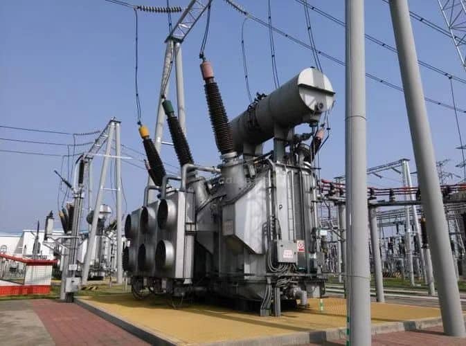
Power transformers are a cornerstone of electrical power systems, particularly in high-voltage transmission networks. Their ability to efficiently transfer electrical energy across long distances makes them vital to modern infrastructure. But beyond their primary function, power transformers offer several operational and economic advantages that justify their widespread use.
How Do Power Transformers Improve Energy Transmission Efficiency?

The global power grid transmits millions of megawatts of electricity every day—yet without one essential component, most of that energy would be lost as heat. Power transformers solve one of the fundamental challenges in electrical engineering: how to move massive amounts of energy over long distances without wasting it. They do this not by generating power, but by transforming voltage and current in ways that make transmission more efficient, economical, and scalable.
Power transformers improve energy transmission efficiency by stepping up voltage at the generation source, which significantly reduces current, thereby minimizing resistive (I²R) losses in transmission lines. Over long distances, this voltage transformation reduces energy loss, lowers conductor size requirements, and improves system power factor. When the energy reaches its destination, transformers step voltage down for safe distribution. This high-voltage, low-current transmission model is the foundation of efficient power grids worldwide.
By using power transformers, we save energy, money, and infrastructure resources—while improving power quality and reliability.
Power transformers reduce transmission losses by stepping up voltage and lowering current in high-voltage lines.True
Energy loss in transmission lines is proportional to the square of the current (I²R). Transformers enable high-voltage, low-current flow to minimize these losses.
Energy transmission losses are unrelated to voltage and transformers have no effect.False
Voltage level directly affects current, and current determines I²R losses. Transformers play a critical role in optimizing this balance.
Why Voltage Matters for Transmission Efficiency
| Electrical Principle | Implication for Transmission |
|---|---|
| $P = VI$ (Power = Voltage × Current) | To transmit a fixed power, increasing voltage allows for reduced current |
| $Loss = I^2 R$ | Reducing current dramatically decreases line losses (heat) |
| High Voltage = Low Current | Lower current → less heat → smaller conductor sizes → higher efficiency |
Increasing voltage using a power transformer is the most effective way to reduce transmission loss.
Transmission Efficiency Before and After Voltage Transformation
| Scenario | Voltage | Current | Line Losses (I²R) | Efficiency |
|---|---|---|---|---|
| Low Voltage (No Transformer) | 11 kV | 9,090 A | High | \~70–80% |
| High Voltage (With Transformer) | 220 kV | 454 A | Very Low | 95–98.5% |
Just increasing voltage by 20× reduces current by the same factor, cutting line losses by 400×.
Core Efficiency Benefits of Power Transformers
| Efficiency Feature | Transformer Role |
|---|---|
| Voltage Step-Up | Reduces current for transmission, cuts resistive losses |
| Voltage Step-Down | Prepares safe voltage for distribution to end-users |
| Tap Changer (OLTC) | Adjusts output voltage to maintain grid voltage stability |
| Low Core and Copper Losses | High-grade CRGO steel and optimized windings minimize internal losses |
| Thermal Management | Advanced cooling prevents overheating, preserves efficiency |
Energy Loss Breakdown Without vs With Transformers
| System Element | Loss Without Transformer | Loss With Power Transformer |
|---|---|---|
| Transmission Lines (I²R) | 15–20% | 1–3% |
| Transformer Core Loss | N/A | 0.2–0.5% |
| Total System Loss | Up to 25% | 2–6% |
The biggest energy savings happen on the transmission lines, thanks to current reduction.
Real-World Example: National Grid Transmission
- Power Transmitted: 300 MW
- Distance: 500 km
- Without Step-Up: 11 kV, 27,272 A → Severe loss, thick conductors
- With Step-Up: 400 kV, 750 A → <3% loss, standard conductor, lower cost
- Transformer Used: 400/220 kV, 500 MVA, ONAF cooled
- Result: 95.7% transmission efficiency maintained
This setup delivers millions in annual energy savings.
Voltage vs Loss Graph
| Voltage Level (kV) | Transmission Loss (%) |
|---|---|
| 11 kV | \~20% over 100 km |
| 66 kV | \~6–8% |
| 132 kV | \~4–6% |
| 220 kV | \~2–4% |
| 400 kV | \~1.5–2% |
| 765 kV (UHV) | <1% |
Higher voltages made possible by power transformers shrink energy loss exponentially.
Additional Efficiency Contributions
| Factor | Efficiency Impact |
|---|---|
| Reactive Power Control (OLTC) | Helps stabilize voltage and reduce transmission loss |
| SCADA-Integrated Monitoring | Prevents overloads and manages loading patterns |
| Load Matching | Maintains operation at high efficiency load points |
Smart transformer control ensures system-wide optimization, not just component-level efficiency.
What Role Do Power Transformers Play in Voltage Regulation?
As power demand fluctuates throughout the day—during peak industrial loads, residential surges, or renewable variability—the voltage in the transmission network tends to shift. If these fluctuations are not corrected, they can cause equipment damage, blackouts, or poor power quality. This is where power transformers with voltage regulation capabilities become indispensable. These transformers are not just passive voltage changers—they are active regulators that help maintain grid stability.
Power transformers play a key role in voltage regulation by using on-load tap changers (OLTCs) or off-circuit tap changers to adjust the transformer's turn ratio and maintain output voltage within acceptable limits despite load fluctuations or grid disturbances. They ensure voltage levels remain stable across the transmission and sub-transmission network, preventing undervoltage or overvoltage conditions that can damage equipment and destabilize the power system.
Voltage regulation is critical for power quality, load performance, and overall system resilience.
Power transformers regulate voltage using tap changers to adjust output under changing load conditions.True
This allows the transformer to maintain consistent voltage despite variations in grid demand or supply.
Power transformers deliver a fixed voltage and cannot regulate output during load changes.False
Most modern power transformers are equipped with OLTCs that allow voltage adjustment without de-energizing the transformer.
1. How Voltage Regulation Works in Power Transformers
| Mechanism | Function |
|---|---|
| Tap Changer (OLTC) | Adjusts the number of active turns in primary or secondary winding while energized |
| Voltage Ratio Change | Increases or decreases output voltage in fine steps (typically ±10%) |
| Automatic Voltage Regulator (AVR) | Controls OLTC based on real-time voltage feedback |
This dynamic adjustment helps keep voltage within ±1% to ±5% of nominal values across varying loads.
2. Voltage Regulation Use Cases
| Application | Voltage Regulation Need |
|---|---|
| Grid Substations | Maintain voltage during regional load changes |
| Industrial Zones | Prevent voltage drop under heavy motor start-up loads |
| Renewable Energy Integration | Adjust for fluctuating solar/wind input |
| Interconnected Grids | Stabilize voltage across multiple utility regions |
Voltage regulation is not optional—it is mandatory for secure and efficient grid operations.
3. OLTC vs DETC Comparison
| Feature | On-Load Tap Changer (OLTC) | De-Energized Tap Changer (DETC) |
|---|---|---|
| Operable Under Load | ✔ Yes | ✘ No (manual adjustment only when off) |
| Typical Use | Transmission/sub-transmission grids | Generation switchyards or stable loads |
| Control | Automatic (via AVR or SCADA) | Manual (during maintenance) |
| Steps | 17–33 steps, ±10–15% total range | 3–5 steps, ±5% |
4. Regulation Example in Practice
- Transformer Rating: 250 MVA, 220/132 kV
- OLTC Range: ±10%, 33 tap positions
- Load Condition: 80% peak → 40% off-peak variation
- AVR Setpoint: 132 kV ±1%
- Performance: Maintained output between 130.7–133.1 kV under dynamic loads
- Control: SCADA-integrated with real-time alerts
The system maintained voltage within 0.8% deviation, avoiding under/overvoltage tripping at customer endpoints.
5. Role in Reactive Power Control
| Concept | Regulatory Function |
|---|---|
| Reactive Power (kVAR) | OLTC helps control power factor and voltage rise/drop |
| Voltage Profile Flattening | OLTC adjusts taps to balance voltage along long feeders |
| Integration with Capacitor Banks | Coordinates switching with tap adjustments |
Power transformers also help manage VAR flows, which are critical for maintaining system voltage integrity.
6. Real-World Benefits of Voltage Regulation
| Benefit | Impact |
|---|---|
| Improved Power Quality | Reduces flicker, undervoltage trips, and overvoltage damage |
| Increased Equipment Life | Stable voltage extends the lifespan of grid and customer equipment |
| Reduced Energy Waste | Optimized voltage reduces I²R losses |
| Better Load Distribution | Maintains equal voltage at parallel load centers |
7. SCADA & Smart Grid Integration
| Monitoring System | Regulation Feature |
|---|---|
| AVR in SCADA System | Set target voltage, deadband, tap delay settings |
| Remote Tap Change Commands | Enable coordinated voltage control across grid |
| Voltage Drop Alarms | Alert operators to tap adjustment needs |
Modern power transformers are fully integrated into smart grid control platforms for live voltage regulation.
How Do Power Transformers Reduce Transmission Losses?
Electricity must travel from distant generation stations to urban and rural consumers—sometimes across hundreds of kilometers. But this journey comes with a cost: transmission losses caused by resistance in conductors. Without intervention, these losses can amount to 10–20% of the total energy produced. Power transformers solve this problem by changing the electrical conditions under which energy travels—stepping up the voltage and reducing current, which is the key to minimizing these resistive losses.
Power transformers reduce transmission losses by stepping up the voltage of generated electricity before it enters the transmission lines, which correspondingly reduces the current. Since resistive losses in conductors are proportional to the square of the current (I²R), this reduction in current dramatically lowers the energy lost as heat during transmission. At the destination, another transformer steps the voltage down for safe distribution and use.
This step-up/step-down voltage transformation system forms the foundation of efficient high-voltage energy transport worldwide.
Power transformers reduce transmission losses by increasing voltage and reducing current, thereby minimizing I²R losses.True
High voltage allows electricity to travel with lower current, reducing resistive heating losses in the transmission conductors.
Power transformers have no effect on transmission losses.False
Without voltage transformation, transmission current would be too high, causing excessive losses and inefficient energy delivery.
Why Current Causes Transmission Losses
| Formula | Explanation |
|---|---|
| $P = VI$ | To transmit fixed power, higher voltage allows for lower current |
| $Loss = I^2R$ | Transmission losses increase quadratically with current |
Cutting current by a factor of 10 reduces losses by a factor of 100.
How Step-Up Transformers Improve Transmission Efficiency
| Stage | Voltage | Current | Result |
|---|---|---|---|
| Generation Output | 11–25 kV | High | Not suitable for long-distance transmission |
| Step-Up Transformer (Power Plant) | 220–400+ kV | Reduced | Current drops drastically, losses minimized |
| Transmission Lines | High Voltage | Low Current | Efficient power flow with minimal heating losses |
| Step-Down Transformer (Substation) | 33–132 kV | Appropriate for distribution | Safe for local networks |
This transformation process is why UHV systems (400 kV–765 kV) are used for cross-country transmission.
Transmission Losses Comparison Example
| Scenario | Low Voltage (No Transformer) | High Voltage (With Transformer) |
|---|---|---|
| Power to Transmit | 100 MW | 100 MW |
| Voltage | 11 kV | 220 kV |
| Current | 9,090 A | 455 A |
| Resistance (Line Total) | 0.2 Ω/km | 0.2 Ω/km |
| Loss (I²R over 100 km) | \~165 MW (!) | \~4.1 MW |
| Efficiency | <40% | >95% |
Without power transformers, long-distance power transmission would be inefficient and economically unsustainable.
Voltage Level vs. Transmission Loss Chart
| Voltage Level (kV) | Typical Transmission Loss (%) over 100 km |
|---|---|
| 11 kV | 18–22% |
| 33 kV | 10–15% |
| 66 kV | 6–9% |
| 132 kV | 4–6% |
| 220 kV | 2–4% |
| 400 kV | 1–2% |
| 765 kV | <1% |
Higher voltage = lower current = lower line loss.
Real-World Application: 500 MVA Transmission Link
- Source: Thermal power plant, 11 kV generator output
- Step-Up Transformer: 11/400 kV, 500 MVA, ONAN/ONAF type
- Line Distance: 500 km
- Loss Reduction: From \~20% (at 33 kV) to <2% (at 400 kV)
- Annual Energy Savings: >\$4 million at \$0.10/kWh equivalent
Power transformers reduce the need for thick, costly conductors and increase total transmitted energy volume.
Other Transformer Features That Improve Transmission Efficiency
| Design Feature | Efficiency Impact |
|---|---|
| High-Grade Core (CRGO Steel) | Minimizes eddy current and hysteresis losses |
| Copper/Aluminum Windings | Designed for minimal I²R loss under load |
| Forced Cooling Systems | Maintains thermal stability under high load |
| On-Load Tap Changer (OLTC) | Regulates voltage to prevent under/overvoltage losses |
Internal transformer efficiency is typically above 98.5%, with well-managed losses.
Why Are Power Transformers Economical for Long-Distance Transmission?
Building and maintaining transmission lines is one of the most expensive tasks in the power sector. Without efficient planning, long-distance energy transport can drain financial resources through excessive energy losses, oversized conductors, and costly infrastructure. Fortunately, power transformers make long-distance transmission not only feasible—but economical. Their ability to step up voltage and reduce current enables utilities and governments to minimize both operational and capital costs across the life cycle of a grid.
Power transformers are economical for long-distance transmission because they increase voltage, which significantly reduces current, thereby cutting I²R losses and allowing for the use of smaller, less expensive conductors. This reduces transmission line costs, energy loss expenses, and infrastructure requirements. Over time, the high efficiency enabled by power transformers results in lower energy waste and more affordable power delivery, making them a cost-effective solution for high-voltage, long-distance networks.
Without power transformers, transmitting electricity across large regions would require larger conductors, more substations, and higher energy generation—making it prohibitively expensive.
Power transformers reduce transmission costs by enabling high-voltage, low-current flow that minimizes energy loss and conductor size.True
Stepping up voltage reduces current, and since energy loss and conductor cost scale with current, transformers make long-distance transmission more economical.
Using power transformers increases the cost of transmission infrastructure over long distances.False
Transformers reduce both initial capital costs and long-term operational losses, making them a financially efficient investment.
1. Voltage Increase = Current Decrease = Cost Savings
| Transmission Principle | Economic Benefit |
|---|---|
| $P = V \times I$ | For the same power, increasing voltage reduces current |
| $Loss = I^2 \times R$ | Lower current drastically cuts energy losses |
| Conductor Size ∝ Current | Reduced current allows smaller, cheaper conductors |
A tenfold increase in voltage allows for a tenfold decrease in current, which reduces losses by 100× and cuts conductor size by more than 50%.
2. Cost Comparison: Low Voltage vs High Voltage Transmission
| Parameter | Low Voltage (e.g., 33 kV) | High Voltage (e.g., 220 kV) |
|---|---|---|
| Current (for 100 MW) | \~3,030 A | \~455 A |
| Conductor Size Required | 500–700 mm² | 150–250 mm² |
| Line Losses (100 km) | \~12–15% | \~2–3% |
| Energy Cost (per year) | \$5M+ | <\$1M |
| Line Structure Cost | Larger towers, more spacing | Compact towers, fewer lines |
Using a power transformer to step up voltage can reduce total project costs by 30–60% over 20 years.
3. Transformer Cost vs Savings Over Lifecycle
| Component | Cost (USD) |
|---|---|
| Power Transformer (e.g., 220/400 kV, 250 MVA) | \~\$1.5–2M |
| Annual Energy Loss Savings | \$200,000–\$1M/year |
| Payback Time | 2–5 years (avg.) |
| Lifetime Savings (30 years) | \$6–15M+ |
Power transformers have a short payback period and provide decades of compounding savings.
4. Fewer Substations and Support Infrastructure
| Without High Voltage | With Power Transformers |
|---|---|
| More substations needed for boost | Voltage stepped up at generation and sustained long-distance |
| Frequent boosting to counter losses | One-time boost sufficient due to reduced current |
| Higher land and construction cost | Compact network with fewer installations |
Fewer substations = lower land use, civil work, and maintenance costs.
5. Example: National Transmission Corridor
- Route: 600 km, from coastal generation to inland grid
- Without Step-Up: Needed 4 substations, heavy conductors, 15% loss
- With Transformers: 400 kV system, 2 substations, 2.5% loss
Cost Difference:
- Capital: Saved \~\$30M in line hardware
- Operating: Saved \$50M in energy over 25 years
- Total ROI: >400% on transformer investment
This case showed that transformers enabled grid-scale economics and sustainable scalability.
6. Summary Table: Why Power Transformers Are Economical
| Factor | Economic Advantage |
|---|---|
| High Voltage Operation | Lowers current → lower loss and smaller conductors |
| Reduced Energy Losses | Saves millions in annual energy waste |
| Smaller Conductor and Tower Size | Lowers material and installation cost |
| Fewer Intermediate Substations | Reduces infrastructure duplication |
| Long Asset Life (30–40 years) | Delivers compounding ROI |
| Load Flexibility | Supports grid expansion without major new investments |
How Do Power Transformers Support Grid Stability and Load Balancing?
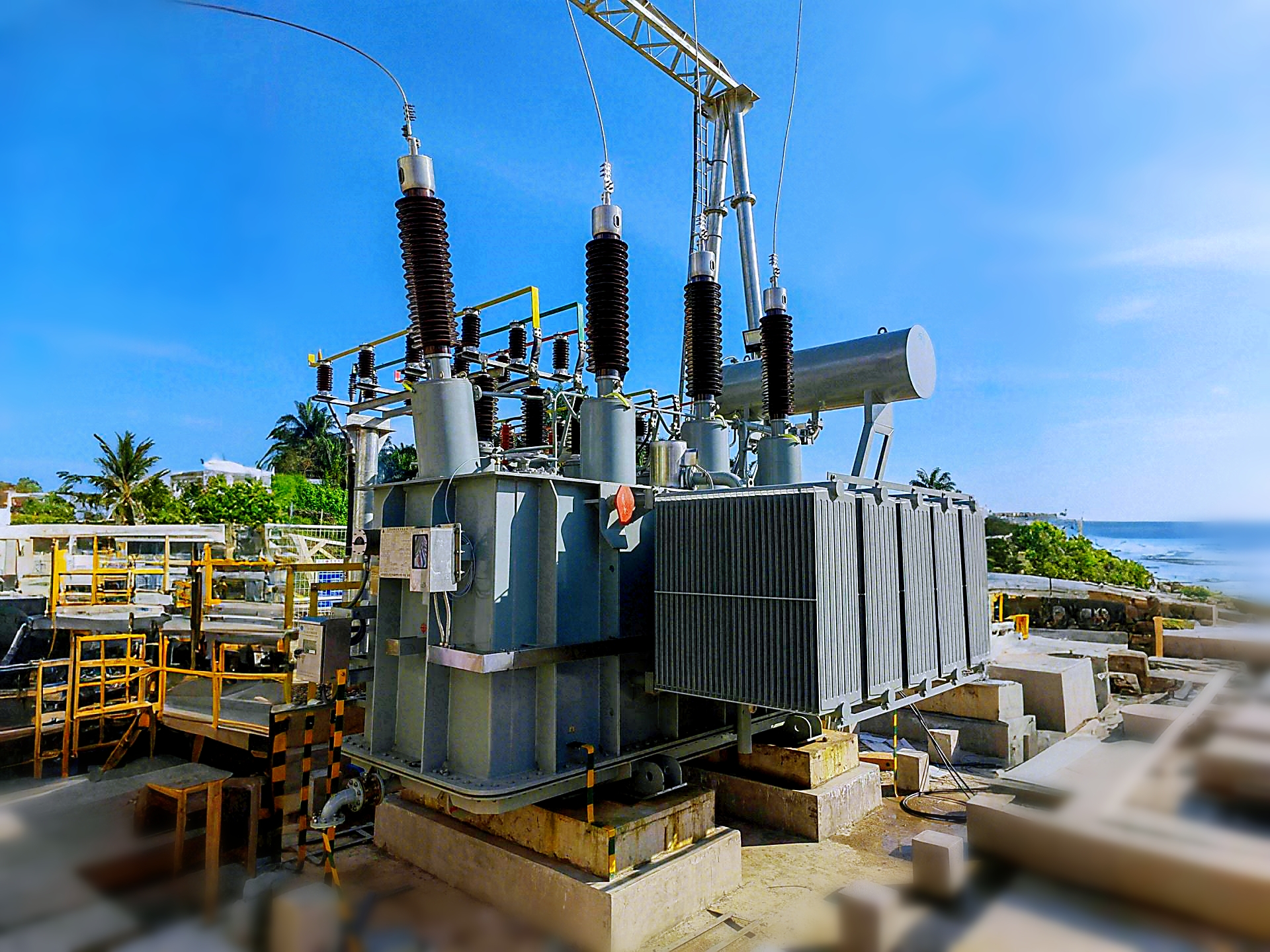
![]()
In modern power systems, where electricity demand fluctuates by the second and generation is increasingly variable (especially with renewables), maintaining a stable and balanced grid is more challenging than ever. The failure to do so can result in blackouts, equipment damage, or cascading faults. Power transformers play a silent but vital role in countering this instability. Through voltage regulation, load sharing, fault isolation, and interregional interconnection, they help utilities manage a constantly shifting grid with precision and resilience.
Power transformers support grid stability and load balancing by regulating voltage levels, managing real and reactive power flows, and enabling interconnection between different grid segments. On-load tap changers (OLTCs) allow real-time voltage adjustments to match load conditions, while transformers help distribute loads evenly across substations and isolate disturbances during faults. This stabilizes frequency, voltage, and power quality across the entire transmission system.
They are essential not only for moving electricity—but for controlling its behavior in complex, interconnected power systems.
Power transformers help maintain grid stability and load balancing by regulating voltage and enabling regional interconnection.True
They allow utilities to adjust voltage, redistribute loads, and isolate faults, which are essential for a resilient and stable power system.
Power transformers have no influence on grid stability or load balancing.False
Without transformers, voltage fluctuations and load imbalances would cause system instability and frequent outages.
1. Voltage Regulation for Grid Stability
| Condition | Transformer Role |
|---|---|
| Load Increase | OLTC lowers tap position to maintain voltage |
| Load Decrease | OLTC raises tap position to prevent overvoltage |
| Long Feeder Voltage Drop | Adjusts voltage at sending end to ensure stable delivery |
| Fluctuating Renewable Output | Stabilizes voltage with AVR-controlled tap changes |
Power transformers equipped with on-load tap changers (OLTCs) adjust output voltage in real time to maintain grid stability.
2. Load Balancing Across Regions
| Scenario | Transformer Function |
|---|---|
| Urban area under peak load | Supplies excess power from adjacent lower-load zones |
| Uneven industrial demand | Redistributes current via transformer interconnection |
| Grid reconfiguration | Transfers load to redundant substations through transformer switches |
Load balancing minimizes overloads, overheating, and voltage collapse.
3. Reactive Power and Frequency Control
| Grid Behavior | Transformer Contribution |
|---|---|
| Low Voltage (High Reactive Demand) | OLTC steps up voltage to improve power factor |
| High Voltage (Low Load) | OLTC steps down to control overvoltage |
| Frequency Drop (Overload) | Transformer supports generator response by maintaining voltage at bus |
By managing reactive power, transformers help keep system frequency and voltage in sync.
4. Fault Isolation and Disturbance Control
| Fault Type | Transformer Protection Response |
|---|---|
| Internal fault | Trips via differential protection (87T relay) |
| External grid fault | OLTC holds tap position or isolates feeder |
| Cascading voltage drop | Transformer acts as a buffer to limit spread |
Power transformers can block, isolate, or localize disturbances, helping prevent full-grid blackouts.
5. Regional Interconnection and Flexibility
| Transformer Intertie | Stability and Load Benefits |
|---|---|
| 400/220 kV grid tie | Balances load between national and regional grids |
| 220/132 kV substation bridge | Smooths transitions between urban and rural demand |
| International HV interconnects | Stabilizes cross-border power trading |
Power transformers enable multi-level and cross-region grid harmonization.
Example: Grid Stability in Practice
- Substation Type: 400/220 kV transmission node
- Transformer: 315 MVA, OLTC-equipped, ONAF cooled
- Load Condition: Fluctuating demand (120–290 MVA)
- OLTC Response: Maintained ±1% voltage deviation over 24-hour cycle
- Control System: AVR + SCADA with automatic tap control
- Result: Zero outages, balanced voltage across 3 substations
The transformer ensured real-time adaptability to load variability, preventing under- and overvoltage trips.
6. Smart Grid and Monitoring Integration
| Technology | Function in Grid Stability |
|---|---|
| SCADA Control | Remote tap change and voltage setpoint adjustments |
| WAMS (Wide Area Monitoring System) | Tracks system frequency and voltage in real time |
| PMUs (Phasor Measurement Units) | Detect instability and prompt transformer adjustments |
| AI-Based Tap Optimization | Predictive tap control based on load trends |
Digital monitoring tools help transformers respond faster and more accurately to grid changes.
Summary Table: How Power Transformers Enhance Grid Stability
| Function | Stability Contribution |
|---|---|
| Voltage Regulation | Keeps bus voltage within standard range |
| Load Sharing | Distributes power to prevent overloads |
| Frequency Response | Supports balance during frequency dips or surges |
| Fault Containment | Limits fault spread, protects upstream/downstream |
| Grid Interconnection | Facilitates power routing between segments |
| Reactive Power Management | Enhances voltage control and power factor |
What Is the Longevity and Reliability Advantage of Power Transformers?
In electrical infrastructure, reliability isn’t a luxury—it’s a necessity. A single failure in a high-voltage transmission transformer can interrupt power to millions, cost utilities millions more, and trigger cascading outages across entire regions. That’s why power transformers are engineered for extreme reliability and decades-long service life. They are designed to operate under continuous load, high thermal stress, environmental exposure, and fault pressure—all without frequent failure or excessive maintenance.
Power transformers offer longevity and reliability advantages due to their robust design, high-quality insulation systems, durable construction materials, and integrated protection features. When maintained properly, they can last 30 to 40 years or more with a failure rate of less than 1% per year. Their high mean time between failures (MTBF), coupled with condition monitoring systems and scheduled maintenance, ensures uninterrupted service in critical infrastructure for decades.
These long-life assets are essential for utilities and industries seeking both performance and cost-efficiency over the long haul.
Power transformers are designed to last 30 to 40 years with high reliability and minimal failure rates.True
Their construction materials, insulation systems, and preventive maintenance protocols support long-term durability.
Power transformers require frequent replacement due to short lifespans and poor reliability.False
With proper design and maintenance, they are among the most durable components in the power grid, often lasting decades.
1. Typical Service Life and Durability Standards
| Parameter | Typical Power Transformer Value |
|---|---|
| Expected Lifespan | 30–40 years (standard); up to 50+ years in ideal conditions |
| Mean Time Between Failures (MTBF) | 150,000 to 300,000 hours |
| Insulation Aging Time | Designed for 180,000+ hours at rated temperature |
| Core & Tank Durability | Resistant to mechanical stress, corrosion, vibration |
These metrics make transformers among the most durable capital assets in a utility’s infrastructure portfolio.
2. Factors That Enhance Longevity
| Design Element | Longevity Contribution |
|---|---|
| High-grade insulation | Withstands thermal stress for decades |
| CRGO Steel Core | Reduces heat and aging due to eddy current and hysteresis |
| Oil or Ester Fluids | Provide superior cooling, dielectric protection, and longevity |
| Cooling Systems (ONAN/ONAF) | Prevent overheating and extend insulation life |
| Robust Tank and Seals | Prevent oil leaks and environmental degradation |
Use of natural esters or inhibited mineral oil can further enhance transformer aging resistance and reduce maintenance frequency.
3. Reliability Through Redundant Systems and Protection
| Protection Feature | Reliability Benefit |
|---|---|
| Buchholz Relay | Detects early internal faults before catastrophic failure |
| Pressure Relief Device (PRD) | Prevents tank rupture during internal arcing |
| RTDs & Thermal Sensors | Monitor winding and oil temperature in real time |
| Differential Protection (87T) | Fast detection of winding short circuits |
| SCADA/Online DGA | Predictive condition monitoring to avoid failure |
These systems ensure transformers can self-isolate or trigger alarms long before critical failure occurs.
4. Maintenance and Monitoring for Reliability
| Maintenance Task | Interval | Impact on Longevity |
|---|---|---|
| Oil Testing (DGA, Moisture) | Semi-annual or annual | Detects insulation degradation early |
| Thermal Imaging | Quarterly | Identifies hotspots and loose connections |
| OLTC Inspection & Cleaning | Every 3–5 years | Prevents arcing, contact wear |
| Radiator and Cooling Check | Annual | Ensures optimal heat dissipation |
| Bushing Testing | Annually | Prevents dielectric breakdown |
Proactive maintenance boosts lifespan by 10–15 years and reduces the likelihood of failure by over 70%.
5. Failure Rate and Aging Curve
| Transformer Age | Failure Rate (%) |
|---|---|
| 0–10 years | <0.5% (infant mortality due to design or manufacturing issues) |
| 10–30 years | <1% per year (steady-state phase) |
| 30–40+ years | 2–4% per year (aging failure mode begins) |
Properly managed units may surpass 40 years without any major failure.
6. Real-World Case Study: 35-Year Continuous Operation
- Transformer: 315 MVA, 400/220 kV
- Installed: 1988, thermal plant switchyard
- Design Features: ONAN/ONAF cooling, high-quality oil, OLTC
- Upgrades: Digital relays added in 2010, oil reprocessed in 2015
- Failures: None
- Current Condition: 98% performance efficiency, life extended to 45+ years
This unit provides proof that robust design + diligent maintenance = decades of reliable service.
7. Benefits of Long Transformer Lifespan
| Advantage | Outcome |
|---|---|
| Lower Replacement Costs | Avoid frequent capital expenditures |
| Grid Reliability | Stable operation with minimal unplanned outages |
| High Uptime | Ensures availability for critical load zones |
| Asset Depreciation Benefits | Spread costs over a longer financial timeline |
| Environmental Benefits | Less material waste and fewer disposal cycles |
Over its lifetime, a single power transformer can safely transfer billions of kilowatt-hours of energy.
Conclusion
Power transformers offer a range of advantages—from enhancing transmission efficiency and minimizing energy loss, to ensuring voltage stability and supporting grid resilience. Their design enables high-capacity operation with a long service life, making them a cost-effective and dependable solution in national power grids and industrial settings. Understanding these benefits helps stakeholders make informed decisions in infrastructure planning and energy system management.
FAQ
Q1: What are the main advantages of a power transformer?
A1: Power transformers offer several essential advantages:
Efficient voltage conversion for long-distance transmission
Reduction of energy loss by stepping up voltage and lowering current
Stable and reliable operation in constant load conditions
High efficiency (98–99%) under full load
Support for grid expansion and interconnection
Q2: How do power transformers reduce energy losses?
A2: Power transformers step up the voltage for transmission, which lowers the current. Since power loss due to resistance (I²R loss) depends on current, this significantly reduces transmission losses, making long-distance energy transfer more efficient.
Q3: What role do power transformers play in grid stability?
A3: Power transformers:
Maintain voltage levels across regions
Enable interconnection between grids and substations
Facilitate load balancing and frequency control
This enhances the resilience and reliability of the entire electrical system.
Q4: Are power transformers suitable for high-load applications?
A4: Yes. Power transformers are built to handle large loads continuously at high voltages, making them ideal for generation plants, transmission networks, and heavy industries.
Q5: Can power transformers integrate renewable energy sources?
A5: Absolutely. Power transformers step up voltage from solar farms, wind parks, and hydro plants to grid-compatible levels, supporting clean energy integration and modern energy strategies like the smart grid.
References
"Advantages of Power Transformers" – https://www.transformertech.com/advantages-of-power-transformers
"Why Power Transformers Are Critical to Energy Efficiency" – https://www.electrical4u.com/benefits-of-power-transformers
"Efficiency and Role of Power Transformers in Grids" – https://www.powermag.com/power-transformer-efficiency
"Energy Central: The Value of Power Transformers in Infrastructure" – https://www.energycentral.com/c/ee/power-transformer-benefits
"Smart Grid News: Advantages of High Voltage Transformers" – https://www.smartgridnews.com/benefits-power-transformers
"ResearchGate: High-Efficiency Operation of Power Transformers" – https://www.researchgate.net/power-transformer-efficiency-study
"ScienceDirect: Transformer Technology and Grid Optimization" – https://www.sciencedirect.com/power-transformer-benefits
"PowerGrid: Key Benefits of Using Power Transformers" – https://www.powergrid.com/advantages-of-power-transformers