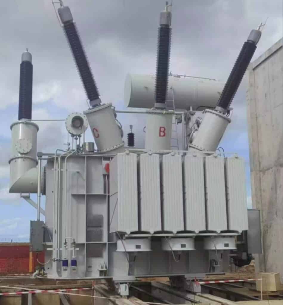
Power transformers play a vital role in stepping up or stepping down voltage levels in high-voltage power systems. The voltage range of these transformers determines where and how they’re used—especially in generation plants, transmission lines, and substations. Understanding this range is key to designing and maintaining reliable electrical infrastructure.
What Defines a Power Transformer by Voltage Rating?
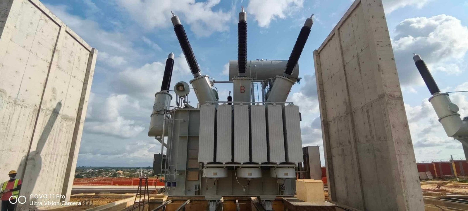
Not all transformers are built for the same job. From tiny devices in chargers to massive grid-scale machines, transformers vary based on their function and voltage capacity. In the power sector, a transformer’s voltage rating is one of the primary characteristics that determines its classification. While distribution transformers handle low-voltage needs, power transformers are defined by their ability to operate at high voltages—starting at 33 kV and extending up to ultra-high voltage (UHV) levels of 765 kV and beyond.
A power transformer is defined by voltage rating as a transformer that operates at or above 33 kilovolts (kV), typically within transmission or sub-transmission systems. These units handle high-voltage input and output to enable long-distance, efficient energy transmission. Common voltage ratings for power transformers include 66 kV, 132 kV, 220 kV, 400 kV, and 765 kV, and are selected based on grid requirements, power flow levels, and national transmission standards.
Their voltage classification reflects their role in high-capacity, high-stability electrical networks.
Power transformers are defined by voltage ratings of 33 kV and above, typically used in transmission networks.True
This threshold separates power transformers from lower-voltage distribution units, aligning with industry classification and grid design.
Transformers below 33 kV are considered power transformers.False
Transformers under 33 kV are generally categorized as distribution or industrial transformers, not power-class units.
Voltage Rating Classification: Where the Threshold Lies
| Transformer Type | Voltage Rating Range | Typical Use |
|---|---|---|
| Control / Instrument Transformer | 110 V – 11 kV | Protection, metering, electronics |
| Distribution Transformer | 3.3 kV – 33 kV | Local power delivery to homes and businesses |
| Power Transformer | ≥ 33 kV (typically 66–765 kV) | Transmission, substation, intertie |
| UHV Transformer | 800 kV – 1200 kV | Bulk interstate or intercontinental systems |
The 33 kV threshold is recognized globally (e.g., IEEE, IEC, IS standards) as the baseline for power transformer classification.
Common Voltage Ratings and Grid Roles
| Voltage Rating (kV) | Transformer Function | Typical Location |
|---|---|---|
| 66 kV | Sub-transmission, industrial intertie | Regional substations, large industries |
| 132 kV | Transmission step-down | Grid interface substations |
| 220 kV | Inter-regional grid interconnect | National grid corridors |
| 400 kV | Main transmission backbone | High-load and export/import corridors |
| 765 kV | Ultra-high-voltage long-haul transport | Cross-border and bulk transmission routes |
The higher the voltage, the greater the transmission efficiency and power transfer capacity.
Design Implications by Voltage Rating
| Voltage Class | Design Consideration |
|---|---|
| Up to 132 kV | Conventional insulation, oil-immersed tanks |
| 220–400 kV | Enhanced dielectric design, radiators, OLTC |
| 765 kV and above | Composite bushings, increased creepage distances, forced cooling |
Voltage rating determines not just the electrical parameters, but also cooling, insulation, and tank design.
Voltage vs Application Matrix
| Voltage (kV) | Input/Output Role | Application Type |
|---|---|---|
| 66 / 33 kV | Step-down to distribution | Receiving substation |
| 132 / 66 kV | Step-down or interconnection | City/regional transmission node |
| 220 / 132 kV | Step-down at regional interface | Long-distance transmission termination |
| 400 / 220 kV | Step-down at national grid node | Bulk grid interconnection and regulation |
| 765 / 400 kV | Step-down at UHV corridors | Super-grid export to lower-voltage systems |
Real-World Use Case Example
- Transformer Type: 400/220 kV, 500 MVA, ONAF cooled
- Voltage Class: High-voltage (HV), power-class
- Installed At: National transmission substation
- Function: Balances power between 400 kV interstate lines and 220 kV regional feeders
- Impact: Delivers stable voltage to 5+ million residential and industrial users
The transformer's voltage rating defines its integration point in the grid and its power handling role.
Regulatory and Design Standards by Voltage
| Standard | Voltage Scope | Applies To |
|---|---|---|
| IEC 60076 Series | 72.5 kV and above | Global design and test compliance |
| IEEE C57 Standards | 69 kV and above | North American transformer definitions |
| IS 2026 (India) | 66 kV and above | Indian power transformer classification |
These standards ensure consistency in classification, safety margins, and insulation levels.
What Is the Typical High-Voltage Range for Power Transformers?
Power transformers are the cornerstones of high-voltage power transmission systems, enabling electricity to travel long distances efficiently by stepping up voltage at generation points and stepping it down near end users. Their voltage range isn’t random—it’s standardized and specifically tailored to meet the demands of national and international grid infrastructures. Understanding their typical high-voltage range is critical for system design, safety compliance, efficiency optimization, and equipment selection.
The typical high-voltage range for power transformers starts at 66 kV and extends up to 765 kV. These transformers are used at key points in transmission networks, such as generation step-up stations, inter-regional substations, and high-voltage grid interconnections. The most common standardized high-voltage levels include 66 kV, 110 kV, 132 kV, 220 kV, 400 kV, and 765 kV, with each voltage tier serving specific grid segments based on distance, load size, and geographic distribution.
These voltage levels align with international standards like IEC 60076, IEEE C57, and IS 2026, ensuring global interoperability and safety.
Power transformers typically operate at high-voltage levels from 66 kV up to 765 kV for transmission applications.True
This voltage range allows efficient long-distance energy transmission with minimal loss, supporting large-scale grid infrastructure.
Power transformers operate below 33 kV and are mainly used in residential power systems.False
Transformers below 33 kV are categorized as distribution transformers. Power transformers operate at significantly higher voltages.
Standardized High-Voltage Ranges for Power Transformers
| Voltage Rating (kV) | Classification | Typical Application |
|---|---|---|
| 66 kV | Sub-transmission | Regional step-down for industrial or city zones |
| 110 kV | Sub-transmission/Primary | Urban load centers, utility substations |
| 132 kV | Transmission | Grid interconnection and regional substations |
| 220 kV | High transmission | National inter-regional lines |
| 400 kV | Ultra-high transmission | Backbone transmission for large-scale grids |
| 500 kV | Extra high-voltage (EHV) | Long-distance HV corridors (common in the U.S.) |
| 765 kV | UHV transmission | Bulk interstate or intercontinental networks |
These voltage levels are selected based on distance, power capacity, and fault-level management.
Voltage vs Transmission Distance Table
| Voltage Level | Typical Distance (km) | Efficiency Benefit |
|---|---|---|
| 66 kV | Up to 50 km | Short regional transmission |
| 132 kV | 50–150 km | Moderate loss reduction |
| 220 kV | 100–300 km | Excellent for inter-city transmission |
| 400 kV | 300–600+ km | Minimal I²R loss for bulk power |
| 765 kV | 500–1000+ km | Maximum efficiency, minimal line loss |
Higher voltage = lower current, which = lower I²R (resistive) losses and greater transmission economy.
Real-World Transformer Examples by Voltage
| Transformer Voltage Rating | Power Rating (MVA) | Application Example |
|---|---|---|
| 66/11 kV | 20–40 MVA | Large industrial plant or sub-transmission |
| 132/33 kV | 50–160 MVA | Regional grid step-down transformer |
| 220/132 kV | 100–250 MVA | State or city grid interface transformer |
| 400/220 kV | 315–630 MVA | National backbone grid intertie |
| 765/400 kV | 500–1200 MVA | UHV grid and long-distance bulk power transport |
These units are commonly installed in generation switchyards, major substations, and HVDC terminals.
Voltage Standards Reference
| Standard | Governing Body | Applicable Voltage Ranges |
|---|---|---|
| IEC 60076 Series | International | 72.5 kV to 1200 kV |
| IEEE C57.12.00 | North America | 69 kV to 765 kV |
| IS 2026 (India) | India | 66 kV to 800 kV |
These standards ensure design consistency, safety margins, and performance expectations across grids worldwide.
Why This Voltage Range Matters
| Design Consideration | High Voltage Advantage |
|---|---|
| Transmission Loss (I²R) | Reduced dramatically at high voltage |
| Conductor Size & Cost | Smaller conductors can carry same power |
| Fault Current Limitation | Enhanced with higher voltage isolation |
| Infrastructure Scalability | High voltage enables large power blocks per line |
| Equipment Standardization | Enables transformer interoperability in global grids |
This makes power transformers at 220–400–765 kV levels critical for growing, stabilizing, and connecting modern power networks.
How Do Step-Up and Step-Down Power Transformers Differ in Voltage?
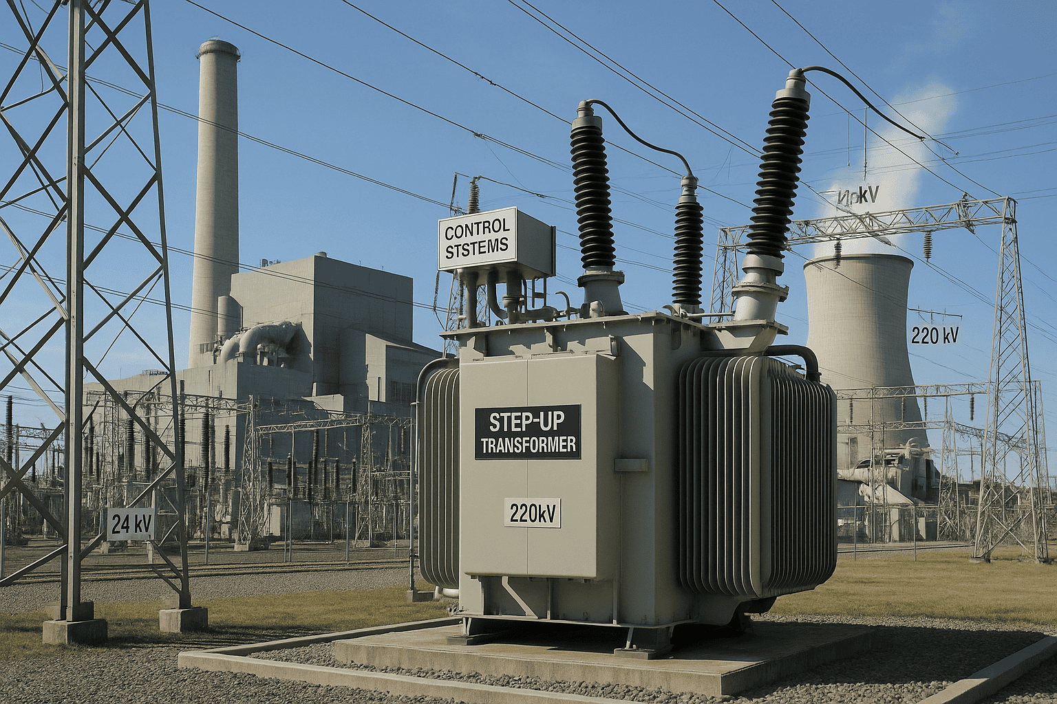
Power transformers are essential tools in high-voltage electricity networks, but not all power transformers perform the same role. The key distinction lies in how they transform voltage. While all transformers operate on the principle of electromagnetic induction, their input and output voltage configurations define them as either step-up or step-down. This distinction is foundational to the function of a safe, efficient, and balanced power grid.
Step-up power transformers increase voltage from a lower input (typically from a generator) to a higher output suitable for transmission, while step-down power transformers decrease high transmission voltages to lower levels appropriate for distribution or utilization. The voltage ratio between primary and secondary windings is the core difference, with step-up transformers having fewer turns on the primary side and more on the secondary, and step-down transformers having the opposite.
These voltage transformations support both long-distance transmission and safe energy delivery at the consumption point.
Step-up transformers increase voltage for transmission, while step-down transformers reduce it for distribution or use.True
The primary and secondary winding configurations are designed to either raise or lower voltage according to grid requirements.
Step-up and step-down transformers have the same voltage function and are interchangeable.False
They serve distinct roles based on voltage direction and cannot be swapped without redesigning the entire power system.
Voltage Function Comparison: Step-Up vs Step-Down
| Transformer Type | Primary Voltage | Secondary Voltage | Voltage Action | Grid Role |
|---|---|---|---|---|
| Step-Up Transformer | Low (11–25 kV) | High (132–400+ kV) | Voltage increased | Generator to transmission line |
| Step-Down Transformer | High (132–765 kV) | Low (33–11–0.4 kV) | Voltage reduced | Substation to local grid |
Step-up units are used at generation switchyards, while step-down units are common at receiving substations and distribution points.
Winding Configuration Difference
| Design Element | Step-Up Transformer | Step-Down Transformer |
|---|---|---|
| Primary Coil Turns | Fewer turns | More turns |
| Secondary Coil Turns | More turns | Fewer turns |
| Turns Ratio (Ns/Np) | Greater than 1 | Less than 1 |
| Power Direction | Source → Grid | Grid → End-user or local zone |
$$\frac{V_s}{V_p} = \frac{N_s}{N_p}$$
This formula governs voltage transformation, where increasing turns increases voltage and vice versa.
Practical Examples
| Application | Transformer Type | Input Voltage | Output Voltage |
|---|---|---|---|
| Thermal Power Plant Output | Step-Up | 13.8 kV | 400 kV |
| Wind Farm Collector Substation | Step-Up | 33 kV | 132 kV |
| Regional Transmission Substation | Step-Down | 400 kV | 132 kV |
| City Distribution Entry Point | Step-Down | 132 kV | 33/11 kV |
Each transformer type is custom-engineered for voltage levels and system directionality.
Voltage Range Guide by Transformer Function
| Transformer Role | Voltage Conversion Range (Typical) |
|---|---|
| Step-Up for Transmission | 11–25 kV → 132–400 kV |
| Step-Up for Renewable Input | 33 kV → 132 kV |
| Step-Down for Distribution | 400 kV → 132/66/33/11 kV |
| Final Step-Down to End-User | 11 kV → 400/230 V |
Some multi-winding transformers may serve hybrid step-down purposes at intermediate stages.
Substation Configuration Overview
| Substation Type | Transformer Role | Voltage Behavior |
|---|---|---|
| Generation Switchyard | Step-Up | Boosts voltage for long-distance |
| Transmission Substation | Step-Down | Matches voltage between networks |
| Receiving Substation | Step-Down | Reduces voltage for distribution |
| Renewable Collector Yard | Step-Up | Prepares energy for transmission |
Design and Cooling Differences
| Feature | Step-Up Transformer | Step-Down Transformer |
|---|---|---|
| Voltage Stress | Higher on secondary side | Higher on primary side |
| Cooling Type | OFAF/ONAF for generator connection | ONAN/ONAF in urban substations |
| Protection Focus | Generator synchronization, surge arresters | Load-side fault isolation and stability |
Voltage transformation direction affects insulation thickness, bushing design, and winding spacing.
What Are Common Voltage Levels in National Grids (e.g., 110 kV, 220 kV, 400 kV)?
Power systems across the globe rely on standardized high-voltage levels to deliver electricity efficiently and safely over long distances. These voltages aren’t arbitrary—they’re chosen based on a balance of technical performance, infrastructure cost, and grid reliability. From 66 kV to 765 kV, each voltage level plays a specific role in the transmission and distribution network. Understanding these levels is essential for designing substations, selecting transformers, and ensuring interoperability between regional and national grid segments.
Common voltage levels in national power grids include 110 kV, 132 kV, 220 kV, 400 kV, and in some countries, 765 kV. These standardized voltages are used to optimize energy transmission efficiency, reduce line losses, and match regional load demands. Lower levels like 66 kV or 33 kV are used for sub-transmission and distribution, while higher levels like 400 kV and 765 kV form the national transmission backbone.
These voltage tiers are defined by standards such as IEC 60076, IEEE C57, and national grid codes to ensure technical consistency and safety.
Common transmission voltages in national grids include 110 kV, 132 kV, 220 kV, and 400 kV.True
These voltage levels are standardized worldwide and enable efficient high-capacity energy transmission.
National grids primarily operate at low voltage levels like 11 kV and 33 kV.False
Such voltages are used in local distribution, not long-distance transmission. Transmission systems operate at much higher voltages.
Common High-Voltage Levels and Their Applications
| Voltage Level (kV) | Typical Use Case | Common In |
|---|---|---|
| 66 kV | Sub-transmission for local or industrial supply | India, South Africa, Japan |
| 110 kV | Medium transmission to cities or industries | Germany, Russia, Eastern Europe |
| 132 kV | Regional grid transmission | UK, India, Australia |
| 220 kV | National or inter-regional transmission | China, India, Middle East |
| 330 kV | Inter-regional heavy power transport | Nigeria, CIS countries |
| 400 kV | Main transmission backbone | EU countries, India, UK, China |
| 500 kV | Long-haul transmission | USA, Canada, Brazil |
| 765 kV | Ultra-high voltage (UHV) transmission | India, USA, China |
Countries adopt specific levels based on geography, load patterns, and legacy grid architecture.
Voltage Level vs Grid Function Matrix
| Grid Segment | Voltage Range (kV) | Function |
|---|---|---|
| Distribution | 0.4–33 | Final delivery to homes and businesses |
| Sub-Transmission | 33–66 | Feeds into primary substations |
| Transmission | 110–220 | Connects generation and regional grids |
| High-Voltage Backbone | 330–500 | Long-distance, large-scale load transport |
| Ultra-High Voltage (UHV) | 765+ | Very long distances or national load centers |
Transformer Voltage Matching Examples
| Transformer Application | Voltage Pair (Primary/Secondary) | Used At |
|---|---|---|
| Generator Step-Up | 13.8 kV → 220 kV | Power plant switchyard |
| Regional Grid Interconnection | 400 kV ↔ 220 kV | National transmission substations |
| Industrial Zone Supply | 132 kV → 33 kV | Local substation for manufacturing hubs |
| End-User Delivery | 11 kV → 0.4 kV | Residential distribution transformer |
Power transformers are specifically rated to handle these voltage levels, ensuring safe and efficient transitions between grid layers.
Global Standardization Bodies for Voltage Levels
| Standard | Organization | Voltage Coverage |
|---|---|---|
| IEC 60076 Series | International (IEC) | 66 kV to 1200 kV |
| IEEE C57 Series | USA (IEEE) | 69 kV to 765 kV |
| IS 2026 | India (BIS) | 66 kV to 800 kV |
| EN 50160 | Europe | Standardizes voltage quality limits |
Why These Voltage Levels Are Chosen
| Voltage Class | Why It’s Used |
|---|---|
| 110/132 kV | Bridges generation and local substation grids |
| 220 kV | Standard for high-load regional distribution |
| 400 kV | Handles bulk energy movement between cities/states |
| 765 kV | Economical for long-haul transmission over 500–1000 km |
Choosing the right voltage class reduces power loss, construction cost, and grid complexity.
Country-Specific Voltage Use Examples
| Country | Standard Grid Voltages | Notable Use |
|---|---|---|
| Germany | 110 kV, 220 kV, 380 kV | Dense urban and renewable integration |
| India | 132 kV, 220 kV, 400 kV, 765 kV | Rapid expansion with UHV backbone |
| USA | 138 kV, 230 kV, 345 kV, 500 kV | HV grid tied to large generation corridors |
| China | 220 kV, 500 kV, 1000 kV (UHVDC) | Long-range hydro and coal power delivery |
| UK | 132 kV, 275 kV, 400 kV | Legacy grid upgraded to modern HV standards |
Voltages are selected to balance legacy systems, energy density, and national development plans.
What Factors Influence the Choice of Voltage Rating?
Choosing the right voltage rating for power transformers and transmission lines is one of the most critical design decisions in the development of a power system. A mismatch in voltage can lead to increased energy loss, excessive infrastructure cost, and system instability. Voltage rating selection is not arbitrary—it is driven by technical, economic, regulatory, and operational factors. Each parameter influences how voltage is scaled to match energy demand, distance, equipment lifespan, and grid performance.
The choice of voltage rating is influenced by factors such as transmission distance, power load (MVA), system fault levels, grid standardization, cost optimization, environmental conditions, and future scalability. Higher voltage levels are chosen for long distances and large power transfers to reduce losses and conductor size, while lower voltages are used for short-range distribution. The ideal voltage strikes a balance between technical feasibility and economic efficiency.
Correct voltage selection ensures system reliability, cost savings, and long-term operability.
Transmission distance, power demand, and fault level are key factors influencing the choice of voltage rating.True
Voltage must be high enough to minimize transmission losses and withstand system stresses, but low enough to be cost-effective and compliant with local standards.
Voltage ratings are randomly chosen and have little impact on grid efficiency.False
Voltage rating is a critical design decision that directly affects energy loss, equipment size, and safety.
1. Transmission Distance
| Distance Range | Recommended Voltage Range | Reason |
|---|---|---|
| <50 km | 33 kV – 66 kV | Low loss at short distances |
| 50–150 km | 66 kV – 132 kV | Moderate loss, suitable for intercity links |
| 150–500 km | 220 kV – 400 kV | Optimal for national transmission corridors |
| >500 km | 500 kV – 765 kV+ | Ultra-high voltage required for long-haul lines |
The longer the line, the higher the voltage needed to reduce I²R (resistive) losses and voltage drops.
2. Power Transfer Capacity (MVA)
| Load (MVA) | Typical Voltage Level | Application |
|---|---|---|
| Up to 50 MVA | 33–66 kV | Rural/urban substation, industrial plants |
| 50–200 MVA | 132–220 kV | Regional or inter-city transmission |
| 200–500 MVA | 220–400 kV | High-capacity grid nodes |
| 500–1200+ MVA | 400–765 kV+ | Bulk interregional and interstate networks |
Voltage rating scales with power flow, keeping current low and preventing line overheating.
3. Grid Fault Level and Insulation Coordination
| System Parameter | Voltage Impact |
|---|---|
| High Short-Circuit Current | Requires high-voltage class insulation and clearances |
| Overvoltage Risk | Higher voltage classes can withstand system surges |
| Lightning Protection | UHV systems demand superior insulation and shielding |
Voltage levels are selected to withstand and isolate faults without propagating grid instability.
4. Regulatory and Standard Compliance
| Standard Body | Voltage Classification |
|---|---|
| IEC 60076 | 66–1200 kV for power transformers |
| IEEE C57 | 69–765 kV (North America) |
| IS 2026 | 66–800 kV (India) |
| EN 50160 | Voltage quality for European grids |
Voltage levels must match national grid codes and standard equipment classes for safety and interchangeability.
5. Economic Optimization
| Voltage Increase | Economic Impact |
|---|---|
| Higher Voltage | Reduced conductor size, tower size, and energy loss |
| Excessively High Voltage | Increased equipment cost, complexity, and insulation needs |
| Optimal Voltage | Lowest lifecycle cost with acceptable technical margins |
The goal is economic break-even: lowest total cost over the system's 30–50 year lifespan.
6. Environmental and Physical Constraints
| Constraint | Voltage Design Impact |
|---|---|
| Urban/Suburban Area | Lower voltage for compact substations |
| Mountainous Terrain | Mid-voltage for safety and tower accessibility |
| Extreme Climate (Desert, Arctic) | Requires derating or stronger insulation |
Voltage level selection must account for insulation performance, lightning risk, and footprint.
7. Future Grid Expansion and Load Growth
| Planning Parameter | Voltage Selection Strategy |
|---|---|
| Projected Load Growth | Choose voltage class with future scalability |
| Interconnection Potential | Select voltage compatible with national UHV corridors |
| Grid Modernization | Standardize voltages for smart grid equipment |
Selecting the right voltage today avoids costly reconfiguration tomorrow.
Voltage Selection Matrix (Decision Guide)
| Factor | Low Voltage (≤66 kV) | Medium Voltage (132–220 kV) | High Voltage (400–765 kV) |
|---|---|---|---|
| Short Distance (<50 km) | ✔ Best suited | ✘ Overbuilt | ✘ Not cost-effective |
| Moderate Load (<200 MVA) | ✔ Ideal for city grids | ✔ Recommended | ✘ Overcapacity |
| Long-Distance (>200 km) | ✘ High loss | ✔ Acceptable | ✔ Preferred |
| Industrial Grid | ✔ Local connection | ✔ Regional supply | ✘ Too complex |
| National Grid | ✘ Inadequate | ✔ Mid-tier nodes | ✔ Backbone voltage |
How Are Power Transformers Tested and Rated for Voltage Performance?

Power transformers are engineered to handle extreme electrical stresses across decades of operation—but how do we ensure they’re capable before they’re installed in the grid? The answer lies in rigorous voltage testing and performance rating protocols, carried out under international standards such as IEC 60076, IEEE C57, and IS 2026. These tests simulate normal operating conditions and rare electrical disturbances like lightning strikes or switching surges, confirming that the transformer can perform reliably at its rated voltage—and far beyond.
Power transformers are tested and rated for voltage performance through a combination of routine tests, type tests, and special dielectric tests. These include applied voltage tests, induced overvoltage tests, lightning impulse tests, switching surge tests, and insulation resistance measurements. Voltage ratings are confirmed by verifying that the transformer can safely operate at its rated phase-to-phase and phase-to-ground voltages under both steady-state and transient conditions.
These procedures ensure every unit meets safety margins, operational standards, and long-term reliability expectations before energization.
Power transformers undergo standardized testing for voltage performance, including applied and impulse tests, before deployment.True
These tests ensure transformers can safely withstand operational and abnormal voltages as required by IEC, IEEE, and national standards.
Voltage ratings on transformers are estimated without actual testing.False
All power transformers are subjected to rigorous electrical tests at rated and overvoltage levels to verify their design and performance.
1. Voltage Rating Basics
| Term | Definition |
|---|---|
| Rated Voltage (kV) | Nominal voltage between phases the transformer is designed for |
| Maximum System Voltage (kV) | Highest continuous operating voltage for which insulation is rated |
| BIL (Basic Insulation Level) | Peak impulse voltage the insulation can withstand (kV peak) |
| Test Voltage | Voltage applied during testing (typically 1.5× rated or higher) |
Voltage ratings are defined not just by operation, but by the maximum transient stress the unit can endure.
2. Key Voltage Performance Tests
| Test Name | Purpose | Typical Test Voltage |
|---|---|---|
| Applied Voltage Test (AVT) | Validates insulation to ground | 2× rated phase-to-ground voltage |
| Induced Overvoltage Test | Checks inter-winding insulation | 2× rated line voltage (frequency doubled) |
| Impulse Voltage Test | Simulates lightning strikes | Up to 1050 kV peak for 400 kV transformers |
| Switching Impulse Test | Models high-voltage circuit switching surges | Used for 400 kV and above (e.g., 750 kV peak) |
| Partial Discharge Test | Detects micro-insulation failure at elevated voltages | <5 pC at 1.5× rated voltage |
These tests validate both dielectric strength and voltage endurance, even under extreme transients.
3. IEC and IEEE Voltage Classes
| Nominal Voltage (kV) | Max System Voltage (kV) | Typical BIL (kV peak) |
|---|---|---|
| 66 | 72.5 | 325 |
| 132 | 145 | 650 |
| 220 | 245 | 1050 |
| 400 | 420 | 1425 |
| 765 | 800 | 1800–2000+ |
Standards ensure global harmonization of voltage testing and equipment interoperability.
4. Voltage Test Sequence in the Factory
| Test Stage | Performed On | Test Outcome |
|---|---|---|
| Winding Resistance | All phases | Confirms electrical integrity before high-voltage tests |
| Applied Voltage Test | HV and LV windings to ground | No insulation breakdown for 1 minute |
| Induced Overvoltage Test | Between windings | No internal arcing or discharge |
| Lightning Impulse Test | HV bushings | No waveform distortion or flashover |
| Partial Discharge Detection | Entire insulation system | Ensures future insulation reliability |
These tests are often witnessed by utility representatives, consultants, or certification bodies.
5. Insulation Coordination and Test Levels
| Factor | Design/Test Relevance |
|---|---|
| Creepage Distance | Ensures external insulation withstands surface contamination |
| Clearance Distance | Ensures safe air gap for internal/external flashover |
| Shielding Geometry | Manages stress distribution in HV winding ends |
| Impulse Withstand Time | Ensures insulation can handle voltage surges within microseconds |
Insulation is coordinated to match the system voltage and expected surge environment.
6. Real-World Example: 400/220 kV, 315 MVA Transformer
- Rated Line Voltage: 400 kV
- BIL Rating: 1425 kV peak
- Induced Overvoltage Test: 880 kV (at 100 Hz, 2x rated voltage)
- Lightning Impulse Test: 5 positive, 5 negative, 1 chopped impulse @ 1425 kV
- Pass Criteria: No flashover, waveform deviation <3%, no audible discharges
- Result: Full compliance with IEC 60076-3
This unit was tested for extreme transient resilience before grid deployment.
7. Nameplate Voltage Ratings Explained
| Nameplate Field | Meaning |
|---|---|
| HV/LV Voltage | Rated primary and secondary voltages (e.g., 400/220 kV) |
| System Voltage | Maximum steady-state system voltage (e.g., 420 kV) |
| BIL Level | Maximum peak withstand (e.g., 1425 kV) |
| Frequency | 50 Hz or 60 Hz |
| Tap Range | ±10% adjustment range via OLTC or DETC |
Always match voltage ratings with grid planning parameters and protective device coordination.
Conclusion
Power transformers typically operate within a voltage range of 33 kV to 765 kV, depending on their role in the transmission system:
- Medium Power Transformers: \~33 kV to 132 kV
- High Power Transformers: 220 kV to 400 kV
- Ultra High Voltage (UHV) Transformers: 500 kV to 765 kV or more
These voltage ranges enable efficient, long-distance transmission while minimizing power losses. Selecting the right voltage rating ensures compatibility with grid requirements and maximizes operational efficiency.
FAQ
Q1: What are the main advantages of a power transformer?
A1: Power transformers offer several essential advantages:
Efficient voltage conversion for long-distance transmission
Reduction of energy loss by stepping up voltage and lowering current
Stable and reliable operation in constant load conditions
High efficiency (98–99%) under full load
Support for grid expansion and interconnection
Q2: How do power transformers reduce energy losses?
A2: Power transformers step up the voltage for transmission, which lowers the current. Since power loss due to resistance (I²R loss) depends on current, this significantly reduces transmission losses, making long-distance energy transfer more efficient.
Q3: What role do power transformers play in grid stability?
A3: Power transformers:
Maintain voltage levels across regions
Enable interconnection between grids and substations
Facilitate load balancing and frequency control
This enhances the resilience and reliability of the entire electrical system.
Q4: Are power transformers suitable for high-load applications?
A4: Yes. Power transformers are built to handle large loads continuously at high voltages, making them ideal for generation plants, transmission networks, and heavy industries.
Q5: Can power transformers integrate renewable energy sources?
A5: Absolutely. Power transformers step up voltage from solar farms, wind parks, and hydro plants to grid-compatible levels, supporting clean energy integration and modern energy strategies like the smart grid.
References
"Advantages of Power Transformers" – https://www.transformertech.com/advantages-of-power-transformers
"Why Power Transformers Are Critical to Energy Efficiency" – https://www.electrical4u.com/benefits-of-power-transformers
"Efficiency and Role of Power Transformers in Grids" – https://www.powermag.com/power-transformer-efficiency
"Energy Central: The Value of Power Transformers in Infrastructure" – https://www.energycentral.com/c/ee/power-transformer-benefits
"Smart Grid News: Advantages of High Voltage Transformers" – https://www.smartgridnews.com/benefits-power-transformers
"ResearchGate: High-Efficiency Operation of Power Transformers" – https://www.researchgate.net/power-transformer-efficiency-study
"ScienceDirect: Transformer Technology and Grid Optimization" – https://www.sciencedirect.com/power-transformer-benefits
"PowerGrid: Key Benefits of Using Power Transformers" – https://www.powergrid.com/advantages-of-power-transformers