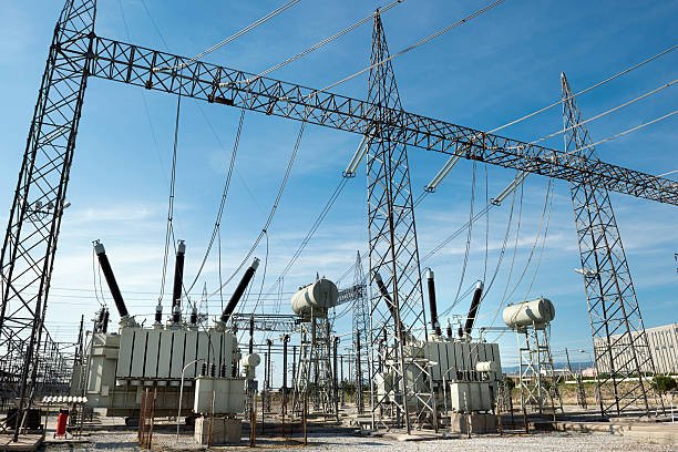
Choosing the wrong transformer configuration can increase equipment costs, waste installation space, reduce efficiency, or create unacceptable electrical safety risks. Buyers comparing conventional two-winding transformers with autotransformers may struggle to determine whether the simpler design is suitable for their voltage-conversion requirements. Understanding how an autotransformer works, where it performs best, and what limitations it introduces helps engineers and procurement teams make informed decisions about transformer selection.
An autotransformer is a transformer that uses a single continuous winding with one or more electrical taps shared by the input and output circuits to change voltage levels. Unlike a conventional two-winding transformer, it transfers energy through both electromagnetic induction and direct electrical conduction. Autotransformers are generally suitable when the input and output voltages are relatively close and electrical isolation between circuits is not required. Common applications include interconnecting power systems with similar voltage levels, motor starting, and voltage regulation.
Although autotransformers can offer advantages in size, cost, material usage, and efficiency, their shared winding means that the input and output circuits are not electrically isolated. Buyers must therefore assess voltage ratio, grounding arrangements, fault protection, insulation requirements, and applicable standards before deciding whether an autotransformer is appropriate for their project.
What Is an Autotransformer and How Does an Autotransformer Work?
Choosing the wrong transformer can increase equipment cost, waste installation space, and reduce electrical efficiency. In applications where the input and output voltages are relatively close, a conventional two-winding transformer may provide more isolation and copper than the system actually needs. An autotransformer offers an alternative, but its shared winding creates an important limitation: the input and output circuits are electrically connected rather than galvanically isolated. Understanding how an autotransformer works, where it performs well, and when it should not be used helps engineers and buyers make a safer, more economical selection.
An autotransformer is an electrical transformer that uses a single continuous winding with one or more taps to provide different input and output voltages. It works through electromagnetic induction and a shared winding section, with part of the power transferred conductively through the electrical connection and part transferred magnetically. Compared with a similarly rated two-winding transformer, an autotransformer can be smaller, lighter, and more efficient, particularly when the input and output voltages are close. However, it does not provide electrical isolation between its input and output circuits.
Autotransformers are widely used in voltage adjustment, motor starting, laboratory power supplies, and some power-distribution applications. Their benefits depend on voltage ratio, load requirements, fault conditions, and safety requirements. The following guide explains the construction, operating principle, advantages, limitations, and selection criteria from a practical engineering and manufacturing perspective.
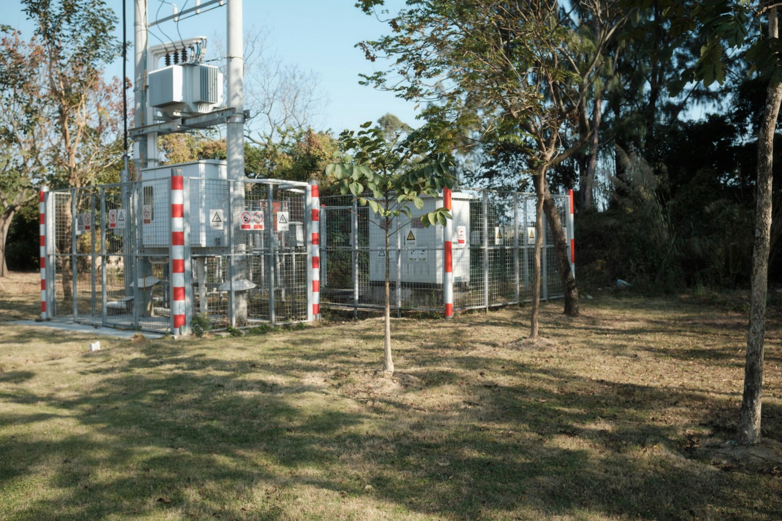
1. What Is an Autotransformer?
An autotransformer is a transformer that uses one winding for both the primary and secondary circuits. Instead of having two electrically separate windings, it uses a continuous winding with connections at selected points, known as taps.
A conventional two-winding transformer transfers power between separate primary and secondary windings through electromagnetic induction. An autotransformer also uses electromagnetic induction, but its winding arrangement creates a direct electrical connection between the input and output.
The winding generally contains two functional sections:
- Common winding: The section shared by the input and output circuits.
- Series winding: The section that contributes the voltage difference between the input and output terminals.
The exact winding sections carrying current depend on whether the autotransformer is configured for step-down or step-up operation.
An autotransformer provides galvanic isolation between its input and output circuits because both circuits use a common winding.False
The input and output circuits share an electrically continuous winding. An autotransformer therefore does not provide galvanic isolation; a separate isolation transformer is needed when electrical separation is required.
2. How Does an Autotransformer Work?
An autotransformer operates according to the same basic electromagnetic-induction principle as other transformers. When alternating voltage is applied to the winding, it creates alternating magnetic flux in the core. This flux induces voltage along the winding, with the voltage between taps determined by the number of turns between those connection points.
For an ideal autotransformer, voltage is proportional to the number of turns:
[\frac{V_H}{V_L}=\frac{N_H}{N_L}]
Where:
- (V_H) is the voltage across the higher-voltage winding section or terminals.
- (V_L) is the voltage across the lower-voltage section or terminals.
- (N_H) and (N_L) are the corresponding effective turn counts.
This relationship assumes the voltage quantities correspond to the stated winding sections. For three-phase units, line-to-line and phase-voltage conventions must be considered when comparing winding turns and terminal voltages.
Step-down operation
In a step-down autotransformer, the source is connected across the full winding, while the load is connected across a smaller section. The output voltage is therefore lower than the input voltage.
For example, an ideal autotransformer with a 240 V input and a 120 V output has a voltage ratio of 2:1. The load is connected across half the total effective turns, assuming a suitable winding and tap arrangement.
Step-up operation
In step-up operation, the source is connected across a smaller section of the winding and the load across a larger section. The output voltage is higher than the input voltage.
Both operating modes rely on the same principle: selecting different tap points changes the number of effective turns between the input and output terminals.
3. How Does an Autotransformer Transfer Power?
Power is transferred through two mechanisms: electromagnetic induction and direct electrical conduction through the common winding. This shared-winding arrangement is the key difference between an autotransformer and a conventional two-winding transformer.
For an ideal single-phase autotransformer:
[\S=V_H I_H=V_L I_L]
Where (S) is apparent power, (V_H) and (V_L) are the higher and lower terminal voltages, and (I_H) and (I_L) are their corresponding currents under the ideal power-balance assumption.
In an autotransformer, not all the power must be transferred magnetically through the core. A portion is transferred directly through the electrical connection, reducing the magnetic power handled by the transformer compared with a two-winding transformer of equivalent terminal ratings.
When the voltage ratio is close to 1:1, this can significantly reduce the required winding material and core capacity for a given input-output power rating.
4. What Are the Main Advantages of an Autotransformer?
Autotransformers are attractive when electrical isolation is not required and the voltage ratio is suitable.
| Feature | Autotransformer | Conventional two-winding transformer |
|---|---|---|
| Winding arrangement | One continuous winding with taps | Separate primary and secondary windings |
| Electrical isolation | No galvanic isolation | Galvanic isolation between windings |
| Copper requirement | Often lower for similar ratings and close voltage ratios | Generally higher for comparable ratings |
| Size and weight | Often smaller and lighter | Often larger and heavier |
| Efficiency | Can be higher because winding losses are reduced | Depends on design and rating |
| Voltage adjustment | Available through fixed taps or an adjustable mechanism | Available through fixed taps or an adjustable mechanism |
| Typical suitability | Voltage conversion, motor starting, voltage regulation where isolation is unnecessary | Applications requiring electrical isolation or independent winding circuits |
The actual size, efficiency, and cost advantage depends on the voltage ratio, rated power, insulation design, cooling method, and manufacturer construction. An autotransformer should not be assumed to be cheaper or more efficient in every application.
5. What Are the Limitations and Safety Considerations?
The most important limitation is the absence of galvanic isolation. Because the input and output share a winding, a fault or abnormal voltage condition on one side can be transferred electrically to the other side. The output must not automatically be treated as a safety-isolated or touch-safe supply.
Other considerations include:
- Fault current: Autotransformer impedance and the upstream supply determine available fault current. Protection must be coordinated with the system.
- Voltage compatibility: The selected taps and winding insulation must suit the intended input and output voltages.
- Overload capability: Winding current, temperature rise, and cooling limits must remain within the transformer's rating.
- Grounding and protection: Earthing, overcurrent protection, and enclosure requirements depend on the installation and applicable electrical codes.
- Harmonics and load type: Nonlinear loads and motor applications may affect heating and performance and should be considered during selection.
An autotransformer can always replace a conventional isolation transformer whenever the input and output voltage ratings are the same.False
Matching voltage ratings does not make the designs functionally equivalent. An autotransformer lacks galvanic isolation, so it is unsuitable where electrical separation is a safety or functional requirement.
6. Where Are Autotransformers Commonly Used?
Autotransformers are used in several applications where voltage conversion is needed without separate-winding isolation.
| Application | Typical purpose | Key selection consideration |
|---|---|---|
| Motor starting | Reduce voltage applied to a motor during startup | Starting torque, starting current, and duty cycle |
| Laboratory voltage adjustment | Provide variable AC output using an adjustable autotransformer | Output range, current rating, enclosure, and operator protection |
| Power-system interconnection | Connect systems with relatively close voltage levels | Voltage ratio, impedance, fault duty, and grounding arrangement |
| Voltage correction | Adjust voltage within an appropriate system design | Load variation, tap range, and voltage-control requirements |
| Industrial equipment | Adapt supply voltage for compatible machinery | Load characteristics, operating environment, and protection |
Adjustable autotransformers, sometimes called Variacs when referring to a specific style of variable transformer, are useful for controlled AC voltage adjustment. Their outputs are not inherently isolated from the supply and must be treated accordingly.
7. How Should Buyers Select an Autotransformer?
Before purchasing an autotransformer, confirm the electrical and operating requirements rather than choosing by voltage ratio alone.
Key checks include:
- Input and output voltage: Specify rated voltage, frequency, phase configuration, and required tap range.
- Rated capacity: Determine the required kVA rating using the load's voltage and current requirements, including starting or transient demands where applicable.
- Duty cycle: Identify continuous operation, intermittent use, motor-starting duty, and expected overload conditions.
- Impedance and fault requirements: Verify short-circuit current, protection coordination, and required short-circuit withstand capability.
- Isolation requirements: If the application requires galvanic isolation, select a suitable two-winding isolation transformer instead.
- Installation conditions: Consider ambient temperature, altitude, cooling, enclosure protection, noise, and mounting.
- Standards and testing: Confirm the project-required standards, routine tests, documentation, and acceptance criteria with the manufacturer.
The manufacturer should review the actual load and system conditions to ensure the autotransformer is suitable for the intended installation.
What Are the Main Advantages of an Autotransformer Compared With a Conventional Transformer?
Choosing between an autotransformer and a conventional two-winding transformer can significantly affect equipment cost, installation space, energy losses, and electrical safety. Selecting a conventional transformer when galvanic isolation is unnecessary may increase material use and overall cost. However, choosing an autotransformer where electrical isolation is essential can create serious safety and compliance problems. Understanding their structural differences helps engineers and buyers identify when an autotransformer offers genuine technical and economic advantages.
The main advantages of an autotransformer over a conventional two-winding transformer are lower material requirements, smaller size, lighter weight, potentially lower cost, and higher efficiency for comparable applications—particularly when the input and output voltages are relatively close. These benefits result from a single continuous winding shared by the input and output circuits. The main trade-off is that an autotransformer does not provide galvanic isolation, so a conventional isolation transformer is necessary when electrical separation is required.
For industrial facilities, motor-starting systems, voltage-regulation applications, and power networks, the best choice depends on voltage ratio, load characteristics, fault levels, installation requirements, and safety objectives. This article compares the major advantages of autotransformers and explains when those advantages justify selecting one over a conventional transformer.
1. Lower Copper Consumption and Material Requirements
One of the most important advantages of an autotransformer is its reduced winding material requirement.
A conventional transformer uses separate primary and secondary windings. An autotransformer uses a single continuous winding with taps, allowing part of the winding to be shared by both circuits. Depending on the voltage ratio and design, this arrangement can reduce the total conductor length and cross-sectional material required.
The savings are particularly significant when the input and output voltages are close. In that situation, a relatively large portion of the power can transfer conductively through the shared electrical connection rather than requiring all power to be transferred magnetically between separate windings.
For a comparable ideal single-phase application, let:
[\k=\frac{V_L}{V_H}]
where (V_L) is the lower voltage and (V_H) is the higher voltage, with (0\<k<1).
Under simplified assumptions, the autotransformer copper requirement relative to an equivalent two-winding transformer can be approximated by:
[\frac{W_{\mathrm{auto}}}{W_{\mathrm{two-winding}}}\
\approx 1-k]
This is a conceptual engineering relationship, not a guaranteed manufacturing ratio. Actual copper savings depend on current density, winding geometry, insulation clearances, cooling, impedance, and mechanical design.
For example, when the voltage ratio is close to 1:1, the theoretical material advantage can be substantial. As the voltage difference increases, the relative copper savings generally decrease.
2. Smaller Size and Lower Weight
Because an autotransformer can use less copper and may require less magnetic power-handling capacity for a given terminal rating, it can often be smaller and lighter than a conventional transformer serving a similar voltage-conversion duty.
This advantage is useful where equipment space is limited, transport costs are important, or the transformer must be integrated into a compact industrial system.
Potential benefits include:
- Reduced mounting-space requirements
- Lower transport and handling demands
- Easier integration into equipment cabinets or packaged systems
- Potential reductions in enclosure, support, and installation costs
However, size and weight are not determined by winding configuration alone. Insulation requirements, short-circuit withstand strength, cooling, and the specified impedance can significantly affect the final design. A high-voltage autotransformer may still require substantial insulation and mechanical construction.
3. Higher Efficiency and Lower Operating Losses
Autotransformers can achieve higher efficiency than comparable conventional transformers because their shared-winding design can reduce conductor material and winding resistance. Lower winding resistance can reduce copper losses, which increase with the square of current:
[\P_{\mathrm{cu}}=I^2R]
Here, (P_{\mathrm{cu}}) is winding copper loss, (I) is winding current, and (R) is winding resistance.
Both autotransformers and conventional transformers also experience core losses, including hysteresis and eddy-current losses. These losses depend on core material, flux density, frequency, and construction.
| Performance factor | Autotransformer | Conventional two-winding transformer |
|---|---|---|
| Winding arrangement | Shared winding | Separate primary and secondary windings |
| Copper requirement | Often lower for close voltage ratios | Often higher for comparable terminal ratings |
| Winding resistance losses | May be lower due to reduced conductor requirements | Depend on winding design and conductor size |
| Core losses | Depend on core design and operating conditions | Depend on core design and operating conditions |
| Overall efficiency | Often higher in suitable applications | Can also achieve very high efficiency with optimized design |
| Guaranteed performance | Must be verified from rated losses and efficiency data | Must be verified from rated losses and efficiency data |
Higher efficiency can reduce operating costs over the transformer's service life, particularly in continuously loaded applications. Buyers should compare manufacturer-guaranteed no-load and load losses at the required rating rather than assuming that every autotransformer will outperform every conventional transformer.
4. Lower Cost for Suitable Voltage Ratios
Reduced copper consumption, compact construction, and lower weight can translate into a lower purchase price for an autotransformer. Installation and transport costs may also be lower when its smaller footprint and mass simplify the project.
The economic advantage is usually strongest when the voltage ratio is close to 1:1 and galvanic isolation is not needed.
Nevertheless, total project cost should include more than the transformer purchase price. The buyer should also consider protective equipment, installation, maintenance, energy losses, and any additional safety measures required by the application.
An autotransformer is not automatically cheaper in every rating or design. A manufacturer should evaluate the complete specification before making a cost comparison.
5. Potentially Better Voltage Regulation
An autotransformer can offer favorable voltage regulation when its winding resistance and leakage reactance are low. Lower internal impedance generally reduces the voltage drop caused by load current, helping the output voltage remain closer to its intended value as loading increases.
Voltage regulation also depends on load power factor. A lagging power-factor load generally increases the reactive contribution to voltage drop, while a leading power-factor load can reduce the drop or produce a voltage rise.
This means the advantage must be evaluated under the expected load conditions. Percentage impedance, rated current, resistance-to-reactance ratio, and the operating power factor should all be considered.
For applications with strict voltage limits, buyers should request calculated or guaranteed voltage-regulation data at representative load levels instead of relying solely on the transformer type.
6. Useful Voltage Adjustment and Motor-Starting Applications
Autotransformers are widely used where a voltage conversion or adjustment is needed without electrical isolation.
Common applications include:
- Motor starting: An autotransformer starter applies reduced voltage during motor startup to limit inrush current. The reduced starting voltage also reduces starting torque, so the motor's load and acceleration requirements must be evaluated.
- Laboratory voltage adjustment: An adjustable autotransformer can provide a variable AC output for testing and equipment evaluation. Its output is not inherently isolated from the supply.
- Power-system voltage conversion: Autotransformers can connect voltage levels that are relatively close, provided insulation, grounding, protection, and system design requirements are satisfied.
- Industrial voltage adaptation: Suitable autotransformers can adapt supply voltages for compatible machinery and electrical systems.
The common winding makes these applications practical, but it also means that the output can remain electrically connected to the input supply. Appropriate safeguards and installation practices are essential.
7. What Are the Main Disadvantages Compared With a Conventional Transformer?
The advantages of an autotransformer must be weighed against its limitations. The most important is the lack of galvanic isolation between input and output.
| Consideration | Autotransformer | Conventional two-winding transformer |
|---|---|---|
| Galvanic isolation | Not provided | Provided between primary and secondary windings |
| Copper and size | Often lower for suitable voltage ratios | Often higher for comparable close-ratio duties |
| Efficiency | Often favorable in suitable applications | Depends on design and operating point |
| Fault transfer | Input-side electrical disturbances can be transferred through the shared connection | Separate windings provide electrical separation, though magnetic coupling still transfers energy and transients |
| Safety-sensitive supplies | Unsuitable where isolation is required | Often the appropriate choice when designed for the required isolation level |
| Parallel operation | Requires careful voltage-ratio, phase, and impedance compatibility | Also requires compatible voltage ratios, phase relationships, and impedances |
An autotransformer should not be selected where the application requires isolation for personnel protection, equipment design, or electrical-system functionality. In such cases, a properly specified conventional isolation transformer is generally more appropriate.
8. How Should Buyers Decide Which Transformer Type to Choose?
The selection process should begin with the electrical requirements rather than the anticipated material savings.
Choose an autotransformer when:
- Input and output voltages are relatively close.
- Electrical isolation is not required.
- Reduced size, weight, or material consumption is valuable.
- Voltage regulation and fault-current requirements can be met.
- The manufacturer can confirm compliance with applicable standards and project specifications.
Choose a conventional two-winding transformer when:
- Galvanic isolation is required.
- The input and output circuits must remain electrically separate.
- The system's grounding or protection arrangement requires separate windings.
- The application specification explicitly requires an isolation transformer.
In either case, confirm rated capacity, voltage ratio, frequency, impedance, temperature rise, insulation requirements, losses, cooling, enclosure, and short-circuit withstand capability before ordering.
What Are the Limitations and Safety Risks of Using an Autotransformer?
Autotransformers can reduce equipment size, material use, and operating losses, but their shared-winding design introduces important limitations that buyers and engineers must understand before installation. The most significant risk is that an autotransformer does not provide galvanic isolation between its input and output. A fault, wiring error, or unexpected supply voltage can therefore create hazardous conditions on the output side. In addition, incorrect impedance selection, inadequate overcurrent protection, or unsuitable load conditions can lead to overheating, equipment damage, and unsafe operation.
The main limitations of an autotransformer are the absence of galvanic isolation, potential transfer of electrical faults between input and output, sensitivity to incorrect wiring and grounding, and the need for appropriate overload and short-circuit protection. Autotransformers can also be unsuitable where strict isolation, specific grounding arrangements, or substantial voltage conversion is required. Safe use depends on correct ratings, suitable protection, proper installation, and compliance with applicable electrical standards.
For electrical engineers, industrial operators, and equipment buyers, understanding these limitations is essential when deciding whether an autotransformer is appropriate. The following guide explains the principal safety risks, operating constraints, and practical precautions that help ensure reliable service.
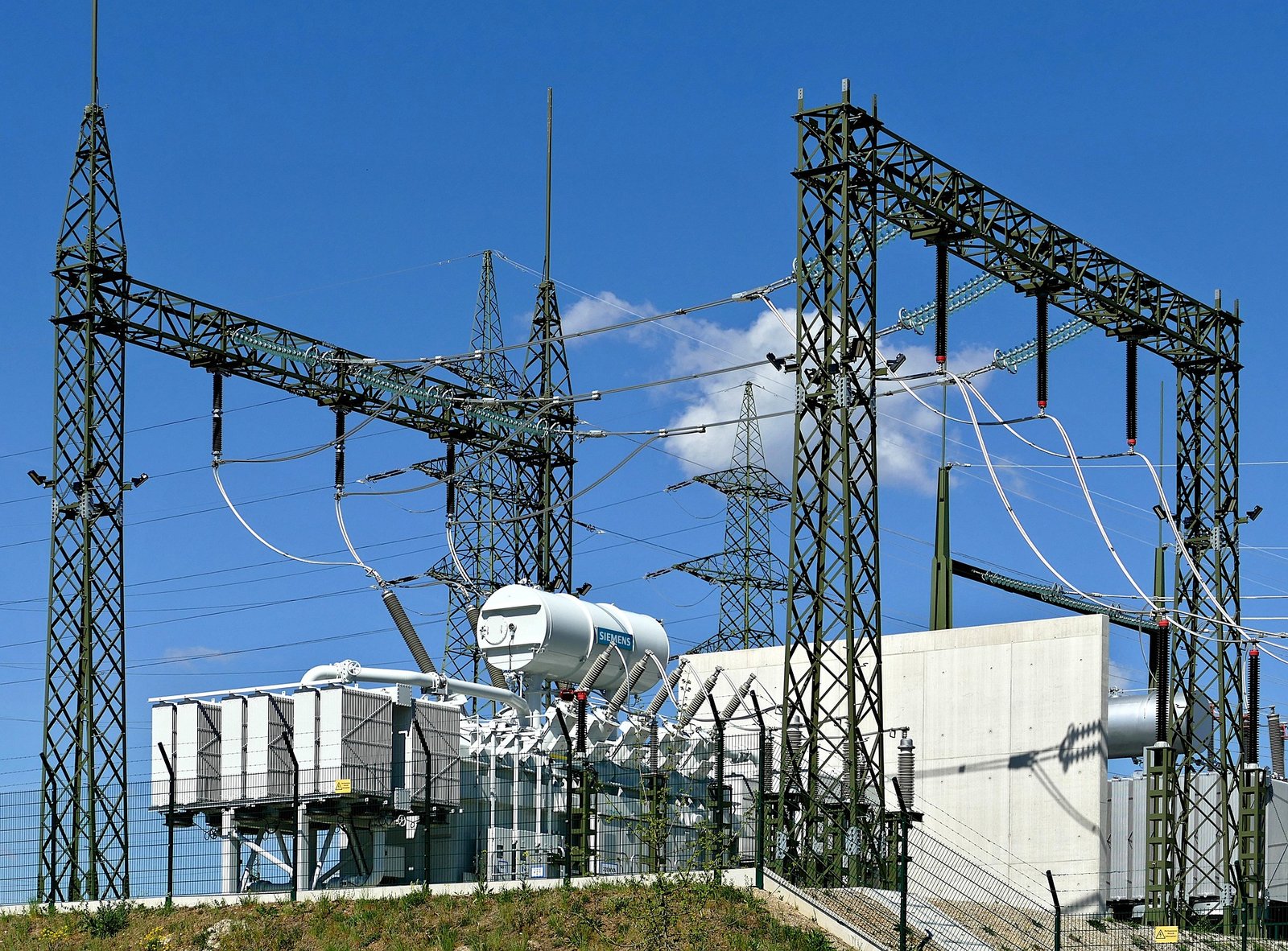
1. Lack of Galvanic Isolation
The most important limitation of an autotransformer is that its primary and secondary circuits share an electrically continuous winding. Unlike a conventional two-winding isolation transformer, an autotransformer does not electrically separate the input from the output.
This means the output cannot automatically be considered isolated, touch-safe, or suitable for circuits that require galvanic separation. Depending on the connection and grounding arrangement, a hazardous voltage relative to earth may be present at output terminals even when the output voltage is lower than the supply voltage.
This limitation matters in laboratory testing, maintenance work, electronic equipment servicing, medical applications, and other situations where electrical isolation is required by the design or applicable standards.
An autotransformer provides galvanic isolation because its input and output use separate electrical windings.False
An autotransformer uses a shared, continuous winding. It provides voltage transformation but not galvanic isolation between input and output.
Practical safety precautions
- Use a properly rated isolation transformer when electrical separation is required.
- Never assume that a reduced output voltage is safe to touch.
- Identify input, output, common, and tapped terminals clearly.
- Apply appropriate guarding, grounding, and protective measures for the actual installation.
- Follow approved isolation, lockout/tagout, and verification procedures before maintenance.
2. Electrical Faults Can Affect Both Input and Output
Because the input and output share a winding, an electrical fault or incorrect connection can affect both sides of the autotransformer. The exact hazard depends on the winding arrangement, system grounding, fault location, and connected equipment.
A fault on the supply side may expose the output circuit to a dangerous potential. Similarly, a wiring error or insulation failure can create abnormal currents and voltages that damage the transformer or connected loads.
Autotransformers also do not eliminate the need for a short-circuit study. Their impedance helps limit fault current, but the actual available current depends on the upstream source, feeder cables, fault location, and other network impedances.
| Potential problem | Possible consequence | Recommended precaution |
|---|---|---|
| Input-to-output fault transfer | Hazardous voltage on the output circuit | Evaluate the complete grounding and protection arrangement |
| Incorrect terminal connections | Short circuit, excessive current, or equipment damage | Follow the manufacturer's connection diagram |
| Winding insulation failure | Arcing, overheating, or loss of safe operation | Specify appropriate insulation and verify test documentation |
| Excessive short-circuit current | High thermal and mechanical stress | Perform fault-current calculations and verify protective-device ratings |
| Incorrect grounding | Unexpected touch voltage or ineffective fault clearing | Design and inspect grounding in accordance with applicable requirements |
Protective devices must be selected to address both the maximum prospective fault current and the minimum fault current that must be detected reliably. A qualified engineer should verify that the protection system can clear faults under the actual operating conditions.
3. Overloading and Overheating Risks
An autotransformer must be operated within its rated capacity, winding-current limits, temperature-rise limits, and specified duty cycle. Although its construction can reduce material requirements, it is not immune to overheating.
Excessive load current increases winding copper losses, which rise approximately with the square of current:
[\P_{\mathrm{cu}}=I^2R]
Here, (P_{\mathrm{cu}}) is winding copper loss, (I) is winding current, and (R) is winding resistance.
If current exceeds the rated value for too long, winding temperature can rise beyond the design limit. Prolonged overheating accelerates insulation aging and may eventually cause winding failure.
Autotransformers used for motor starting require particular attention. They may carry high current during a starting interval, so the allowable duty cycle, starting frequency, cooling arrangement, and motor acceleration time must match the manufacturer's rating.
Common warning signs
- Unusual temperature rise
- Burning odor or visible discoloration
- Abnormal buzzing, vibration, or arcing
- Repeated operation of protective devices
- Unexpected output-voltage changes
- Damaged terminals, cables, or insulation
If these signs occur, the equipment should be assessed by qualified personnel before being returned to service.
4. Grounding and Overcurrent Protection Requirements
Autotransformer safety depends on how it is connected to the electrical system. Because the winding is shared, grounding and protective-device arrangements must be designed for the actual circuit rather than copied from a conventional isolated secondary circuit.
Protection may need to address overload, short circuit, earth fault, winding temperature, and abnormal operating conditions. The appropriate devices and settings depend on the system voltage, transformer configuration, available fault current, connected load, and applicable electrical codes.
| Safety measure | Purpose | Buyer or engineer check |
|---|---|---|
| Overcurrent protection | Limits damage from overloads and short circuits | Verify device ratings and coordination |
| Grounding and bonding | Provides a defined protective path where required | Confirm the intended system grounding arrangement |
| Thermal protection | Detects excessive temperature where specified | Check sensors, alarms, trips, and operating limits |
| Enclosure and terminal protection | Reduces accidental contact and environmental exposure | Verify enclosure rating and installation location |
| Clear terminal identification | Prevents connection errors | Check labels, wiring diagrams, and commissioning records |
| Maintenance isolation | Helps protect workers during servicing | Follow approved isolation and verification procedures |
Grounding does not create galvanic isolation. A correctly grounded autotransformer still has an electrical connection between input and output.
5. Limited Suitability for Some Voltage Ratios and Applications
Autotransformers are often most attractive when input and output voltages are relatively close. As the voltage ratio moves farther from 1:1, the relative material and cost advantage generally decreases, although the actual result depends on the design and rating.
Other applications may require a conventional transformer because the input and output circuits must be electrically separated. These can include equipment with specific isolation requirements, certain grounding arrangements, and installations where the project standard explicitly calls for a two-winding transformer.
Autotransformer selection must also account for voltage variation, load power factor, impedance, short-circuit withstand capability, insulation requirements, cooling, and duty cycle. The transformer should not be selected by voltage ratio alone.
6. Voltage Regulation and Equipment Compatibility
An autotransformer has internal impedance, so its output voltage changes with load current and power factor. A design with low impedance may offer favorable voltage regulation, but it can also permit higher short-circuit current. A higher-impedance design can limit fault current more effectively while producing greater load-related voltage drop.
This trade-off is important for motor drives, industrial controls, laboratory equipment, and sensitive electronic loads. Engineers should calculate expected voltage variation under representative load conditions and verify that the output remains within the connected equipment's permissible range.
For motor-starting applications, reduced starting voltage also reduces starting torque. The motor and driven load must therefore be capable of accelerating successfully at the selected voltage.
7. How Can Buyers Reduce Autotransformer Safety Risks?
A structured selection and verification process can prevent many problems before the equipment reaches the installation site.
Before purchasing, buyers should:
- Define the electrical application: Specify input and output voltages, frequency, phase configuration, kVA rating, load type, and duty cycle.
- Confirm isolation requirements: Use a conventional isolation transformer if galvanic isolation is necessary.
- Review impedance and fault levels: Check available short-circuit current, protective-device ratings, and coordination.
- Verify ratings and insulation: Confirm winding-current limits, temperature rise, cooling, enclosure, and environmental requirements.
- Review manufacturer documentation: Check nameplate information, connection diagrams, guaranteed impedance, and required test reports.
- Plan safe commissioning: Ensure that installation, grounding, protection, testing, and operating procedures are reviewed by qualified personnel.
- Establish maintenance requirements: Define inspection intervals and the response to overheating, abnormal noise, damaged insulation, or repeated protective trips.
The manufacturer should receive enough information about the electrical system to assess the application, not just the requested voltage ratio.
When Should You Use an Autotransformer in Power Systems and Industrial Applications?
Selecting the wrong transformer can increase equipment costs, waste installation space, and compromise electrical safety. In industrial facilities and power networks, a conventional two-winding transformer may be unnecessarily large when the input and output voltages are relatively close. An autotransformer can provide a more compact, economical solution, but its shared winding introduces an important limitation: it does not provide galvanic isolation. Understanding when to use an autotransformer—and when to choose a conventional transformer instead—helps engineers and buyers balance efficiency, performance, and safety.
An autotransformer is suitable when input and output voltages are compatible with a shared-winding design, electrical isolation is not required, and reduced material use, size, weight, or operating losses are valuable. Common applications include industrial motor starting, adjustable AC voltage supplies, voltage adaptation, and power-system interconnections between relatively close voltage levels. Its suitability must be verified against load requirements, voltage regulation, fault current, grounding, and applicable safety standards.
The best application depends on the electrical system rather than the transformer type alone. The following guide explains the most suitable use cases, their advantages, and the technical checks needed before purchasing or installing an autotransformer.
1. When Is an Autotransformer the Best Choice?
An autotransformer uses one continuous winding with taps, so a portion of the winding is shared between the input and output circuits. Unlike a conventional two-winding transformer, it does not electrically separate the primary and secondary circuits.
This design can reduce conductor requirements and the amount of power that must be transferred magnetically through the core. The advantages are often greatest when the input and output voltages are relatively close.
An autotransformer is worth considering when:
- The required voltage conversion suits a shared-winding arrangement.
- Galvanic isolation is not a requirement.
- Reduced equipment size and weight are important.
- Lower material consumption and lifecycle costs are desirable.
- The design can meet voltage-regulation, thermal, and short-circuit requirements.
An autotransformer is always preferable to a conventional transformer when the input and output voltages are close.False
A close voltage ratio can improve the autotransformer's material and cost advantages, but the lack of galvanic isolation and the system's grounding, protection, and insulation requirements may make a conventional transformer necessary.
2. Industrial Motor Starting
One of the most established applications of autotransformers is reduced-voltage starting for large induction motors.
When a motor starts, it may draw several times its rated current. This can cause supply-voltage dips, disturb other equipment, and increase electrical and mechanical stress. An autotransformer starter applies a reduced voltage during startup, then transitions the motor to its normal supply arrangement.
Potential benefits include:
- Reduced supply current compared with direct-on-line starting.
- Lower voltage disturbances in the facility's electrical network.
- Suitable starting torque for certain high-power motor applications.
- Compact, economical starting equipment for appropriate motor duties.
However, reducing motor voltage also reduces starting torque. For an induction motor under typical starting conditions, torque is approximately proportional to the square of applied voltage.
For example, if the motor receives 80% of rated voltage, the approximate starting torque is:
[\T_{\text{start}}\approx(0.8)^2T_{\text{DOL}}=0.64T_{\text{DOL}}]
This is an illustrative approximation; actual starting performance depends on the motor design, starter connection, and driven load.
Autotransformer starters are therefore useful for compatible pumps, fans, compressors, and other industrial machines, provided that starting torque, acceleration time, duty cycle, and thermal limits are verified.
3. Power-System Voltage Conversion
Autotransformers are often considered for interconnecting power-system voltage levels that are relatively close. Their shared winding can reduce copper requirements, equipment weight, and installation footprint compared with a conventional transformer of comparable terminal rating.
They may be suitable for transmission or subtransmission applications where the system design does not require galvanic isolation between the connected voltage levels.
Before selecting an autotransformer for a power network, engineers should evaluate:
- Rated voltage and capacity.
- Voltage regulation under changing loads.
- Transformer impedance and prospective short-circuit current.
- System grounding and earth-fault protection.
- Insulation coordination and transient overvoltage requirements.
- Network stability and protection coordination.
An autotransformer is not automatically appropriate simply because the voltage levels are close. A conventional transformer may be necessary if the connected systems require electrical separation or different grounding arrangements.
4. Adjustable AC Voltage and Industrial Testing
Adjustable autotransformers are useful when a controlled AC voltage is needed for testing or equipment evaluation. A movable tap or brush changes the effective number of turns connected to the output, allowing the output voltage to be varied over the specified range.
Typical applications include:
- Laboratory testing of compatible AC equipment.
- Controlled energization during maintenance or troubleshooting.
- Industrial equipment voltage adaptation.
- Electrical product testing where an adjustable supply is required.
The output current remains limited by the equipment's rating, and voltage adjustment does not provide isolation.
Safety note: An adjustable autotransformer must not be treated as an isolation transformer. Its output can remain electrically connected to the supply and may present a hazardous voltage relative to earth. Use an appropriately rated isolation transformer when electrical separation is required.
5. Voltage Adaptation and Regulation
Autotransformers can adapt voltage for compatible equipment or installations when the supply voltage differs from the required operating voltage. Depending on the design, voltage selection may use fixed taps or an adjustable mechanism.
Their performance depends on internal impedance, load current, and power factor. Lower impedance generally reduces load-related voltage drop but can permit higher short-circuit current. Higher impedance generally limits fault current while increasing the voltage drop under load.
| Application requirement | Potential benefit of an autotransformer | Key engineering check |
|---|---|---|
| Close input and output voltage levels | Reduced material use and compact construction | Voltage ratio and insulation requirements |
| Large motor starting | Reduced-voltage starting and lower supply current | Starting torque, acceleration time, and duty cycle |
| Adjustable AC testing | Flexible voltage control | Output current rating and isolation requirements |
| Power-system interconnection | Potential savings in size and materials | Fault levels, grounding, and network protection |
| Industrial voltage adaptation | Economical voltage conversion | Load profile, regulation, and permissible voltage range |
For sensitive loads, engineers should calculate expected voltage variation at representative load levels and confirm that the output remains within the connected equipment's permitted operating range.
6. When Should You Choose a Conventional Transformer Instead?
A conventional two-winding transformer is generally preferable when electrical isolation is required or when the input and output circuits must remain electrically separate.
| Consideration | Autotransformer | Conventional two-winding transformer |
|---|---|---|
| Winding arrangement | One shared, continuous winding | Separate primary and secondary windings |
| Galvanic isolation | Not provided | Provided between windings |
| Material use for close voltage ratios | Often lower | Often higher for comparable terminal ratings |
| Size and weight | Often lower | May be greater |
| Safety-sensitive isolated supply | Unsuitable when isolation is required | Often appropriate when correctly specified |
| Power-system applications | Suitable when grounding and protection permit | Suitable when separate windings are required |
Autotransformers also need appropriate overcurrent protection, grounding, insulation, and short-circuit withstand capability. Their compact construction does not remove the need for a complete electrical safety assessment.
7. What Should Buyers Verify Before Ordering?
A practical purchasing review should confirm the application and its electrical constraints before a transformer is manufactured.
- Input and output ratings: Specify voltages, frequency, phase configuration, and required tap range.
- Rated capacity: Determine the required kVA rating from load voltage and current, including starting or transient demands.
- Load characteristics: Identify continuous loading, motor-starting duty, harmonics, and expected overload conditions.
- Impedance and fault current: Check voltage regulation, available short-circuit current, and protective-device coordination.
- Isolation requirements: Confirm that the application does not require galvanic isolation.
- Installation conditions: Review cooling, ambient temperature, enclosure, altitude, and mounting requirements.
- Test documentation: Specify the applicable standards, routine tests, guaranteed impedance, and acceptance criteria.
For motor-starting projects, provide motor power, starting current, required torque, acceleration time, and starting frequency. For power-system projects, provide the upstream fault level, grounding arrangement, and relevant network data.
How Do You Choose Between an Autotransformer and a Two-Winding Transformer?
Choosing between an autotransformer and a conventional two-winding transformer affects more than purchase price. The decision influences electrical safety, energy efficiency, equipment size, voltage regulation, fault protection, and long-term operating costs. An autotransformer can offer substantial material and efficiency advantages when input and output voltages are relatively close, but its shared winding does not provide galvanic isolation. Selecting it without checking the system's isolation and grounding requirements can create serious safety and compliance problems.
Choose an autotransformer when the input and output voltages are relatively close, galvanic isolation is not required, and compact size, reduced material use, or higher efficiency are priorities. Choose a two-winding transformer when electrical isolation is necessary, the input and output circuits must remain electrically separate, or the application's grounding and safety requirements call for separate windings. In either case, verify rated capacity, voltage ratio, impedance, fault-current levels, load characteristics, and applicable standards before purchasing.
For engineers, facility managers, and transformer buyers, the best choice depends on the actual electrical application rather than the transformer type alone. This guide compares both designs and explains how to evaluate their technical, safety, and economic trade-offs.

1. Understand the Fundamental Difference
The most important difference is the winding arrangement.
An autotransformer uses one continuous winding with taps. Part of the winding is shared between the input and output circuits, allowing power to transfer through both direct electrical conduction and electromagnetic induction.
A two-winding transformer has separate primary and secondary windings. Energy transfers magnetically through the core, while the windings remain electrically separate unless another connection is intentionally introduced externally.
This distinction determines whether galvanic isolation is available and influences the amount of copper, the transformer size, and the design's cost and efficiency.
An autotransformer provides galvanic isolation between its input and output because it uses electromagnetic induction.False
Although electromagnetic induction occurs, the input and output share an electrically continuous winding. A conventional two-winding transformer provides galvanic isolation between its primary and secondary windings when designed and installed appropriately.
2. Compare Cost, Size, Weight, and Efficiency
Autotransformers can be smaller and lighter because their shared winding reduces the amount of conductor material required for many voltage-conversion applications. They can also have lower winding losses and higher efficiency than a comparable two-winding design, particularly when the voltage ratio is close to 1:1.
The size of the advantage depends on the voltage ratio, rated capacity, impedance requirements, insulation design, and cooling arrangement. A conventional transformer may be the more economical overall solution when isolation is required or when a specialized two-winding design better suits the application.
| Selection factor | Autotransformer | Two-winding transformer |
|---|---|---|
| Winding arrangement | One shared, continuous winding | Separate primary and secondary windings |
| Galvanic isolation | Not provided | Provided between windings |
| Copper requirement | Often lower for close voltage ratios | Often higher for comparable terminal ratings |
| Size and weight | Often smaller and lighter | Often larger and heavier |
| Efficiency | Often higher in suitable applications | Can also achieve very high efficiency |
| Initial cost | Often lower when isolation is unnecessary | May cost more, depending on design |
| Safety-related separation | Unsuitable where isolation is required | Often appropriate when correctly specified |
Buyers should compare guaranteed losses, rated performance, installation costs, and lifecycle costs rather than assuming one design is always more efficient or less expensive.
3. Evaluate the Voltage Ratio
The voltage ratio is a major factor in deciding whether an autotransformer offers meaningful advantages.
When input and output voltages are close, a relatively large part of the power can transfer conductively through the shared winding. This reduces the portion of power that must be transferred magnetically and can reduce material requirements.
For example, a system that converts 240 V to 220 V may be a candidate for an autotransformer if isolation is unnecessary and the equipment ratings permit that arrangement. A system converting between substantially different voltage levels may offer less material savings, although the actual outcome depends on the design.
The decision should also account for voltage regulation, load current, and insulation requirements. A suitable ratio alone does not establish that an autotransformer is safe or appropriate.
4. Decide Whether Electrical Isolation Is Required
Electrical isolation is often the deciding factor.
A two-winding transformer is generally preferred when the application requires electrical separation between the input and output circuits. This may be important for personnel protection, equipment design, grounding arrangements, or compliance with a specific project standard.
An autotransformer does not provide this separation. A reduced output voltage should not automatically be considered safe to touch, and the output may remain at a hazardous potential relative to earth depending on the connection and grounding arrangement.
| Application requirement | Generally preferred option | Reason |
|---|---|---|
| Voltage conversion without an isolation requirement | Autotransformer may be suitable | Compact, economical shared-winding design |
| Galvanic isolation for equipment or safety | Two-winding transformer | Separate input and output windings |
| Adjustable AC voltage for compatible testing | Adjustable autotransformer, if isolation is unnecessary | Convenient voltage adjustment |
| Industrial motor starting | Autotransformer starter or another suitable starting method | Can reduce motor starting current |
| Sensitive equipment requiring an isolated supply | Suitable isolation transformer | Provides electrical separation when properly specified |
| Power-system interconnection | Either type, based on system study | Depends on voltage ratio, grounding, fault duty, and insulation requirements |
The final decision should follow the application's safety requirements and applicable electrical standards.
5. Consider Impedance, Voltage Regulation, and Fault Current
Both transformer types have internal impedance, which affects voltage drop under load and limits short-circuit current.
Higher impedance generally reduces fault current but increases load-related voltage drop. Lower impedance generally improves voltage regulation but permits higher prospective fault current. The correct balance depends on load characteristics, upstream source impedance, protective devices, and the required short-circuit withstand capability.
For parallel operation, engineers must also verify compatible voltage ratios, phase relationships, polarity, percentage impedance, and impedance angles. An autotransformer cannot be assumed to share load correctly with a two-winding transformer merely because their nominal voltages are similar.
Before purchasing, request the manufacturer's guaranteed percentage impedance and test documentation, and have the system's fault-current and protection requirements evaluated.
6. Match the Transformer to the Application
The following examples illustrate how application requirements guide the choice.
Industrial motor starting
An autotransformer starter can reduce the voltage applied to a large induction motor during startup, helping limit supply current and voltage dips. However, lower starting voltage also reduces starting torque. Motor torque requirements, acceleration time, and starting frequency must be checked.
Distribution and voltage adaptation
An autotransformer may be suitable for connecting relatively close voltage levels where electrical isolation is unnecessary. The system engineer must confirm grounding compatibility, insulation coordination, fault levels, and protection.
Laboratory and equipment testing
An adjustable autotransformer can provide a variable AC voltage for testing compatible equipment. If electrical separation is required, use an appropriate isolation transformer instead.
Sensitive or isolation-dependent equipment
A two-winding transformer is generally the preferred option when the equipment or safety design requires galvanic isolation. The required isolation level, insulation system, and protective arrangements must still be specified correctly.
7. Use a Practical Selection Checklist
Before requesting a quotation, buyers should define the following parameters:
- Rated capacity in kVA or MVA
- Primary and secondary voltages
- Frequency and phase configuration
- Required voltage regulation and permitted variation
- Load profile, power factor, and starting current
- Available short-circuit current and protective-device ratings
- Isolation and grounding requirements
- Parallel-operation or future-expansion plans
- Cooling, enclosure, ambient temperature, and installation conditions
- Applicable standards, testing, and documentation requirements
Ask the manufacturer to evaluate the proposed transformer against these conditions. If the choice involves safety-sensitive equipment, unusual grounding arrangements, or significant fault-current constraints, obtain a formal engineering review before finalizing the design.
What Technical Specifications Should Buyers Check Before Selecting an Autotransformer?
Selecting an autotransformer based on voltage and kVA alone can lead to costly problems after installation. An incorrectly specified unit may overheat under actual loading, deliver unacceptable voltage regulation, exceed available fault-current limits, or fail to meet the system’s insulation and grounding requirements. These risks are especially important in industrial facilities, motor-starting systems, and power networks where equipment must operate reliably under changing load conditions.
Before selecting an autotransformer, buyers should verify its rated capacity (kVA), input and output voltages, frequency, phase configuration, rated current, percentage impedance, voltage regulation, insulation level, temperature-rise limits, cooling method, tap range, duty cycle, short-circuit withstand capability, protection requirements, and applicable standards. They must also confirm that galvanic isolation is not required, because an autotransformer’s input and output share an electrically continuous winding.
The best purchasing process combines electrical calculations, application-specific requirements, manufacturer data, and documented testing. The following checklist explains which specifications matter, why they matter, and what buyers should request before approving a quotation.
1. Confirm Rated Capacity and Load Requirements
The autotransformer’s rated capacity must accommodate the actual load, not simply the equipment’s nominal label. Buyers should establish continuous demand, peak loading, starting current, operating duration, ambient conditions, and expected future expansion.
The shared winding changes the relationship between the transformer’s total input/output power and the amount of power transferred magnetically. Consequently, the winding design and permissible current must be checked using the manufacturer’s ratings rather than assuming that every autotransformer can deliver the same output capacity as a conventional transformer of identical physical size.
For motor-starting applications, specify the motor’s rated power, full-load current, locked-rotor current, required starting torque, acceleration time, and expected number of starts per hour. For continuous industrial service, confirm the load profile and any overload requirements.
| Specification | What buyers should verify | Why it matters |
|---|---|---|
| Rated capacity | kVA or MVA at specified operating conditions | Prevents overloading |
| Continuous load | Expected operating kVA and current | Establishes normal thermal duty |
| Peak load | Maximum demand and duration | Helps assess short-term thermal stress |
| Starting duty | Starting current, torque, and duration | Critical for motors and other high-inrush loads |
| Future capacity | Planned load growth | Reduces the risk of premature replacement |
Do not add an arbitrary oversizing percentage without checking the load profile, harmonics, ambient temperature, and manufacturer guidance.
2. Verify Input Voltage, Output Voltage, and Frequency
The primary and secondary voltage ratings must match the electrical system. Confirm whether each voltage is a line-to-line or line-to-neutral value, particularly in three-phase applications.
Buyers should also identify the required operating voltage range, allowable output variation, supply-voltage fluctuations, and any need for voltage adjustment under load. The selected turns ratio and tap arrangement must support the intended operating conditions.
Frequency is equally important. A transformer designed for one frequency cannot automatically be assumed suitable for a lower frequency at the same voltage. Lower frequency increases magnetic flux density if voltage and winding turns remain unchanged, potentially causing excessive magnetizing current, saturation, and overheating.
For three-phase equipment, specify the system voltage, phase sequence, connection arrangement, and grounding method. Confirm that the proposed autotransformer is designed for the actual network configuration.
3. Check Rated Current and Percentage Impedance
Rated current is necessary for selecting conductors, terminals, busbars, disconnects, and protective devices. For a single-phase transformer:
[\I=\frac{S}{V}]
For a balanced three-phase system:
[\I=\frac{S}{\sqrt{3}V_{LL}}]
where (S) is apparent power and (V_{LL}) is line-to-line voltage. Use consistent units and the manufacturer's specified winding and terminal ratings.
Percentage impedance, or %Z, is another essential specification. It affects voltage drop under load and the prospective short-circuit current. In a simplified transformer-terminal estimate, assuming the upstream source impedance is negligible:
[\I_{SC}\approx I_{\text{rated}}\frac{100}{%Z}]
This is an approximation, not a complete system fault calculation. Actual fault current depends on upstream source impedance, cables, fault location, and other connected sources.
A higher transformer percentage impedance generally reduces prospective short-circuit current at the transformer terminals, all else being equal.True
Transformer impedance limits fault current. The actual fault level also depends on upstream source impedance and the rest of the electrical network.
Request the specified impedance value, applicable tolerance, test conditions, and test report. Confirm that the resulting fault current is compatible with the interrupting ratings of breakers and fuses and with the withstand ratings of downstream equipment.
4. Evaluate Voltage Regulation and Tap Range
Voltage regulation describes how the output voltage changes between specified no-load and loaded conditions. Poor regulation can affect motor performance, control equipment, lighting, and sensitive industrial loads.
Buyers should request guaranteed voltage-regulation data at the relevant load and power factor, as well as the expected impedance voltage drop. Where the supply voltage varies, determine whether fixed taps, off-circuit taps, or an appropriate adjustable arrangement can maintain the required output voltage.
| Requirement | Specification to review |
|---|---|
| Stable output voltage | Guaranteed regulation or voltage-drop data |
| Variable incoming supply | Input operating range and tap settings |
| Routine voltage adjustment | Tap range and adjustment increments |
| Adjustment while energized | Explicit confirmation that the tap-changing device is designed for that operation |
| Motor-starting voltage | Starting-voltage setting and expected torque performance |
Never assume that a tap changer can be operated under load. Many tap arrangements require the transformer to be de-energized before adjustment. Follow the manufacturer's operating instructions.
5. Confirm Insulation, Temperature Rise, and Cooling
The insulation system must be suitable for the maximum operating voltage, transient exposure, environmental conditions, and applicable electrical standards. Because an autotransformer does not provide galvanic isolation, its insulation ratings do not remove the need to evaluate grounding and personnel-protection requirements.
Specify the required insulation level and withstand tests, including the applicable power-frequency and impulse requirements where relevant. Also verify clearances, creepage distances, winding insulation materials, and environmental protection.
Temperature rise and cooling determine whether the autotransformer can operate reliably at its rated load. Request the rated ambient temperature, permitted temperature rise, insulation thermal class, cooling designation, and any required derating for altitude, enclosure, dust, or restricted ventilation.
For oil-immersed units, verify the insulating-liquid type, containment requirements, leak protection, and fire-safety provisions. For dry-type units, check the enclosure rating, ventilation, contamination exposure, and suitability for the installation environment.
6. Specify Duty Cycle, Harmonics, and Environmental Conditions
An autotransformer used for intermittent motor starting may require a different thermal design from one intended for continuous voltage conversion. Provide the manufacturer with the actual duty cycle, including the duration and frequency of high-current events.
Nonlinear loads, such as variable-frequency drives and rectifiers, may introduce harmonic currents and additional heating. If these loads are present, disclose their characteristics and ask the manufacturer to confirm whether derating or a specialized design is required.
Environmental conditions should also be explicit. Include ambient temperature, altitude, indoor or outdoor location, humidity, dust, corrosive atmosphere, vibration, enclosure requirements, and any seismic or noise limits specified by the project.
These details help the manufacturer select appropriate insulation, cooling, terminals, enclosure construction, and protection features.
7. Review Protection, Grounding, and Safety Requirements
The protection design must match the autotransformer’s current ratings, impedance, application, and available fault current. Depending on the installation, requirements may include overcurrent protection, thermal protection, temperature monitoring, surge protection, and appropriate isolation and disconnecting devices.
Grounding must be assessed for the complete electrical system, including neutral arrangements, earth-fault protection, and the potential voltage of output conductors relative to earth. Since the windings are electrically connected, an autotransformer must not be treated as an isolation transformer.
Buyers should request connection diagrams and confirm that the intended system can safely accommodate the shared-winding design. If the application requires galvanic isolation, select a suitable two-winding transformer instead.
8. Verify Standards, Factory Tests, and Documentation
Before issuing a purchase order, confirm the standards applicable to the installation, equipment type, and jurisdiction. Depending on the project, these may include relevant IEC or IEEE requirements and local electrical codes.
Request a clear technical datasheet and a list of guaranteed values. The purchase specification should identify the rated capacity, voltage ratio, frequency, phase, impedance, insulation level, cooling method, temperature-rise limits, tap arrangement, enclosure, and accessories.
Factory acceptance documentation may include routine electrical tests, winding-resistance measurements, turns-ratio verification, polarity or phase-relation checks, insulation tests, and applicable dielectric tests. Additional tests should be agreed upon where the application warrants them.
Do not rely on a generic certificate alone. Verify that the offered model, ratings, and test documents correspond to the actual unit being supplied.
Autotransformer Buyer Checklist
Before approving the final quotation, confirm that you have:
- Defined the load, rated capacity, and duty cycle.
- Verified input/output voltage, frequency, phase, and connection arrangement.
- Checked rated current, percentage impedance, and fault-current compatibility.
- Confirmed voltage regulation, tap range, and adjustment method.
- Specified insulation, cooling, temperature-rise, and environmental requirements.
- Disclosed motor-starting duty and nonlinear loads.
- Reviewed grounding, protection, and isolation requirements.
- Confirmed applicable standards, guaranteed performance, factory tests, and documentation.
Conclusion
An autotransformer is a practical voltage-conversion solution when the input and output voltages are relatively close and electrical isolation is unnecessary. Its shared-winding design can reduce material requirements, equipment size, and losses compared with a conventional transformer of similar application. However, the lack of galvanic isolation is a critical limitation that must be considered alongside grounding, fault-current behavior, insulation coordination, and protection requirements. The best choice depends on the voltage ratio, application, system configuration, safety requirements, and total lifecycle cost.
FAQ
Q1: What is an autotransformer and how does it work?
An autotransformer uses a single winding with shared sections for the input and output circuits. It adjusts voltage through winding taps or a variable contact, depending on its design.
Q2: When should you use an autotransformer?
Use one when the input and output voltages are relatively close and electrical isolation is not required. Common applications include voltage regulation, motor starting, and connecting power systems with compatible voltage levels.
Q3: What are the main advantages of an autotransformer?
Autotransformers are typically smaller, lighter, and more economical than comparable two-winding transformers for suitable voltage ratios. They can also offer lower losses and better voltage regulation.
Q4: What are the disadvantages of an autotransformer?
An autotransformer does not provide electrical isolation between input and output. A winding fault or connection issue can expose the output to potentially hazardous input voltage, so system protection and grounding must be carefully designed.
Q5: What is the difference between an autotransformer and a two-winding transformer?
An autotransformer uses a shared winding, while a two-winding transformer has separate primary and secondary windings. Two-winding transformers provide electrical isolation when designed for that purpose, making them preferable where isolation is essential.
References
- IEC 60076-1 — Power Transformers: General
https://webstore.iec.ch/en/publication/588 - IEC 60076-3 — Power Transformers: Insulation Levels and Dielectric Tests
https://webstore.iec.ch/en/publication/605 - IEEE C57.12.00 — General Requirements for Liquid-Immersed Distribution, Power, and Regulating Transformers
https://standards.ieee.org/ieee/C57.12.00/6962/ - IEEE C57.12.90 — Test Code for Liquid-Immersed Distribution, Power, and Regulating Transformers
https://standards.ieee.org/ieee/C57.12.90/ - IEEE C57.12.80 — Terminology for Power and Distribution Transformers
https://standards.ieee.org/ieee/C57.12.80/7006/ - IEC 60076-5 — Power Transformers: Ability to Withstand Short Circuit
https://webstore.iec.ch/en/publication/607 - IEEE C57.116 — Transformers Directly Connected to Generators
https://standards.ieee.org/ieee/C57.116/ - IEEE Technology Navigator — Power Transformers
https://technav.ieee.org/topic/power-transformers/ - U.S. Department of Energy — Electricity Delivery and Grid Systems
https://www.energy.gov/oe - IEEE C57.12.01 — General Requirements for Dry-Type Distribution and Power Transformers
https://standards.ieee.org/ieee/C57.12.01/6775/