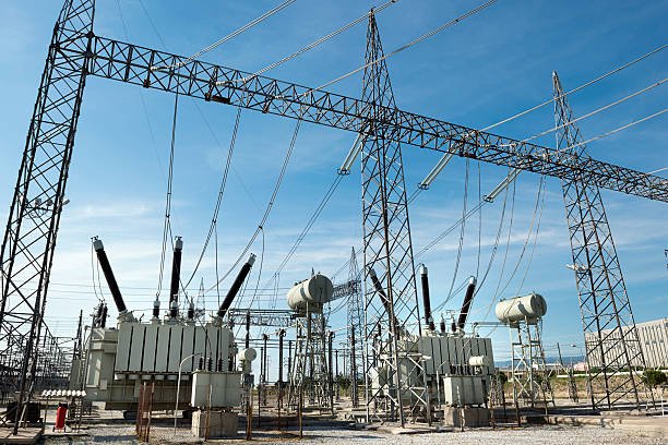
Choosing the wrong transformer impedance can create serious problems for electrical system performance, including excessive short-circuit current, poor voltage regulation, protection coordination issues, and difficulties operating transformers in parallel. Although buyers often focus on rated capacity, voltage, and efficiency, transformer impedance is equally important because it directly affects fault levels and voltage behavior under load. Understanding how to specify the correct impedance helps engineers and procurement teams select transformers that meet system requirements without compromising safety, reliability, or operating performance.
To choose the correct transformer impedance, buyers should evaluate the transformer’s rated capacity, primary and secondary voltages, permissible short-circuit current, voltage regulation requirements, protection settings, and whether the transformer will operate in parallel with other units. Transformer impedance is usually expressed as a percentage of rated impedance voltage and determines how much voltage is required to circulate rated current under short-circuit test conditions. Higher impedance generally limits fault current but can increase voltage drop, while lower impedance can improve voltage regulation but allow higher fault currents. The correct value must balance system protection, operating performance, and applicable standards.
Transformer impedance should never be selected in isolation. It must be coordinated with the upstream network, downstream equipment, switchgear ratings, protective devices, and any parallel transformers. The following outline explains the key technical considerations buyers should evaluate before finalizing transformer impedance specifications.
How Do You Choose the Correct Transformer Impedance Based on Rated Capacity and Voltage?
Choosing the wrong transformer impedance can create serious problems for an electrical system. Impedance that is too low may allow excessive short-circuit current, increasing stress on windings, cables, and switchgear. Impedance that is too high can cause greater voltage drop during heavy loading and may affect motor starting or sensitive equipment performance. Although rated capacity and voltage are important starting points, they do not determine the correct impedance by themselves.
To choose the correct transformer impedance, start with the rated kVA or MVA and primary and secondary voltages, then evaluate the required short-circuit current, available fault level, voltage regulation, downstream equipment ratings, and system coordination. Transformer impedance is usually specified as a percentage (%Z) on the transformer's rated base. The final value should satisfy the project's electrical design, manufacturer specifications, and applicable standards rather than follow a universal kVA-to-impedance rule.
For transformer buyers, electrical engineers, and system designers, understanding the relationship between impedance, capacity, voltage, and fault current helps prevent costly design mismatches. This guide explains how transformer impedance works, how to estimate its electrical effects, and what to confirm before placing an order.
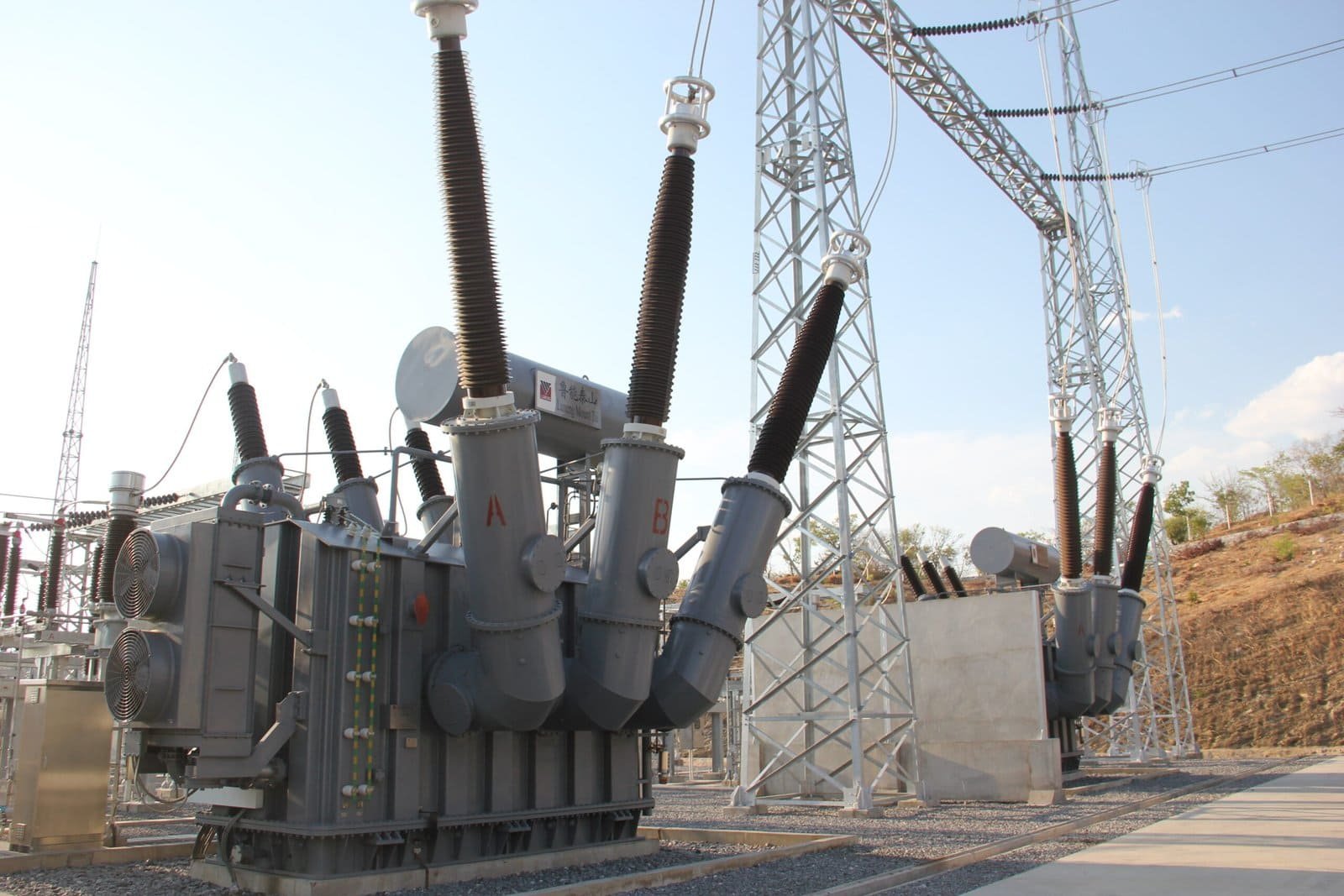
1. What Is Transformer Impedance?
Transformer impedance is the combined opposition to alternating current caused by winding resistance and leakage reactance. Resistance represents the real-power losses in the windings, while leakage reactance results from magnetic flux that does not link both windings.
Transformer manufacturers commonly express impedance as a percentage of rated voltage. Under the specified short-circuit test conditions, this percentage indicates the approximate fraction of rated voltage required to produce rated current when the other winding is appropriately short-circuited.
For example, a transformer with an impedance of 5% requires approximately 5% of its rated voltage to produce rated current under the applicable short-circuit test conditions.
Impedance influences several important operating characteristics:
- Short-circuit current at the transformer terminals.
- Voltage drop under load.
- Voltage regulation.
- Interaction with downstream protection and equipment.
- Parallel operation with other transformers.
A transformer’s impedance should therefore be considered a system design parameter, not simply a characteristic to minimize or maximize.
2. How Do Rated Capacity and Voltage Affect Impedance Selection?
Rated capacity and voltage establish the electrical base used to calculate current and interpret impedance. However, transformers with the same rated capacity and voltage may have different impedance values because of their design, application, and required fault-current performance.
Rated capacity
Transformer rated capacity, expressed in kVA or MVA, determines its rated current at a given voltage. For the same percentage impedance, a larger transformer generally has a higher rated current and can therefore deliver a higher prospective short-circuit current at its terminals.
Rated voltage
Voltage determines the current associated with a given apparent power and affects the voltage base used in impedance calculations. Primary and secondary voltages must be clearly specified because impedance values are meaningful only when their reference base is understood.
For a three-phase transformer, rated line current can be calculated using:
[\I_{\text{rated}}=\frac{S}{\sqrt{3},V_{LL}}]
Where:
- (I_{\text{rated}}) is rated line current in amperes.
- (S) is rated apparent power in volt-amperes.
- (V_{LL}) is rated line-to-line voltage in volts.
For example, a 1,000 kVA, 400 V three-phase transformer has a rated secondary current of approximately 1,443 A.
This rated current is a key starting point for estimating the short-circuit current associated with a specified impedance.
3. How Does Percentage Impedance Affect Short-Circuit Current?
For an idealized calculation with an effectively stiff upstream source, the symmetrical three-phase short-circuit current at the transformer terminals can be estimated as:
[\I_{\text{sc}}\approx I_{\text{rated}}\times\frac{100}{%Z}]
This estimate assumes the transformer is supplied at rated voltage and ignores upstream source impedance, cables, busbars, and other network impedances. The actual fault current will depend on the complete system.
Consider a 1,000 kVA, 400 V transformer with a rated secondary current of approximately 1,443 A.
| Transformer impedance | Approximate terminal short-circuit current |
|---|---|
| 4% | 36.1 kA |
| 5% | 28.9 kA |
| 6% | 24.1 kA |
| 8% | 18.0 kA |
These values are simplified estimates, not final protection-study results. They illustrate why impedance must be coordinated with switchgear interrupting ratings, busbar withstand capability, cable ratings, and protective devices.
Increasing transformer percentage impedance generally reduces the prospective short-circuit current at its terminals when other conditions remain unchanged.True
For a given rated current and an effectively stiff upstream source, the approximate short-circuit current is inversely proportional to percentage impedance. Actual fault current also depends on upstream and downstream circuit impedance.
4. How Does Impedance Affect Voltage Regulation?
Transformer impedance also affects voltage drop when the transformer supplies a load. The amount of voltage variation depends on impedance magnitude, its resistance-to-reactance ratio, load current, and load power factor.
A higher impedance generally produces greater voltage variation as load changes. This may matter when supplying motors, industrial processes, data centers, or sensitive electronic equipment.
A lower impedance can help reduce voltage drop, but it also increases the prospective short-circuit current. The design objective is to balance voltage performance and fault-current limitation.
| Application requirement | Impedance consideration |
|---|---|
| Sensitive electronic loads | Evaluate voltage regulation and load variation |
| Large motors | Assess starting current, starting voltage drop, and system stiffness |
| Industrial distribution | Coordinate voltage performance with switchgear fault ratings |
| Long secondary cable runs | Include cable impedance in voltage-drop and fault-current calculations |
| Transformers operating in parallel | Verify impedance compatibility, voltage ratio, phase displacement, and load-sharing requirements |
For demanding applications, engineers should perform load-flow, voltage-drop, and short-circuit studies rather than selecting impedance based on rated capacity alone.
5. What Other Factors Must Be Checked Before Ordering?
A reliable impedance specification requires more than a kVA rating and voltage ratio. Buyers should confirm the complete electrical and mechanical requirements with the manufacturer.
Key checks include:
- System fault level: Determine the available upstream short-circuit current and the required fault-current limitation.
- Protection coordination: Confirm that relays, fuses, and circuit breakers can detect and interrupt faults correctly.
- Equipment withstand ratings: Check switchgear, busbars, cables, and other connected equipment.
- Voltage regulation: Evaluate normal loading, peak loading, motor starting, and sensitive-load requirements.
- Parallel operation: Confirm compatible impedance values and other essential operating characteristics.
- Applicable standards: Specify the required IEC, IEEE, or local standards and project acceptance criteria.
- Manufacturer data: Request guaranteed impedance, tolerance, load-loss data, and applicable test reports.
Transformer impedance can affect load losses and design dimensions, but the relationship is not determined by impedance alone. Buyers should compare guaranteed performance data rather than assume that a higher or lower impedance automatically means a more efficient transformer.
6. A Practical Process for Selecting Transformer Impedance
Use the following sequence when preparing a transformer specification:
- Define the rating: Confirm kVA or MVA, primary voltage, secondary voltage, frequency, and phase configuration.
- Calculate rated current: Establish full-load current on the relevant side of the transformer.
- Determine fault-current limits: Review upstream fault levels and the withstand and interrupting ratings of connected equipment.
- Evaluate voltage performance: Check steady-state voltage drop, load variation, and motor-starting requirements.
- Check protection and system compatibility: Coordinate impedance with protection settings and any parallel-transformer requirements.
- Request a manufacturer recommendation: Specify the required impedance range and obtain guaranteed data for the proposed design.
- Verify the complete design: Confirm that the selected impedance meets project requirements through appropriate system calculations and factory documentation.
The final impedance value should be agreed upon before manufacturing because changing it can affect transformer design, losses, dimensions, cost, and electrical performance.
How Do You Choose the Correct Transformer Impedance to Control Short-Circuit Current?
Excessive short-circuit current can damage transformer windings, overstress busbars and cables, and exceed the interrupting capacity of circuit breakers. Selecting transformer impedance without calculating the available fault current can create expensive design problems and increase electrical safety risks. However, simply choosing the highest possible impedance is not always the right solution, because excessive impedance can cause voltage drop and affect motor starting and load performance.
To choose transformer impedance for short-circuit current control, calculate the transformer’s rated current, estimate the prospective fault current using its percentage impedance, and include upstream source and downstream circuit impedances for a more accurate result. Then select an impedance value that keeps fault current within equipment withstand and interrupting ratings while maintaining acceptable voltage regulation, motor-starting performance, protection coordination, and compliance with applicable standards.
For transformer buyers and electrical engineers, the goal is to balance fault-current limitation with reliable power delivery. The following guide explains the calculation method, practical selection factors, and information to confirm with a transformer manufacturer before ordering.
1. How Does Transformer Impedance Limit Short-Circuit Current?
Transformer impedance represents the combined effect of winding resistance and leakage reactance. During a short circuit, these characteristics oppose current flow and limit the current supplied by the transformer.
Transformer manufacturers usually specify impedance as a percentage of rated voltage. A transformer with a higher percentage impedance generally supplies less short-circuit current than a transformer with a lower percentage impedance, assuming the same rated current and otherwise comparable conditions.
For a preliminary estimate of a three-phase fault at the transformer terminals, with an effectively stiff upstream source:
[\I_{\mathrm{sc}}\approx I_{\mathrm{rated}}\times\frac{100}{%Z}]
Where:
- (I_{\mathrm{sc}}) is the estimated symmetrical short-circuit current.
- (I_{\mathrm{rated}}) is the rated current on the side being evaluated.
- (%Z) is the transformer percentage impedance.
This formula is useful for initial screening, but it does not account for upstream source impedance, cable impedance, or other network elements. A complete fault study should include these factors.
2. How Do You Calculate the Required Impedance?
Start by calculating the transformer’s rated current. For a three-phase transformer:
[\I_{\mathrm{rated}}=\frac{S}{\sqrt{3},V_{LL}}]
Here, (S) is rated apparent power in volt-amperes and (V_{LL}) is line-to-line voltage in volts.
The simplified relationship can then be rearranged to estimate the minimum impedance needed to limit the terminal fault current to a target value:
[\%Z_{\mathrm{required}}\approx\
\frac{100,I_{\mathrm{rated}}}{I_{\mathrm{sc,target}}}]
This estimate assumes the upstream source is effectively stiff. If the source impedance is significant, the actual fault current will be lower than the simple transformer-only estimate, and the required transformer impedance should be determined from the full network calculation.
Example: A 1,000 kVA, 400 V transformer
Assume a three-phase transformer has a rated capacity of 1,000 kVA and a secondary voltage of 400 V.
Its rated secondary current is approximately:
[\I_{\mathrm{rated}}=\frac{1{,}000{,}000}{\sqrt{3}\times400}\
\approx1{,}443\text{ A}]
If the transformer has 5% impedance, the approximate terminal short-circuit current is:
[\I_{\mathrm{sc}}\approx1{,}443\times\frac{100}{5}\
\approx28.9\text{ kA}]
If a preliminary target is 25 kA, the transformer-only estimate gives:
[\%Z_{\mathrm{required}}\approx\
\frac{100\times1{,}443}{25{,}000}\
\approx5.77%]
This suggests that an impedance around 5.8% or higher would be needed under the simplified assumptions. It is not, by itself, a final specification: upstream impedance, tolerances, system operating conditions, and the equipment’s actual fault ratings must still be evaluated.
3. How Does Impedance Change the Available Fault Current?
The following table illustrates the effect of percentage impedance for the same 1,000 kVA, 400 V transformer with a rated secondary current of approximately 1,443 A.
| Transformer impedance | Approximate terminal short-circuit current |
|---|---|
| 4% | 36.1 kA |
| 5% | 28.9 kA |
| 6% | 24.1 kA |
| 7% | 20.6 kA |
| 8% | 18.0 kA |
These are idealized estimates that exclude upstream and downstream impedance. Actual fault current must be calculated using the relevant network configuration and applicable short-circuit method.
Increasing transformer percentage impedance generally reduces the prospective short-circuit current at its terminals when other conditions remain unchanged.True
For a given rated current and an effectively stiff upstream source, the approximate short-circuit current is inversely proportional to percentage impedance. Actual fault current also depends on source and circuit impedance.
4. What Factors Should Guide Impedance Selection?
Short-circuit current is only one part of the selection process. A transformer impedance value that satisfies the fault-current limit must also support acceptable operating performance.
| Selection factor | What to evaluate | Why it matters |
|---|---|---|
| Switchgear interrupting rating | Maximum prospective fault current at each bus | Ensures circuit breakers can interrupt the fault |
| Equipment withstand rating | Short-time and peak-current capability of busbars, cables, and connected equipment | Limits thermal and mechanical damage |
| Voltage regulation | Voltage drop under expected load and power factor | Protects load performance |
| Motor starting | Starting current and voltage dip | Helps prevent motor-starting problems |
| Protection coordination | Relay, fuse, and breaker operating characteristics | Supports selective and reliable fault clearing |
| Parallel transformers | Impedance magnitude, ratio, phase displacement, and other compatibility requirements | Helps achieve suitable load sharing |
| System expansion | Expected future capacity and changes to network fault level | Reduces the risk of an undersized or unsuitable design |
Higher impedance generally reduces fault current, but it can also increase load-related voltage drop. The best value is therefore the one that meets the complete system requirements, not simply the value that produces the lowest calculated fault current.
5. How Should Buyers Coordinate Impedance With Protection Equipment?
Before specifying a transformer, buyers should obtain the available short-circuit current at the point of connection and confirm the ratings of downstream equipment. The calculation should consider credible operating configurations, including parallel sources, alternate supply paths, and future system expansion where relevant.
Circuit breakers must have an adequate interrupting rating for the calculated fault current. Busbars, cables, and other components must also withstand the thermal and mechanical effects of the fault until the protective device clears it.
Protection settings must be reviewed alongside the transformer impedance. Increasing impedance may reduce fault current, but it can also affect the magnitude of fault current seen by protection devices. A qualified engineer should verify that faults can still be detected and cleared within the required time.
For procurement, the specification should clearly state the required impedance or acceptable range, the applicable standard, relevant tolerances, and the conditions under which the fault-current calculation was performed.
6. What Information Should You Provide to the Manufacturer?
To receive a suitable recommendation, prepare the following information:
- Transformer rated capacity in kVA or MVA.
- Primary and secondary voltage ratings.
- Three-phase system frequency and connection arrangement.
- Available upstream short-circuit level or source impedance.
- Target maximum fault current at the transformer terminals or downstream bus.
- Switchgear interrupting and equipment withstand ratings.
- Expected load profile, motor-starting requirements, and voltage-regulation limits.
- Any parallel-transformer operation or future expansion plans.
The manufacturer can use these details to evaluate feasible impedance options and explain the related design trade-offs. Final approval should be based on a documented system study and verified equipment ratings.
How Do You Choose the Correct Transformer Impedance to Maintain Voltage Regulation?
Poor transformer impedance selection can cause excessive voltage drop when loads increase, unstable voltage at sensitive equipment, and difficulties starting large motors. Choosing an impedance that is too low may improve voltage regulation but increase short-circuit current beyond the capacity of downstream equipment. The challenge is to maintain acceptable voltage under real operating conditions without compromising electrical safety or protection coordination.
To choose transformer impedance for good voltage regulation, evaluate the transformer's rated capacity, primary and secondary voltages, expected load current, load power factor, allowable voltage drop, and available short-circuit current. Lower percentage impedance generally reduces the transformer’s internal voltage drop, while higher impedance generally limits fault current but increases load-related voltage variation. The correct value must balance these requirements and be verified through transformer voltage-regulation calculations and system studies.
For transformer buyers, electrical engineers, and industrial power users, impedance should be selected according to the complete application rather than rated capacity alone. This guide explains the relationship between impedance and voltage regulation, provides a practical calculation example, and outlines the key checks to complete before ordering a transformer.
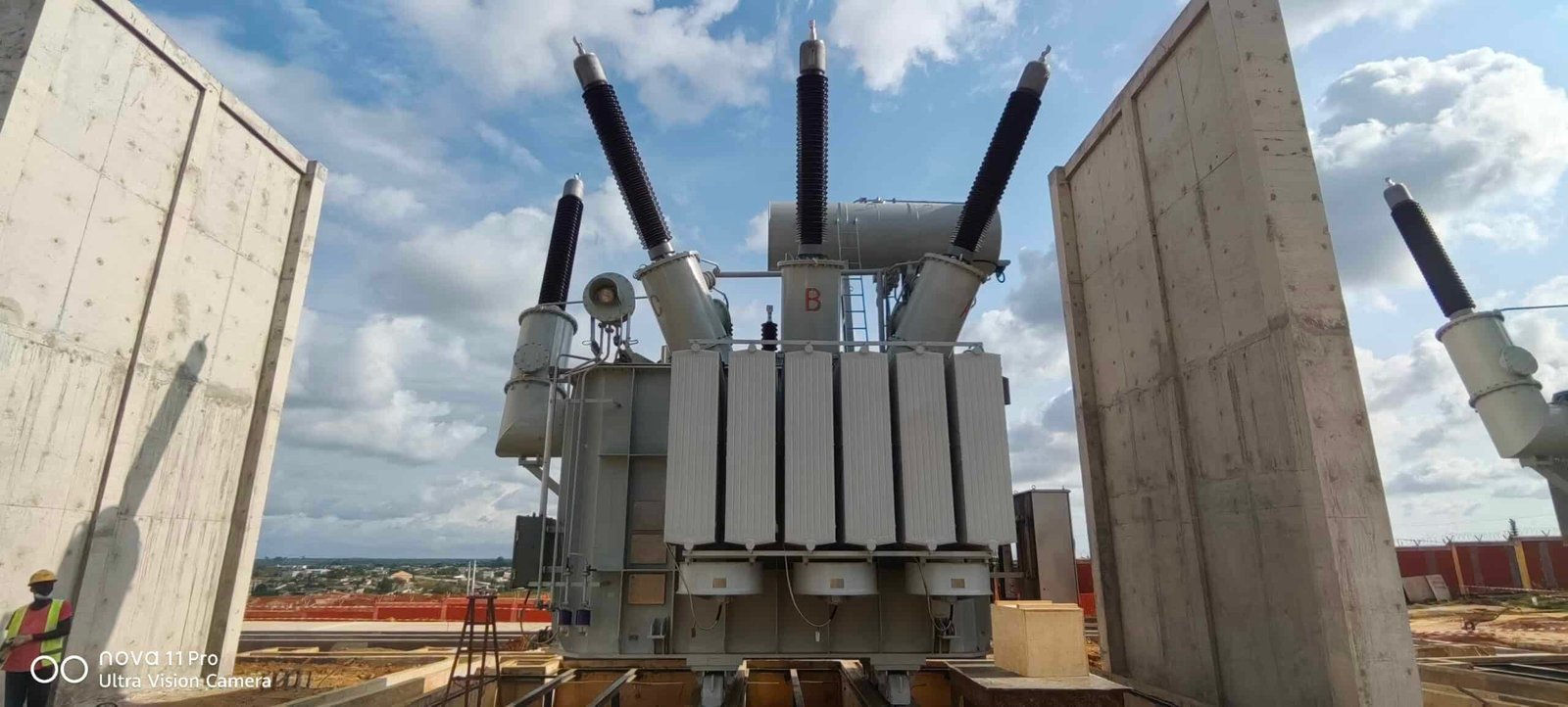
1. What Is the Relationship Between Transformer Impedance and Voltage Regulation?
Transformer impedance consists of winding resistance and leakage reactance. Both contribute to the voltage difference between no-load and loaded operating conditions.
When a transformer supplies current, voltage drops across its internal impedance. The amount of voltage variation depends on the load current, the impedance magnitude, the resistance-to-reactance ratio, and the load power factor.
In general:
- Lower percentage impedance tends to reduce internal voltage drop and increase the prospective short-circuit current.
- Higher percentage impedance tends to increase load-related voltage variation and reduce the prospective short-circuit current.
- Power factor affects how resistance and reactance contribute to voltage regulation.
For many conventional transformers supplying inductive loads, voltage regulation worsens as lagging load current increases. However, the exact relationship depends on the transformer’s impedance components and operating conditions.
A transformer with lower percentage impedance generally has better voltage regulation when other design and operating conditions are comparable.True
Lower impedance generally produces a smaller internal voltage drop at a given current, although actual regulation also depends on the resistance-to-reactance ratio, load power factor, and operating conditions.
2. How Do You Calculate Transformer Voltage Regulation?
Voltage regulation is commonly expressed as the percentage change between no-load secondary voltage and loaded secondary voltage, with the primary voltage maintained at its specified value.
[\text{Voltage Regulation}(%)=\
\frac{V_{\text{no-load}}-V_{\text{full-load}}}\
{V_{\text{full-load}}}\times100]
Here, both secondary voltages are measured on the same voltage basis. Some specifications use rated voltage as the denominator, so buyers should confirm the definition used in the project documents.
For a preliminary engineering estimate, transformer impedance and load power factor can be used to approximate regulation:
[\text{VR}(%)\approx\
R_{%}\cos\phi+X_{%}\sin\phi]
This simplified expression applies to a lagging power factor under the usual small-voltage-drop approximation. (R_{%}) and (X_{%}) are the resistive and reactive components expressed on the same percentage base, and (\phi) is the load power-factor angle. For a leading power factor, the reactive term changes sign.
The approximation helps compare design options, but it does not replace a complete calculation when voltage limits are strict or the load profile is complex.
3. How Does Load Power Factor Affect Impedance Selection?
A transformer may exhibit different voltage regulation at the same load current depending on whether the load has a lagging, unity, or leading power factor.
| Load condition | General voltage-regulation effect | Selection consideration |
|---|---|---|
| Lagging power factor | Leakage reactance usually contributes positively to voltage drop | Common for motors and inductive industrial loads |
| Unity power factor | Reactive contribution is small | Resistance-related drop becomes more prominent |
| Leading power factor | Reactive contribution can offset part of the resistive voltage drop | Evaluate carefully because regulation may become negative |
For example, a facility with large induction motors may experience significant voltage drop during starting. A data center or industrial process with strict voltage limits may require careful assessment of both steady-state and transient performance.
Buyers should provide the manufacturer with expected load power factor, demand profile, motor-starting information, and allowable voltage variation. A transformer chosen using only rated kVA and nominal voltage may not deliver the required performance under the actual load.
4. How Do You Balance Voltage Regulation and Short-Circuit Current?
Impedance selection is a trade-off. Reducing impedance can improve voltage regulation, but it also increases prospective fault current. Increasing impedance can limit fault current, but may create excessive voltage drop at high loading.
Consider a 1,000 kVA, 400 V three-phase transformer. Its rated secondary current is approximately:
[\I_{\text{rated}}=\
\frac{1{,}000{,}000}{\sqrt{3}\times400}\
\approx1{,}443\text{ A}]
With an effectively stiff upstream source, the simplified transformer-terminal short-circuit current is approximately:
[\I_{\text{sc}}\approx I_{\text{rated}}\times\frac{100}{%Z}]
| Percentage impedance | Approximate short-circuit current |
|---|---|
| 4% | 36.1 kA |
| 5% | 28.9 kA |
| 6% | 24.1 kA |
| 7% | 20.6 kA |
These figures are illustrative estimates that exclude upstream and downstream impedance. They show why the lowest-impedance option should not automatically be selected.
The final design must meet the project's voltage-regulation limits while keeping fault current within the interrupting and withstand ratings of connected equipment. Protection coordination, cable voltage drop, and any parallel supply paths must also be considered.
5. What Should Buyers Check Before Specifying Transformer Impedance?
Before approving a transformer specification, buyers should confirm the following:
| Requirement | What to verify |
|---|---|
| Rated capacity and voltage | kVA or MVA rating and primary and secondary voltage |
| Impedance specification | Guaranteed percentage impedance and applicable tolerance |
| Voltage regulation | Expected full-load regulation at relevant power factors |
| Load characteristics | Demand profile, motor starting, and sensitive equipment requirements |
| Short-circuit performance | Available fault current and equipment ratings |
| Loss performance | Guaranteed load losses and efficiency requirements |
| Applicable standards | Relevant IEC, IEEE, or local requirements |
| Factory documentation | Routine test reports and verified impedance data |
Ask the manufacturer to state the conditions and assumptions used for voltage-regulation figures. If the application includes large motors, nonlinear loads, long secondary cables, or stringent voltage limits, request a more detailed system evaluation rather than relying solely on a typical impedance value.
6. A Practical Method for Selecting the Correct Impedance
A reliable selection process follows these steps:
- Define the electrical requirements. Confirm capacity, voltage ratio, frequency, connection, and expected operating conditions.
- Establish voltage limits. Identify acceptable voltage variation at full load, during motor starting, and under relevant load changes.
- Determine load power factor. Evaluate the expected mix of inductive, resistive, and potentially leading loads.
- Calculate voltage regulation. Use the transformer's resistance and reactance data to estimate performance.
- Calculate short-circuit current. Include upstream source impedance and downstream circuit impedance where applicable.
- Coordinate protection. Verify that switchgear, cables, busbars, and protective devices are suitable for the calculated fault levels.
- Confirm the specification with the manufacturer. Review guaranteed impedance, losses, test results, and any special performance requirements.
How Do You Choose the Correct Transformer Impedance for Parallel Transformer Operation?
Operating transformers in parallel can increase available capacity, improve supply continuity, and provide flexibility during maintenance or changing demand. However, transformers with incompatible impedance values may not share load evenly. One unit can become overloaded while another remains underused, increasing losses, operating temperature, and insulation aging. Incorrect parallel connections can also create circulating currents or serious fault conditions.
To choose transformer impedance for parallel operation, select units with compatible percentage impedance and impedance angle, matching voltage ratios and tap settings, the same phase sequence and phase displacement, and suitable kVA ratings. Compatible impedance helps transformers share load according to their ratings and reduces the risk of circulating currents and unequal loading. The final selection must be verified against manufacturer data and the electrical system's operating and protection requirements.
For transformer buyers and electrical engineers, impedance compatibility is essential when expanding a substation, adding a second transformer, or replacing an existing unit. The following guide explains the key requirements, how impedance affects load sharing, and what to verify before connecting transformers in parallel.
1. Why Does Transformer Impedance Matter in Parallel Operation?
When two transformers supply a common bus, their currents depend partly on their impedances. For transformers with compatible voltage ratios and phase relationships, the unit with lower impedance relative to its rating generally carries a greater share of the load.
If the impedances differ significantly, load distribution may not follow the transformers' kVA ratings. A smaller transformer with relatively low impedance can carry a disproportionate amount of current and exceed its rated capacity before the combined system reaches its total rated load.
Impedance also includes both resistance and reactance. Therefore, comparing percentage impedance alone may not be sufficient: differences in the impedance angle can affect current distribution and power sharing.
2. What Impedance Matching Is Required?
For satisfactory parallel operation, transformers should have compatible percentage impedance values and resistance-to-reactance ratios. The acceptable difference depends on the transformer ratings, design, manufacturer specifications, and the project's load-sharing requirements.
| Parameter | Preferred condition | Why it matters |
|---|---|---|
| Percentage impedance | Similar values on a common rating basis | Supports predictable load sharing |
| Impedance angle or X/R ratio | Compatible values | Helps achieve suitable current and power sharing |
| Rated capacity | Equal or appropriately matched ratings | Reduces the risk of overloading one unit |
| Voltage ratio | Matching primary and secondary ratios | Limits circulating current caused by voltage differences |
| Tap settings | Compatible secondary voltages | Helps maintain balanced load sharing |
| Phase sequence and phase displacement | Compatible connections and vector groups | Prevents severe circulating currents or short-circuit conditions |
| Polarity and winding connections | Correctly verified | Ensures safe electrical interconnection |
Transformers do not always need identical kVA ratings or exactly identical impedance values. Different-rated units can operate in parallel when their electrical characteristics are compatible and the resulting load distribution remains within each unit's limits.
3. How Does Percentage Impedance Affect Load Sharing?
Consider two transformers connected to the same secondary bus. Assume their voltage ratios and phase relationships match, their impedances are expressed on a common voltage base, and the load is shared under comparable operating conditions.
For a simplified comparison, current divides approximately in inverse proportion to each transformer's impedance. In practical systems, the impedance values must be converted to a consistent base before comparing them.
Example: Two equal-rated transformers
Suppose two 1,000 kVA transformers have compatible voltage ratios and impedance angles:
- Transformer A: 5% impedance
- Transformer B: 6% impedance
Because Transformer A has lower impedance, it will generally carry more current than Transformer B. The exact load split depends on the transformers' actual impedance magnitudes and angles.
If the transformers have significantly different impedance values, the lower-impedance unit may reach its rated current before the combined load reaches 2,000 kVA. Engineers should calculate the expected current in each transformer rather than assuming that two 1,000 kVA units can always supply 2,000 kVA of usable load in parallel.
Two transformers with the same kVA rating and voltage ratio will always share load equally when connected in parallel.False
Equal load sharing also depends on impedance magnitude and angle, tap settings, winding connections, and other electrical characteristics. Differences can cause unequal loading even when rated capacity and voltage ratio match.
4. How Do Different Transformer Ratings Affect Impedance Selection?
Transformers with different rated capacities can sometimes operate in parallel, but their impedance values must be evaluated relative to their own ratings.
For example, a 1,000 kVA transformer and a 500 kVA transformer may have different percentage impedance values yet still share load appropriately if their per-unit impedances on a common base are compatible. Comparing the percentage values without considering the rating base can be misleading.
Buyers should request the manufacturer's impedance data and have the engineer calculate the expected load split at minimum, normal, and maximum system demand.
| Parallel arrangement | Main consideration |
|---|---|
| Equal-rated transformers with similar impedance | Usually easier to configure for balanced loading |
| Equal-rated transformers with different impedance | May produce unequal current sharing |
| Different-rated transformers | Requires careful per-unit impedance conversion and load-sharing calculations |
| Transformers with different X/R ratios | May have different current and power-sharing behavior |
| Existing transformer plus replacement unit | Verify impedance, ratio, tap range, vector group, and connection compatibility |
A transformer should not be approved for parallel operation based on a general rule alone. The complete electrical characteristics and operating limits must be checked.
5. What Other Requirements Must Be Checked Before Paralleling Transformers?
Impedance matching is only one part of the parallel-operation assessment. A voltage-ratio mismatch can create circulating current even when there is little or no external load. Incorrect phase displacement or phase sequence can create dangerous current paths when the secondary windings are connected.
Before energizing a parallel arrangement, verify:
- Voltage ratio: Confirm compatible primary and secondary ratings.
- Tap positions: Ensure the selected taps produce compatible secondary voltages.
- Vector group: Confirm the required phase displacement is compatible.
- Phase sequence and polarity: Verify connections before closing the parallel circuit.
- Impedance data: Compare magnitude and angle on a consistent base.
- Protection coordination: Review fault levels, relay settings, and circuit-breaker ratings.
- Thermal capacity: Confirm that each transformer remains within its rated loading and temperature limits.
- Manufacturer guidance: Follow the approved connection and commissioning procedures.
Commissioning tests should be carried out by qualified personnel using appropriate safety procedures and the project-approved method.
6. What Should Buyers Ask the Transformer Manufacturer?
When purchasing a transformer intended for parallel operation, tell the supplier whether the unit will operate with an existing transformer or with another new unit.
Provide the rated capacities, primary and secondary voltages, vector groups, existing percentage impedance, tap settings, available fault level, and expected loading profile. Request guaranteed impedance data, the applicable tolerance, and relevant routine test reports.
For an existing installation, actual nameplate information and test records are particularly important. A replacement transformer with a different impedance may require a revised load-sharing assessment or other system modifications.
How Do You Choose the Correct Transformer Impedance Based on Protection Coordination and Applicable Standards?
Choosing transformer impedance without considering protection coordination can create serious problems for an electrical system. If the impedance is too low, the transformer may deliver excessive short-circuit current, potentially exceeding the interrupting capacity of circuit breakers and the withstand ratings of downstream equipment. If it is too high, fault current may become insufficient for protective devices to operate quickly and selectively. Either condition can increase equipment damage, outage duration, and safety risks. The correct approach is to evaluate transformer impedance alongside fault-current calculations, protective-device settings, equipment ratings, and applicable electrical standards before finalizing the design.
The correct transformer impedance is the value that satisfies the system’s voltage-regulation requirements, limits prospective fault current to acceptable levels, and allows protective devices to detect and clear faults selectively within their required operating times. Engineers should verify the selected impedance against transformer specifications, short-circuit studies, protection-coordination curves, equipment withstand ratings, and applicable standards such as IEEE C57.12.00, IEEE C57.12.90, IEC 60076, and the locally adopted electrical code.
For electrical engineers, project designers, and procurement teams, transformer impedance is not simply a percentage printed on a nameplate. It directly affects the interaction between the transformer and the entire protection system. The following guide explains how to evaluate transformer impedance systematically, what standards to check, and how to avoid common selection mistakes.

1. Understand How Transformer Impedance Affects Protection Coordination
Transformer impedance, usually expressed as a percentage of rated impedance (%Z), represents the transformer's internal opposition to current flow under AC operating conditions. Its magnitude strongly influences the short-circuit current available at the secondary terminals and, consequently, the operating conditions of protective devices.
For a simplified three-phase transformer, the approximate symmetrical three-phase short-circuit current at the secondary terminals can be estimated using:
[\I_{\mathrm{sc}} \approx I_{\mathrm{rated}}\frac{100}{%Z}]
This approximation assumes an effectively infinite upstream source and neglects additional source and circuit impedance. Actual fault current must be calculated using the complete system impedance, including the utility source, upstream transformers, cables, and other relevant components.
For example, consider a 1,000 kVA transformer with a 480 V three-phase secondary and 5.75% impedance.
The rated secondary current is:
[\I_{\mathrm{rated}}=\frac{1{,}000{,}000}{\sqrt{3}\times480}\
\approx1{,}203\text{ A}]
The approximate terminal short-circuit current is:
[\I_{\mathrm{sc}}\approx1{,}203\times\frac{100}{5.75}\
\approx20{,}922\text{ A}]
This indicates approximately 20.9 kA of symmetrical RMS fault current at the transformer terminals under the stated assumptions.
Transformer impedance directly affects the prospective short-circuit current available at its terminals.True
For a given rated voltage and capacity, greater transformer impedance generally reduces the fault current contribution, although the complete system impedance determines the actual result.
A protection engineer must use this information to check whether circuit breakers can interrupt the available current, whether busbars and conductors can withstand the associated thermal and mechanical stresses, and whether protective relays can detect faults within the required time.
2. Evaluate the Main Protection Requirements Before Selecting %Z
The correct transformer impedance is a coordinated design decision rather than a standalone preference. Before choosing a target value, identify the protection devices, fault scenarios, and equipment limitations that govern the installation.
| Protection consideration | Effect of transformer impedance | Required engineering check |
|---|---|---|
| Circuit-breaker interrupting rating | Lower impedance generally increases available fault current | Confirm the calculated fault duty does not exceed the device's applicable interrupting rating |
| Busbar and conductor withstand | Higher fault current increases thermal and electromechanical stress | Verify short-time withstand, peak withstand, and clearing time |
| Protective-relay sensitivity | Higher impedance can reduce current for remote faults | Confirm minimum fault current remains detectable |
| Selective coordination | Impedance changes fault-current levels and device operating points | Compare time-current curves and relevant relay operating characteristics |
| Transformer damage protection | Fault duration and current affect transformer stress | Check transformer damage curves and manufacturer protection guidance |
| Ground-fault protection | Grounding arrangement and zero-sequence impedance affect earth-fault current | Evaluate the actual grounding method and ground-fault network |
| Arc-flash risk | Fault current influences incident energy, but not in a simple one-direction relationship | Perform an arc-flash study using the calculated current and actual clearing times |
A key distinction is that lower fault current does not automatically mean lower arc-flash incident energy. A lower current can cause some protective devices to operate more slowly, potentially increasing incident energy. The effect depends on the device type, settings, and arc-fault calculation method.
3. Check Applicable Transformer and Electrical Standards
Applicable standards depend on the country, project specifications, transformer type, voltage class, and installation environment. Standards may specify transformer design, test methods, impedance tolerances, short-circuit withstand, or installation requirements, but they do not necessarily prescribe one universal impedance percentage for every application.
| Standard or requirement | Main relevance | How it supports selection |
|---|---|---|
| IEEE C57.12.00 | General requirements for liquid-immersed distribution, power, and regulating transformers within its scope | Establishes relevant transformer performance and design requirements |
| IEEE C57.12.90 | Test code for liquid-immersed distribution, power, and regulating transformers | Provides test methods for verifying impedance and other transformer characteristics |
| IEC 60076 series | Power-transformer requirements and tests | Supports specification, performance verification, and short-circuit considerations according to the applicable part |
| IEEE C37 series | Circuit breakers and switchgear, with individual documents covering specific equipment | Helps establish applicable switching-device performance and rating requirements |
| IEC 60909 series | Short-circuit current calculation in three-phase AC systems | Provides a recognized method for calculating fault current where applicable |
| IEEE 1584 | Arc-flash hazard calculations | Supports evaluation of incident energy and protection clearing time |
| NFPA 70 / NEC, where adopted | Electrical installation requirements in the United States | Provides applicable installation, overcurrent protection, and equipment requirements |
The precise edition and applicability of each standard should be confirmed during project design. Local regulations, utility requirements, owner specifications, and authority-having-jurisdiction requirements may impose additional conditions.
IEC 60076 or IEEE C57 standards prescribe one universal transformer impedance percentage suitable for every electrical system.False
These standards address transformer requirements and testing within their respective scopes, but the appropriate impedance for a particular installation depends on system studies, equipment ratings, protection requirements, and project specifications.
4. Perform a Short-Circuit Study and Review Protective-Device Coordination
Once the preliminary impedance range is identified, engineers should calculate fault current at relevant points throughout the network. The study should include maximum and minimum operating conditions where they affect equipment ratings or protective-device sensitivity.
Maximum fault-current assessment
The maximum available fault current is used to verify the interrupting and withstand capability of circuit breakers, switchgear, busbars, cables, and the transformer itself. Consider the strongest credible upstream source, parallel sources, motor contributions where relevant, and other applicable operating configurations.
If the transformer impedance is reduced, the resulting fault current may exceed an existing switchgear rating. In that case, engineers may need to consider a higher-impedance transformer, appropriately rated equipment, or a validated current-limiting solution.
Minimum fault-current assessment
Minimum fault current is equally important for protective sensitivity. Consider weaker upstream sources, remote faults, alternate configurations, and ground-fault conditions.
If impedance is too high, a downstream overcurrent device may not reach its pickup threshold promptly, especially for remote faults or high-resistance faults. This can undermine protection sensitivity and delay fault clearing.
Time-current coordination
Protective devices should be evaluated using their time-current characteristic curves or the appropriate relay coordination methods. The objective is to have the device nearest the fault clear it first, while upstream devices provide suitable backup protection.
Coordination should account for:
- Transformer full-load current and allowable loading.
- Transformer inrush current and energization conditions.
- Downstream equipment damage curves.
- Cable and busbar thermal withstand.
- Relay pickup, time-delay, and instantaneous settings.
- Fuse characteristics and circuit-breaker tolerances.
- Transformer through-fault withstand and damage limits.
- Selective-coordination requirements imposed by the project or code.
Do not select impedance solely to achieve a desired breaker trip time. Protective settings, transformer characteristics, and equipment ratings must be evaluated together.
5. Compare Candidate Impedance Values
A practical selection study often compares several available transformer designs rather than assuming that a single percentage is correct from the beginning.
The following example is illustrative and assumes the same 1,000 kVA, 480 V transformer used earlier. It uses an idealized infinite-source model to show the relationship between impedance and terminal fault current.
| Transformer impedance | Approximate terminal fault current | Potential advantage | Potential concern |
|---|---|---|---|
| 4.5% | 26.7 kA | Lower internal voltage drop under load | Higher fault duty may exceed equipment ratings |
| 5.75% | 20.9 kA | Intermediate fault-current level | Must still be checked against actual coordination and withstand requirements |
| 7.0% | 17.2 kA | Lower approximate terminal fault current | Greater voltage drop and potentially reduced protection sensitivity |
These values are not universal recommendations. Actual transformer availability, guaranteed impedance, impedance tolerance, upstream source impedance, and system configuration must be considered.
A higher impedance may reduce fault current but increase voltage drop during heavy loading or motor starting. A lower impedance may improve voltage performance while increasing fault duty. The selected value must satisfy both operating and fault conditions.
6. Consider Ground-Fault Protection Separately
Three-phase bolted-fault calculations do not fully describe ground-fault behavior. Ground-fault current depends on the transformer winding connection, neutral grounding method, zero-sequence impedance, and the grounding transformer or grounding resistor where installed.
For example, a delta-wye transformer, a grounded-wye system, and a resistance-grounded system can have very different ground-fault current levels even when their positive-sequence transformer impedances are similar.
Where a grounding transformer is part of the design, engineers should evaluate its impedance and thermal rating alongside the grounding resistor, neutral-grounding arrangement, and ground-fault relay settings. The goal is to provide enough current for reliable detection without exceeding the intended ground-fault current or equipment limits.
Ground-fault protection should therefore be verified with the applicable sequence-network model rather than inferred from the transformer’s nameplate %Z alone.
7. Verify the Impedance Specification With the Transformer Manufacturer
After the system studies establish an acceptable impedance range, the transformer specification should define the requirements clearly enough for manufacturers to design and test the unit accordingly.
Include the following information in the request for quotation:
- Rated kVA or MVA, primary voltage, secondary voltage, and frequency.
- Winding connection and vector group, where applicable.
- Target percentage impedance and the reference temperature or test basis required by the governing specification.
- Applicable impedance tolerance and guaranteed test values.
- Tap range and the impedance basis for relevant tap positions.
- Cooling method, insulation system, and service conditions.
- Required short-circuit withstand capability.
- Applicable transformer standards and required routine or type tests.
- Available fault-current study results and protection-coordination requirements.
Ask the manufacturer to confirm the guaranteed impedance, allowable tolerance, test method, and any design implications of the requested value. Impedance tolerances can matter in parallel transformer operation and in protection studies, so the study should use defensible manufacturer data rather than an assumed exact value.
8. Common Selection Mistakes to Avoid
Choosing the lowest available impedance by default. This can increase fault duty and force costly upgrades to switchgear or other equipment.
Choosing the highest impedance to minimize fault current. Excessive impedance may cause unacceptable voltage drop, motor-starting difficulties, or insufficient fault current for protective-device operation.
Checking only the transformer terminals. Fault levels at downstream buses can differ because cables, reactors, upstream sources, and other components contribute impedance.
Ignoring transformer inrush. Protection settings must distinguish normal energization current from fault conditions using suitable methods.
Treating ground faults as ordinary three-phase faults. Grounding configuration and zero-sequence impedance can substantially change fault current.
Relying on standards without a system study. Standards establish requirements and calculation or testing methods; engineering analysis determines whether a particular impedance is suitable for the installation.
How Can Buyers Verify the Correct Transformer Impedance Before Purchasing a Transformer?
Purchasing a transformer with the wrong impedance can create costly problems long after delivery. An impedance value that is too low may increase short-circuit current beyond the capacity of existing switchgear, while an excessively high value can contribute to voltage drop, motor-starting difficulties, or inadequate protective-device sensitivity. If buyers rely only on a quotation or a nameplate percentage, they may discover these problems after installation, when corrective action is expensive and disruptive. The best way to avoid this risk is to verify the specified transformer impedance through engineering calculations, manufacturer documentation, applicable standards, and documented test results before approving the purchase.
To verify the correct transformer impedance before purchasing, buyers should confirm the required percentage impedance (%Z) through a system study, check that the value matches the project specification and equipment ratings, review the manufacturer's guaranteed technical data and impedance tolerance, verify the applicable test standard, and require documented impedance test results before shipment. The final selection must satisfy short-circuit, voltage-regulation, protection-coordination, and operating requirements.
Transformer impedance is not simply a number to compare between supplier quotations. It affects how the transformer performs under load, how much fault current it can supply, and how the electrical protection system responds to abnormal conditions. This guide provides a practical verification process that purchasing teams, electrical engineers, EPC contractors, and facility owners can use before placing an order.

1. Confirm the Required Impedance Before Requesting Quotations
The first step is to establish the required transformer impedance independently of the supplier's proposed design. Buyers should ask the project engineer or electrical consultant to confirm the acceptable impedance range based on the electrical system design.
The review should cover:
- Rated power and primary and secondary voltages.
- Expected operating load and allowable voltage drop.
- Maximum prospective short-circuit current.
- Circuit-breaker interrupting ratings and equipment withstand limits.
- Protective-device coordination and minimum fault-current sensitivity.
- Motor-starting requirements, if applicable.
- Parallel operation with existing or future transformers.
- Applicable utility, owner, and regulatory requirements.
For a simplified three-phase transformer, the approximate symmetrical short-circuit current at the secondary terminals can be estimated as:
[\I_{\mathrm{sc}}\approx I_{\mathrm{rated}}\frac{100}{%Z}]
This estimate assumes an effectively infinite upstream source and neglects other circuit impedances. The actual fault current must be calculated using the complete system impedance.
For example, a 1,000 kVA, 480 V three-phase transformer has a rated secondary current of approximately 1,203 A. If its impedance is 5.75%, its simplified terminal short-circuit current is:
[\I_{\mathrm{sc}}\approx1{,}203\times\frac{100}{5.75}\
\approx20.9\text{ kA}]
This result provides an initial screening value. It does not replace a complete short-circuit study that includes upstream sources, cables, motors, and other relevant contributions.
2. Compare the Supplier's Quotation With the Approved Specification
Once the design requirements are established, compare every supplier quotation against the same technical specification. A quotation that lists only transformer capacity and voltage is insufficient for a meaningful technical comparison.
| Item to verify | What buyers should confirm | Why it matters |
|---|---|---|
| Rated capacity | kVA or MVA rating | Establishes the transformer's power rating and rated current |
| Voltage ratio | Primary and secondary rated voltages | Ensures compatibility with the electrical system |
| Percentage impedance | Guaranteed %Z value | Influences short-circuit current and voltage regulation |
| Impedance tolerance | Permitted deviation from the guaranteed value | Helps establish realistic fault-current and parallel-operation conditions |
| Winding connection | Delta, grounded wye, or other specified configuration | Affects grounding and fault-current behavior |
| Tap range | Tap positions and associated impedance basis | Supports voltage adjustment and accurate study assumptions |
| Applicable standards | Correct standard and edition for the transformer type | Defines relevant design and testing requirements |
| Test documentation | Required routine-test report and acceptance criteria | Provides evidence that the supplied unit meets the contract |
Do not assume that two transformers with identical kVA and voltage ratings are interchangeable. Differences in impedance, winding arrangement, taps, and other characteristics may affect system compatibility.
3. Check the Applicable Standards and Test Requirements
The purchase specification should identify the standards that apply to the transformer type, location, and project. Common references include the IEC 60076 series for power transformers and IEEE C57.12.00 and IEEE C57.12.90 for relevant liquid-immersed transformer requirements and test methods.
The applicable documents and editions must be confirmed for the specific design. Additional utility requirements, contractual provisions, and local regulations may also apply.
A transformer quotation that lists a percentage impedance automatically proves that the supplied transformer meets the specified impedance requirement.False
A quotation records a proposed or guaranteed value, but compliance must be verified against the purchase specification, permitted tolerance, applicable test method, and the manufacturer's test documentation.
Buyers should ask the manufacturer to identify the standard used for the impedance test and confirm the required test conditions, reporting method, and acceptance limits. Standards compliance and the contractual guarantee should be reviewed together rather than treated as separate checks.
4. Request the Manufacturer's Guaranteed Technical Data
Before issuing a purchase order, obtain the manufacturer's guaranteed technical data sheet. It should identify the transformer's rated capacity, voltage ratio, frequency, winding connection, cooling method, impedance, and other contractually required parameters.
Pay particular attention to three items.
Guaranteed impedance
Confirm that the manufacturer explicitly guarantees the specified impedance value. If the design allows a range, the acceptable minimum and maximum should be stated clearly in the contract.
Impedance tolerance
The measured value may differ from the guaranteed value within the tolerance permitted by the applicable standard or contract. Buyers should not assume the measured impedance must match the nominal figure exactly.
The engineering team should determine whether the permitted tolerance affects short-circuit calculations, protection settings, or parallel operation. For critical applications, a tighter contractual requirement may be appropriate if technically achievable and agreed with the manufacturer.
Reference conditions
Verify the basis on which impedance is stated and tested, including the applicable rated-voltage, tap-position, and temperature conventions. Use the manufacturer's documented test basis and the relevant standard when comparing results.
5. Review the Impedance Test Report Before Shipment
The manufacturer's test report is a key document for confirming that the finished transformer complies with the purchase specification. Buyers should request the required routine-test report and check the impedance result against the guaranteed value and the applicable acceptance criteria.
A practical review checklist includes:
- Transformer serial number and identification match the purchase order.
- Rated capacity, voltage ratio, frequency, and winding connection are correct.
- The impedance result is reported clearly and on the required basis.
- The test method and reference conditions are identified.
- The measured value falls within the applicable acceptance limits.
- Any contractual deviations have been formally reviewed and approved.
- The report is authorized by the manufacturer’s quality-control function.
If the reported impedance is outside the contractual limits, the buyer should not accept the unit based solely on verbal assurances. Request a documented technical explanation and disposition, and obtain approval from the responsible engineering authority before shipment or acceptance.
6. Verify Impedance Against System Performance
A transformer can meet its nameplate and test requirements yet still be unsuitable for a particular installation if the original system study used incorrect assumptions. The buyer should therefore confirm that the guaranteed impedance is consistent with the project's electrical calculations.
| Engineering check | Verification question | Potential issue if overlooked |
|---|---|---|
| Short-circuit study | Does the guaranteed %Z keep calculated fault current within equipment ratings? | Excessive fault duty |
| Voltage-regulation study | Is voltage drop acceptable at expected loading? | Low secondary voltage |
| Motor-starting assessment | Can the system support the starting demand of connected motors? | Excessive voltage dip or failed starting |
| Protection-coordination study | Can protective devices detect and clear faults selectively? | Delayed clearing or unnecessary upstream trips |
| Parallel-operation study | Are impedance magnitude, tolerance, and other compatibility conditions acceptable? | Unequal load sharing or circulating current |
| Ground-fault study | Does the actual grounding arrangement provide suitable fault current and protection sensitivity? | Inadequate or excessive ground-fault current |
For parallel operation, impedance magnitude alone is not enough. Voltage ratios, tap positions, phase displacement, polarity, impedance characteristics, and other compatibility requirements must also be checked.
7. Use a Documented Purchasing Approval Process
The most reliable approach is to make impedance verification part of the formal procurement workflow rather than leaving it to a final nameplate inspection.
A recommended sequence is:
- Design approval: Obtain the approved impedance requirement and its engineering justification.
- Quotation review: Compare supplier guarantees with the approved technical specification.
- Order confirmation: Record the guaranteed impedance, tolerance, applicable standards, and required tests in the purchase order.
- Manufacturing review: Check the approved technical drawings and guaranteed data before production proceeds.
- Factory acceptance: Review the required test results and resolve any deviations.
- Delivery acceptance: Match the transformer identification and final documents to the approved order.
- Installation verification: Ensure that the final impedance value used in system studies and protection settings reflects the supplied equipment.
For large or critical transformers, buyers may also specify a factory acceptance test witness or an independent inspection, depending on project risk and contractual requirements.
Conclusion
Choosing the correct transformer impedance requires balancing short-circuit current limitation, voltage regulation, protection coordination, and system compatibility. Higher impedance generally reduces available fault current but may increase voltage drop, while lower impedance generally supports better voltage regulation but increases fault-current levels. Buyers should confirm the required impedance with qualified electrical engineers, verify compatibility with switchgear and protection systems, and specify the required tolerance and test documentation in the procurement contract.
FAQ
Q1: What is transformer impedance and why does it matter?
Transformer impedance represents the opposition a transformer presents to alternating current under specified conditions. It is commonly expressed as a percentage and affects short-circuit current, voltage regulation, and protection coordination.
Q2: How do you choose the correct transformer impedance?
Consider system voltage, load characteristics, allowable fault current, voltage drop, protection settings, and the requirements of connected equipment. Verify the selection against applicable standards and manufacturer data.
Q3: How does transformer impedance affect short-circuit current?
Higher impedance generally reduces the short-circuit current supplied by a transformer, while lower impedance allows greater fault current. The actual value also depends on the upstream network and other circuit impedances.
Q4: What impedance is best for transformers operating in parallel?
Parallel transformers should have compatible impedance percentages and impedance angles, as well as matching voltage ratios, phase relationships, and suitable ratings. Differences can cause unequal load sharing.
Q5: Can transformer impedance affect energy efficiency?
Yes. Impedance is related to transformer design and voltage drop, but it does not directly determine efficiency. Compare load losses, no-load losses, operating load, and voltage regulation when evaluating performance.
References
- IEC 60076-1 — Power Transformers: General
https://webstore.iec.ch/en/publication/588 - IEC 60076-5 — Power Transformers: Ability to Withstand Short Circuit
https://webstore.iec.ch/en/publication/607 - IEC 60076-7 — Loading Guide for Mineral-Oil-Immersed Power Transformers
https://webstore.iec.ch/en/publication/608 - IEEE C57.12.00 — General Requirements for Liquid-Immersed Distribution, Power, and Regulating Transformers
https://standards.ieee.org/ieee/C57.12.00/6962/ - IEEE C57.12.90 — Test Code for Liquid-Immersed Distribution, Power, and Regulating Transformers
https://standards.ieee.org/ieee/C57.12.90/ - IEEE C57.12.80 — Terminology for Power and Distribution Transformers
https://standards.ieee.org/ieee/C57.12.80/7006/ - IEEE C57.91 — Guide for Loading Mineral-Oil-Immersed Transformers
https://standards.ieee.org/ieee/C57.91/ - IEEE C57.104 — Guide for the Interpretation of Gases Generated in Mineral Oil-Immersed Transformers
https://standards.ieee.org/ieee/C57.104/ - IEC 60076-2 — Power Transformers: Temperature Rise for Liquid-Immersed Transformers
https://webstore.iec.ch/en/publication/604 - IEEE Technology Navigator — Power Transformers
https://technav.ieee.org/topic/power-transformers/