Selecting the right transformer for a project is a crucial step that directly impacts performance, safety, and long-term operational efficiency. Whether it’s for an industrial plant, commercial complex, renewable energy system, or utility substation, the transformer must be chosen based on precise electrical, environmental, and economic criteria. A well-matched transformer ensures reliable power delivery, reduced losses, and optimal lifecycle cost.
What Is the Power Demand and Load Profile of the Project?

In any transformer or electrical infrastructure project, insufficient understanding of the project’s power demand and load profile is the single most common cause of undersized equipment, wasted capital, or excessive operating cost. Project teams who rely on a single “nameplate” demand value or a rough estimate frequently encounter overloaded transformers, nuisance protection trips, high energy losses, or unplanned upgrades. The remedy is a structured characterization of demand and load profile—measured, analyzed, and projected—so equipment (transformers, switchgear, cables, protection, cooling, and controls) is sized and specified correctly for today and for anticipated future growth.
Power demand and the load profile together describe how much power (kW/kVA) a site needs, when it needs it, and how that demand varies over time. A complete assessment includes measured peak demand, average and minimum loads, load factor, diversity, coincidence, power factor (and reactive needs), harmonic content, starting/inrush currents and seasonal/operational patterns. These inputs are essential for correctly sizing transformers (kVA), selecting cooling class, defining protection settings, and calculating total cost of ownership.
If you want reliable asset selection and long-term cost control, read on—this article gives a practical, engineer-ready recipe to measure, analyze, and use load data for procurement and design.
A single nameplate kW or a rough estimate is sufficient for transformer sizing.False
Transformer sizing requires dynamic demand data (peaks, duty cycles, diversity, PF, harmonics). Using only nameplate can lead to oversizing or underperformance and higher lifecycle costs.
Short-term spot measurements are enough to define load profile.False
Spot measurements can miss peak events, seasonal variations and operational cycles; continuous or representative logging over weeks/months is recommended.
1 — What “Power Demand” and “Load Profile” Mean (short definitions)
- Power demand (instantaneous): real power being consumed at a given time (kW) and apparent power (kVA) required by loads at that time (kVA = kW / PF).
- Peak demand: the maximum demand observed (often determines transformer kVA).
- Load profile (load curve): demand vs. time (hourly, 15-min, 5-min), showing daily, weekly and seasonal patterns.
- Load factor: average load ÷ peak load over a period (dimensionless, helps understand utilization).
- Diversity & coincidence factors: adjust aggregated load of multiple consumers to account for non-simultaneous peaks.
- Reactive power (kVAr) & power factor (PF): affects apparent power sizing and voltage regulation.
- Harmonics & inrush/starting currents: influence thermal stress, neutral sizing, and protection coordination.
2 — Minimum data you must collect (recommended)
- Continuous load logging (preferred): ≥2–4 weeks of data at 15-minute intervals (better: 5-minute for industrial processes).
- At a minimum (if continuous logging impossible): multiple representative spot logs across: peak production, light load, maintenance/stop periods, seasonal extremes.
Measurements required:
- Active power (kW) and apparent power (kVA) or current (A) per phase
- Voltage per phase (to detect imbalance)
- Power factor (or compute)
- Harmonic spectrum (THD) if non-linear loads present (VFDs, UPS, rectifiers, welding)
- Starting/inrush currents of large motors and transformers (in A and duration)
- Duty cycles (on/off schedules), shift patterns, backup generator modes
- Site metadata: nameplate ratings of major loads, motor sizes and starting methods, running hours, seasonal production plan, HVAC schedules, and planned expansion.
3 — Instruments & infrastructure to capture load data
- Clamp meters / portable power loggers — for short surveys.
- Three-phase power quality/logging meters (Class A if for billing/contract) — preferred for continuous logging.
- CTs + telemetry/data logger / SCADA — for permanent metering at main incomer and key feeders.
- Power analyzer — to measure harmonics, unbalance, inrush.
- Data export frequency: 5–15 minute intervals for accurate peak capture.
- Storage & reporting: CSV/SQL export, automatic plotting of load curves, peak detection and energy aggregation.
4 — Key metrics to extract from the log and why they matter
| Metric | Definition | Why it matters for transformer & system design |
|---|---|---|
| Peak kW and kVA | Highest measured active and apparent power | Determines transformer kVA; sets switching & protection ratings |
| Average kW | Mean power over period | Used to compute load factor and expected energy costs |
| Load factor | avg kW / peak kW | Low load factor → oversized equipment & higher losses per delivered kWh |
| Coincident peak | Simultaneous peaks across different feeders | Determines realistic feeder/transformer loading |
| Diversity factor | Sum of individual peaks / overall peak | Used to size shared transformers in multi-building campuses |
| Power factor | cosφ (instant or average) | Determines kVA demand; need for PF correction (capacitors/STATCOM) |
| THD (%) | harmonic content of current/voltage | High THD → derating, heating, neutral sizing, filter needs |
| Starting/inrush current | peak magnitude & duration | Impacts temp rise, mechanical stress, selectivity & inrush limiting |
| Daily/weekly/seasonal patterns | shape of load curve | Sizing and cooling selection (ONAN vs ONAF), redundancy planning |
5 — Formulas & simple calculations you should perform
Convert measured current to kVA (per phase or 3-phase):
- 3-phase kVA = √3 × V_ll × I_total / 1000
- (or kW = kVA × PF)
Required transformer kVA (basic):
- Required kVA = Peak measured kW / (Design PF × safety margin)
- Example: peak 800 kW, design PF 0.95, margin 1.10 → kVA = 800 / 0.95 × 1.10 = 926 × 1.10 ≈ 1019 kVA → choose 1250 kVA (standard)
- Load factor: LF = (Average kW over period) / (Peak kW)
- Loss capitalization (simple): Annual loss cost = (No-load loss + load loss × (average loading fraction)²) × 8760 × energy price. Use to compare transformers with different loss figures.
- Derating for harmonics: If THD high, consider k-factor or derating per manufacturer guidance.
6 — Practical sizing guidance and rules of thumb
- Use measured coincident peak for final kVA sizing whenever available.
- Where only individual load data exist, apply diversity factor (typical ranges): residential <0.5, commercial 0.6–0.8, industrial 0.7–0.9 (depends on simultaneity).
- Include service margin for growth: typically 10–25% depending on confirmed expansion plans.
- For installations with many motors or VFDs, specify higher inrush withstand, consider OLTC and tap range for voltage regulation under load.
- If load factor <0.3 (very peaky), consider smaller transformer sizes or multiple smaller units to reduce no-load losses and improve efficiency.
- For loads with high harmonic content add harmonic filters or specify transformers with appropriate K-factor / harmonic-compatible designs.
7 — Typical load profiles and implications (examples)
Profile A — Continuous industrial process (24/7): high base load, moderate peaks, high load factor (0.7–0.9) → favor high-efficiency core (lower no-load loss), larger single transformer, robust cooling.
Profile B — Commercial building (office): daytime peaks, low night load, load factor 0.3–0.5 → consider parallel smaller transformers with load-sharing and energize sequences; focus on minimizing no-load loss.
Profile C — Renewable plant step-up: intermittent, highly variable, low average load, episodic peaks → need good tap changer range, dynamic voltage control, and protection for frequent energization and reverse power flow.
8 — Examples — short worked sample
Measured data (15-min logged for 1 week): Peak measured 920 kW at 13:30, average 420 kW, PF average 0.92.
- Load factor = 420 / 920 = 0.456.
- Apparent peak kVA = 920 / 0.92 ≈ 1000 kVA.
- Apply 15% margin for growth & uncertainty → required kVA ≈ 1150 kVA → choose standard 1250 kVA transformer.
- Evaluate loss capitalization: if two candidate transformers differ by 20 kW no-load + 50 kW load losses, compute annual energy cost difference: (20+50) kW × 8760 × $0.10 = $61,320/year — use this to justify higher-efficiency option.
9 — How load profile drives specification choices (summary)
- Peak magnitude → transformer kVA & breaker rating
- Apparent power (kVA) & PF → kVA sizing, capacitor sizing
- Load factor → selection of efficiency class and number of parallel units
- Inrush/starting → transformer short-time rating, LTC type, inrush limiting
- Harmonics → K-rated transformers or filters; neutral sizing
- Daily/seasonal cycles → cooling class (ONAN vs ONAF), OLTC automation
- Growth expectation → spare capacity (10–25%), modular expansion planning
10 — Practical checklist to avoid common mistakes
- Do you have at least 2–4 weeks of logged data at 5–15 min resolution?
- Are peak and coincident peaks captured and identified?
- Have you measured or estimated PF and reactive demand during peaks?
- Are motor starting currents recorded (magnitude & duration)?
- Did you check for non-linear loads and perform THD measurements?
- Is a growth margin agreed and documented? (10–25%)
- Have you converted peak kW to required kVA with PF and margin?
- Did you compute TCO comparing loss differences?
- Are transport, installation and ambient derating factors included?
- Do tender documents require supplier to include loss guarantees, test reports and DGA/monitoring options where needed?
11 — Recommended next steps (how we typically help clients)
- On-site metering campaign: we install/commission 2–4 weeks logging at main incomer and major feeders.
- Load analysis report: daily/weekly load curves, peak detection, PF and harmonic analysis, suggested transformer kVA and configuration.
- TCO comparison: loss capitalization, capex vs opex tradeoffs, suggested efficiency class.
- Specification drafting: provide commercial-grade transformer specification (including test scope, guarantees, accessories) ready for RFQ.
- Bid evaluation support: normalize supplier offers using measured load data and TCO metrics.
Which Transformer Type Best Suits the Application — Oil-Immersed or Dry Type?
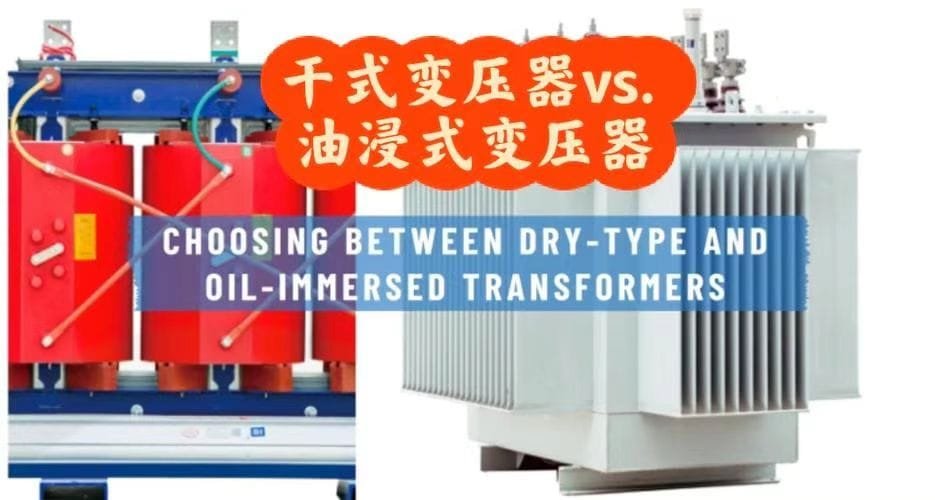
Selecting between oil-immersed and dry-type transformers is one of the most critical early decisions in any power infrastructure project. The wrong choice can lead to operational inefficiency, safety risks, or unnecessary costs over decades of operation. Many project teams base their decision solely on price or footprint, ignoring essential factors such as load duty cycle, environmental conditions, fire safety, cooling method, and maintenance accessibility. The right transformer type should be determined by a holistic evaluation of technical performance, environmental constraints, lifecycle cost, and safety compliance.
In general, oil-immersed transformers are best suited for outdoor, high-power, and utility-grade applications where high efficiency, overload capacity, and long service life are priorities. Dry-type transformers are preferred for indoor, public, or fire-sensitive environments requiring minimal maintenance and enhanced safety. The final selection depends on site conditions, installation environment, load characteristics, and safety regulations.
Selecting the proper type isn’t just about cost—it’s about matching the transformer’s design to your operational risk profile and lifecycle priorities.
Dry-type transformers always outperform oil-immersed units in all environments.False
Dry-type units are safer indoors but have lower efficiency and capacity for high-power outdoor systems. Oil-immersed transformers remain the standard for utility and heavy industrial use.
Oil-immersed transformers require more maintenance than dry-type units.True
Oil-immersed designs need regular oil testing, filtration, and leak inspections, while dry-type transformers require mainly visual and thermal checks.
1. Fundamental Design Differences
| Feature | Oil-Immersed Transformer | Dry-Type Transformer |
|---|---|---|
| Cooling Medium | Mineral or ester insulating oil | Air or epoxy resin encapsulation |
| Core & Winding Protection | Immersed in liquid for insulation and cooling | Encapsulated in resin or varnish |
| Heat Dissipation | Through radiators, fins, or forced oil/air | Through natural or forced air |
| Location | Outdoor or dedicated transformer rooms | Indoor and public access areas |
| Fire Risk | Medium (oil flammable) | Low (self-extinguishing resin) |
| Maintenance Needs | Moderate to high | Low |
| Efficiency | Very high (low losses) | Slightly lower |
| Noise Level | Moderate | Low |
| Size/Weight | More compact for same kVA | Heavier for same kVA |
| Cost | Lower CAPEX for high ratings | Higher CAPEX for high ratings |
Oil-immersed transformers are more energy-efficient and durable, while dry-types are safer and cleaner for enclosed or populated environments.
2. Performance and Efficiency Comparison
Oil-immersed transformers are typically 2–3% more efficient than dry-type units of the same capacity due to better thermal conductivity and lower internal resistance. This difference translates to significant lifetime energy savings in continuous-load systems.
| Parameter | Oil-Immersed | Dry-Type |
|---|---|---|
| Typical Efficiency (at full load) | 99.2–99.6% | 98.8–99.2% |
| Overload Capability | Up to 150% (short-term) | Up to 125% (short-term) |
| Temperature Rise (°C) | 55–65 | 80–120 |
| Service Life (Years) | 30–40 | 20–25 |
| Load Loss Increase (per °C) | Low | High |
Even a 0.3% efficiency difference can equal thousands of dollars per year in energy savings for a large power transformer operating continuously.
Dry-type transformers are more efficient than oil-immersed transformers.False
Oil’s superior heat transfer results in lower winding resistance and smaller load losses, making oil-immersed units generally more efficient.
3. Environmental and Installation Considerations
| Condition | Preferred Type | Reason |
|---|---|---|
| Outdoor installation | Oil-Immersed | Weather-resistant, better cooling |
| Indoor/public area | Dry-Type | No oil leakage, low fire risk |
| Coastal/saline environments | Dry-Type or Ester Oil | Non-corrosive and safer under humidity |
| High altitude (>1000 m) | Oil-Immersed (derated) | Better insulation and cooling margin |
| Hazardous or flammable zones | Dry-Type (cast resin) | Fire-resistant and non-explosive |
| Remote or utility substation | Oil-Immersed | High reliability, longer maintenance interval |
| Hospitals, malls, tunnels, airports | Dry-Type | Safety and ventilation priority |
If fire safety codes (NFPA, IEC 60076-11, or local regulations) prohibit oil-filled equipment indoors, dry-type transformers are mandatory unless installed in fire-rated vaults.
4. Maintenance and Operational Aspects
| Maintenance Task | Oil-Immersed | Dry-Type |
|---|---|---|
| Oil quality test (DGA, acidity, moisture) | Every 1–2 years | Not applicable |
| Visual inspection (leaks, gaskets, corrosion) | 2–4 times/year | 1–2 times/year |
| Filter & purification | Required periodically | None |
| Cooling system check | Fans/pumps | Fans (if forced type) |
| Dust removal | Not needed | Required (monthly in dusty areas) |
| Cleaning interval | 2–3 years | 6–12 months |
| Noise inspection | Required for high-load sites | Lower concern |
Oil-immersed units require more structured maintenance programs, while dry-types can be largely maintenance-free beyond routine inspections.
Dry-type transformers are completely maintenance-free.False
They still need periodic cleaning and thermal inspections, especially in dusty or humid environments.
5. Fire Safety and Environmental Protection
Fire and environmental regulations are key decision drivers.
Oil-Immersed Transformers
- Risk: Oil leakage, fire potential, contamination
- Mitigation: Fire barriers, containment pits, ester oil alternatives
- Standards: IEC 60076, IEEE C57.12, NFPA 30
- New trend: Natural ester (FR3)—biodegradable, high flash point (>300°C)
Dry-Type Transformers
- Risk: Minimal; resin self-extinguishing
- Ideal for: Public buildings, tunnels, basements
- Compliance: IEC 60076-11, UL1562, NFPA 70
| Fire Parameter | Oil-Immersed (Mineral) | Ester Oil (Natural) | Dry-Type (Epoxy) |
|---|---|---|---|
| Flash Point (°C) | 150–160 | 300–330 | Non-flammable |
| Fire Class | Class II (flammable) | Class K3 (fire-safe) | Class F1 (self-extinguishing) |
| Spill Containment | Required | Recommended | Not required |
| Environmental Risk | Medium | Low | Very Low |
Ester oils bridge the gap—offering oil performance with near-dry safety.
6. Typical Applications by Industry
| Application | Recommended Type | Rationale |
|---|---|---|
| Utility substation (≥5 MVA) | Oil-Immersed | Highest efficiency, proven durability |
| Renewable energy (wind/solar step-up) | Oil-Immersed (ester oil optional) | Handles outdoor, fluctuating loads |
| Industrial plant (indoor section) | Dry-Type | Safer for personnel and confined areas |
| Data centers | Dry-Type (cast resin) | Low fire risk, clean environment |
| Mines & tunnels | Dry-Type | Explosion-proof, moisture-resistant |
| Residential/commercial buildings | Dry-Type | Compact and low-maintenance |
| Marine/offshore platforms | Ester Oil-Immersed | Fire-safe and resistant to humidity |
| Critical hospital or airport substations | Ester Oil-Immersed or Dry-Type | Safety + reliability balance |
Ester oil-immersed transformers combine efficiency with enhanced fire safety.True
Natural ester fluids are biodegradable, have higher flash points, and offer both efficiency and environmental compliance.
7. Cost Comparison (CAPEX + OPEX)
| Cost Element | Oil-Immersed | Dry-Type |
|---|---|---|
| Initial CAPEX | Lower (–10 to –25%) | Higher (+15–30%) |
| Installation | Moderate (requires oil handling) | Lower (simple indoor setup) |
| Maintenance | Higher (oil tests, filtration) | Lower (cleaning only) |
| Energy Losses (OPEX) | Lower | Slightly higher |
| Service Life | Longer (30–40 yrs) | Shorter (20–25 yrs) |
| Environmental / Fire Safety Cost | Medium | Low |
| Total Lifecycle Cost | Lower for outdoor/utility | Lower for indoor/public |
In lifecycle terms, oil-immersed transformers often provide 15–20% lower TCO in high-duty outdoor installations, while dry-types minimize cost and risk indoors.
8. Technical Performance Summary Chart
| Criterion | Oil-Immersed | Dry-Type | Best Choice |
|---|---|---|---|
| Efficiency | ★★★★★ | ★★★★☆ | Oil |
| Fire Safety | ★★☆☆☆ | ★★★★★ | Dry |
| Maintenance | ★★★☆☆ | ★★★★★ | Dry |
| Environmental Safety | ★★★☆☆ | ★★★★★ | Dry |
| Lifespan | ★★★★★ | ★★★★☆ | Oil |
| Noise | ★★★★☆ | ★★★★★ | Dry |
| Cost Effectiveness | ★★★★★ | ★★★☆☆ | Oil |
| Indoor Suitability | ★★☆☆☆ | ★★★★★ | Dry |
| Outdoor Suitability | ★★★★★ | ★★★☆☆ | Oil |
9. Decision Framework (Expert Selection Flow)
- Is the transformer installed indoors or near personnel?
→ Choose Dry-Type (or Ester Oil if efficiency is critical). - Is the rating above 2.5 MVA or continuous high load?
→ Choose Oil-Immersed. - Is fire/environmental risk a top priority?
→ Choose Dry-Type or Ester Oil. - Is low maintenance your goal?
→ Dry-Type. - Is efficiency and overload resilience your priority?
→ Oil-Immersed.
This method ensures your choice aligns with technical, financial, and regulatory priorities.
What Voltage Levels and Capacity Are Required for a Power Transformer?
In any power distribution or industrial project, one of the earliest yet most critical design decisions is determining the correct voltage level and transformer capacity. Selecting these parameters incorrectly can lead to system inefficiencies, overloading, power loss, or costly downtime. Many project teams underestimate how load diversity, distance, and network configuration impact transformer ratings, often leading to either oversized (wasteful) or undersized (risk-prone) systems. The solution is a precise technical assessment based on load profile, demand forecast, system voltage hierarchy, and operational flexibility.
In short, the required voltage level and capacity of a power transformer depend on the system voltage (e.g., 11 kV, 33 kV, 66 kV, 110 kV, 220 kV), load demand in kVA or MVA, load factor, and the configuration of the distribution or transmission network. Accurate selection ensures optimal performance, energy efficiency, and reliability without unnecessary capital cost.
A transformer’s voltage and capacity must match both the grid and the load, serving as the electrical bridge that ensures stable, efficient, and safe power flow.
Transformer voltage level should always match the system voltage exactly.False
Transformers are designed with standardized voltage ratios that accommodate tap settings to match variations in system voltage.
Oversizing a transformer always improves reliability.False
Oversizing reduces efficiency at partial loads and increases initial cost, contrary to optimal design practice.
1. Understanding System Voltage Levels
Voltage levels define how electricity is transmitted and distributed from generation to consumption. Standard system voltages vary globally but follow similar hierarchical patterns.
| Voltage Category | Typical Range (kV) | Common Applications | Transformer Type |
|---|---|---|---|
| Low Voltage (LV) | 0.4 – 1 | Local distribution to loads | LV distribution transformers |
| Medium Voltage (MV) | 3.3 – 33 | Industrial networks, feeders | Step-up/step-down transformers |
| High Voltage (HV) | 66 – 220 | Regional transmission | Power transformers |
| Extra-High Voltage (EHV) | 230 – 765 | Inter-regional transmission | Bulk power transformers |
| Ultra-High Voltage (UHV) | ≥ 800 | National or long-distance lines | Grid interconnect transformers |
Each voltage level corresponds to a stage in the power system hierarchy. The transformer must step voltage up or down appropriately between these tiers.
A 33/0.4 kV transformer can operate on a 66 kV grid.False
A 33/0.4 kV transformer cannot handle 66 kV input; it must be matched or replaced with a 66/0.4 kV unit or step-down cascade.
2. Capacity Determination — The Core Formula
Transformer capacity is usually expressed in kVA or MVA, depending on application scale.
The base formula to determine required capacity is:
[S (kVA) = \frac{P(kW)}{PF}]
Where:
- P = Total load power in kW
- PF = Power factor (typically 0.8–0.95)
Example:
For a total load of 3200 kW with a PF of 0.9,
S = 3200 / 0.9 = 3555 kVA (≈3.56 MVA) transformer required.
However, other factors—diversity factor, future expansion, and load type (continuous or intermittent)—must also be considered.
| Design Factor | Typical Value | Effect on Capacity |
|---|---|---|
| Load Factor | 0.7–0.8 | Determines average usage over time |
| Demand Factor | 0.6–0.9 | Reflects peak demand ratio |
| Diversity Factor | 1.1–1.3 | Reduces total capacity for diversified loads |
| Future Expansion Margin | 10–25% | Adds flexibility for future growth |
Thus, total required capacity = Peak Load × Diversity Factor × Expansion Margin.
The kVA rating of a transformer depends only on the connected load.False
It also depends on load factor, diversity, power factor, and potential expansion needs.
3. Typical Transformer Ratings by Application
| Application | Voltage Level | Capacity Range (kVA/MVA) | Type |
|---|---|---|---|
| Residential Block | 11/0.4 kV | 200 – 1000 kVA | Distribution |
| Industrial Plant | 33/0.4 kV | 1000 – 5000 kVA | Power |
| Wind Farm Collector | 33/132 kV | 10 – 50 MVA | Step-up |
| Transmission Substation | 220/66 kV | 50 – 200 MVA | Power |
| Metro/Rail Substation | 132/33 kV | 20 – 120 MVA | Traction |
| Data Center | 11/0.4 kV | 1000 – 4000 kVA | Dry-type or oil-immersed |
| Utility Interconnection | 500/230 kV | 300 – 800 MVA | EHV Transformer |
These ranges serve as baseline guidance but must be validated through load flow analysis and grid code compliance.
4. Voltage Ratio Selection and Tap Changer Role
Transformers are designed with standard primary/secondary voltage ratios and equipped with tap changers to fine-tune voltage regulation.
| Feature | On-Load Tap Changer (OLTC) | Off-Circuit Tap Changer (OCTC) |
|---|---|---|
| Regulation Range | ±10% (1.25% steps typical) | ±5% (2.5% steps typical) |
| Control Mode | Automatic during operation | Manual, offline |
| Application | Grid and transmission | Distribution and local use |
| Impact on Price | +10–15% higher | Base price |
For voltage-sensitive systems, especially industrial grids and renewables, OLTC-equipped transformers ensure stable performance under variable conditions.
Tap changers can only adjust voltage by ±2%.False
Modern OLTC systems can regulate up to ±10% with fine incremental steps.
5. Load Profile and Demand Forecasting
Determining voltage and capacity accurately requires understanding load characteristics over time.
Engineers typically analyze:
| Load Type | Characteristics | Example Applications |
|---|---|---|
| Continuous Load | Constant power draw | HVAC, lighting, data centers |
| Intermittent Load | Fluctuating demand | Machinery, cranes |
| Seasonal Load | Peaks in certain months | Agriculture, cooling plants |
| Emergency Load | Backup or standby | Hospitals, telecom stations |
A 24-hour load curve provides insights into peak load and base load behavior:
| Time (hr) | Load (%) | Remarks |
|---|---|---|
| 0–6 | 45–60 | Base load (night) |
| 6–12 | 70–90 | Morning ramp-up |
| 12–18 | 100 | Peak |
| 18–24 | 60–80 | Evening decline |
The average-to-peak ratio determines the load factor, influencing transformer efficiency and selection size.
6. Impact of Voltage on Efficiency and Losses
Transformer losses are divided into core losses (no-load) and copper losses (load-dependent).
Voltage affects both insulation design and current magnitude.
| Voltage Level (kV) | Current (A) at 5 MVA Load | Copper Loss Impact |
|---|---|---|
| 11 | 262 | High (more I²R loss) |
| 33 | 87 | Medium |
| 66 | 44 | Low |
| 132 | 22 | Very Low |
Higher voltages reduce current and hence power loss, improving system efficiency.
However, higher voltage systems increase insulation cost and clearance space.
Raising the transformer voltage always reduces total system cost.False
Higher voltage reduces current losses but increases insulation, protection, and substation equipment costs.
7. Safety, Standards, and Derating
Transformers must conform to IEC 60076, IEEE C57, or GB/T 6451 standards.
At high altitudes (>1000 m) or high ambient temperatures (>40°C), capacity derating is mandatory.
| Condition | Correction Factor | Reason |
|---|---|---|
| Altitude > 1000 m | –1% per 100 m | Reduced cooling air density |
| Ambient Temp 45°C | –5% | Reduced cooling efficiency |
| Humidity > 95% | Special insulation | Moisture risk |
| Harmonic Loads | Oversize by 10–15% | Extra heating in windings |
These corrections ensure transformer reliability in non-standard environments.
8. Case Study: 10 MVA Industrial Power Substation
Project Conditions:
- Industrial plant, 24/7 load
- Peak demand: 8 MW
- PF: 0.9
- Grid voltage: 33 kV
- Load voltage: 0.4 kV
Calculation:
S = 8000 / 0.9 = 8.89 MVA
Add 15% expansion → 10.2 MVA
Result: Recommended transformer:
- Rating: 33/0.4 kV, 10 MVA
- Cooling: ONAN/ONAF
- Tap Range: ±10% OLTC
- Impedance: 8%
- Efficiency: 99.3%
Outcome: Optimal cost-performance ratio with no overload risk and high efficiency under 0.8–1.0 PF load range.
9. Practical Engineering Tips
- Always base transformer sizing on maximum apparent power (kVA), not just kW.
- Consider future load expansion and network reconfiguration potential.
- For renewable or variable load projects, oversize by 10–15% to accommodate fluctuations.
- In urban or confined installations, lower voltage and compact dry-type may be advantageous.
- Validate design with load flow simulation using ETAP or DIgSILENT PowerFactory.
How Do Site and Environmental Conditions Influence Power Transformer Selection?
Environmental and site conditions are among the most decisive factors influencing power transformer design, performance, and longevity. Yet, these factors are often underestimated during the early procurement phase, leading to serious issues such as premature insulation aging, overheating, corrosion, or dielectric breakdown. Transformers are not plug-and-play components; they are engineered systems whose operation depends heavily on the ambient temperature, altitude, humidity, pollution level, seismic activity, and installation environment. Failure to adapt the design to site-specific conditions can shorten the transformer’s lifespan and significantly increase maintenance costs.
In short, site and environmental conditions directly determine a power transformer’s insulation design, cooling method, material selection, protection level, and enclosure type. Factors such as temperature, humidity, altitude, contamination, seismic risk, and installation environment (indoor/outdoor) affect how the transformer is specified, tested, and rated to ensure safe and reliable operation over its service life.
These parameters are not optional—they define the boundary conditions under which your transformer must safely perform for decades.
All transformers can be installed in any environment without modification.False
Transformers require customization of insulation, cooling, and enclosure to match environmental stresses such as temperature, humidity, or pollution level.
Environmental factors have minimal effect on transformer performance.False
Conditions like heat, altitude, and humidity significantly impact insulation, cooling, and lifetime reliability.
1. Temperature and Ambient Conditions
Temperature is one of the primary environmental influencers on transformer performance. High ambient temperatures accelerate insulation degradation and reduce cooling efficiency.
| Condition | Standard Rating (IEC 60076) | Impact | Required Adaptation |
|---|---|---|---|
| Ambient ≤ 40°C | Standard design | Normal operation | None |
| Ambient 45–50°C | Tropical or desert | Overheating risk | Oversized radiators, forced cooling |
| Ambient > 50°C | Extreme | Thermal stress | Special insulation, oil pumps/fans |
| Sub-zero (<–25°C) | Arctic or mountain | Oil viscosity increase | Low-temperature oil, heaters |
| Rapid variation (>15°C/day) | Coastal | Thermal cycling | Flexible bushings and seals |
For every 10°C rise above standard operating temperature, the insulation life reduces by approximately 50%, as per Arrhenius’ thermal aging law.
| Parameter | Standard (°C) | Adjusted (for high ambient) |
|---|---|---|
| Hot-spot Temperature | 98 | 110 |
| Top Oil Temperature | 85 | 95 |
| Winding Rise | 65 | 75 |
Hence, temperature dictates cooling type selection (ONAN, ONAF, OFAF, or OFWF) and determines whether to include temperature sensors or automatic fan control.
Temperature variations have little effect on transformer insulation.False
Excess heat accelerates insulation aging exponentially, halving transformer life with every 10°C increase.
2. Altitude and Air Density
At higher altitudes, air pressure and density decrease, reducing the cooling capability and dielectric strength of air insulation. Transformers must be derated above 1000 m elevation.
| Altitude (m) | Cooling Correction Factor | Voltage Withstand Derating |
|---|---|---|
| 0–1000 | 1.00 | 100% |
| 1500 | 0.97 | 95% |
| 2000 | 0.95 | 92% |
| 3000 | 0.90 | 88% |
| 4000 | 0.85 | 84% |
At high altitude sites such as hydropower plants or mountain substations, transformers are equipped with:
- Enhanced oil circulation systems
- Upgraded bushing insulation
- Sealed-tank construction to prevent moisture ingress
IEC 60076-2 specifies derating curves for both temperature rise and insulation coordination in such conditions.
3. Humidity and Moisture Exposure
Moisture is a hidden enemy of transformers—it reduces insulation resistance, accelerates partial discharge, and promotes corrosion.
| Humidity Level (%) | Environment Type | Recommended Design Feature |
|---|---|---|
| <70 | Normal | Standard insulation |
| 70–90 | Humid | Sealed tank, silica gel breathers |
| >90 | Tropical/Coastal | Hermetically sealed, nitrogen cushion |
| Condensing (rain/dust) | Outdoor coastal | IP55/IP65 enclosures |
For dry-type transformers, high humidity can cause surface tracking and dielectric breakdown. Thus, cast-resin or vacuum-pressure encapsulated (VPI) units are preferred in such climates.
Moisture does not affect transformer insulation.False
Moisture in paper insulation reduces dielectric strength and accelerates aging and partial discharge.
4. Pollution, Dust, and Corrosive Atmosphere
Industrial or coastal environments often contain corrosive gases (SO₂, Cl₂) or salt mist, which degrade metal components and cause surface flashover on bushings and insulators.
| Pollution Level (IEC 60815) | Typical Environment | Required Insulation Creepage (mm/kV) |
|---|---|---|
| I (Light) | Rural, clean air | 16 |
| II (Medium) | Suburban | 20 |
| III (Heavy) | Industrial, coastal | 25 |
| IV (Very Heavy) | Desert, cement plant, smelter | 31 |
Mitigation measures include:
- Porcelain bushings with longer creepage distance
- Silicone rubber insulators for self-cleaning
- Anti-corrosive paint coatings (C3–C5 grade)
- IP55/IP65 rated enclosures
Transformers in desert regions often require sand filters and forced ventilation systems with dust-proof barriers.
5. Seismic and Structural Conditions
In earthquake-prone zones, transformers must meet seismic withstand standards (IEEE 693, IEC 60068).
Mechanical reinforcement is critical to prevent tank deformation or bushing breakage.
| Seismic Zone (PGA in g) | Region Example | Design Enhancement |
|---|---|---|
| <0.1 (Low) | Europe, parts of Africa | Standard base |
| 0.1–0.3 (Medium) | Turkey, China, USA (CA) | Reinforced base, flexible connectors |
| 0.3–0.5 (High) | Japan, Chile, Indonesia | Shock absorbers, seismic isolators |
| >0.5 (Extreme) | Himalayas, Andes | Seismic foundation isolation |
Special mounting brackets and anti-vibration bushings are added to maintain electrical and mechanical integrity during seismic events.
6. Indoor vs Outdoor Installation
| Installation Type | Typical Environment | Transformer Design Recommendation |
|---|---|---|
| Indoor (substation, building) | Controlled, low dust | Dry-type or ester oil, IP23/IP31 |
| Outdoor (utility yard) | Exposed to weather | Oil-immersed, IP55/IP65, canopy |
| Underground | Limited ventilation | Sealed tank, forced cooling |
| Offshore / Marine | High humidity and salt | Stainless steel tank, C5 anti-corrosion |
For indoor safety, dry-type transformers are preferred due to fire resistance and absence of oil leakage risk.
Outdoor units require weather-proofing, breathers, and oil containment pits.
Outdoor transformers do not require any weather protection.False
Outdoor transformers must include IP-rated enclosures, paint protection, and oil containment systems to withstand environmental exposure.
7. Cooling System Adaptation
Cooling design is crucial to maintain transformer temperature within limits under specific site conditions.
The following summarizes the cooling methods relative to environmental challenges:
| Cooling Type | Description | Recommended Use |
|---|---|---|
| ONAN | Natural air circulation | Mild climate, ≤40°C |
| ONAF | Forced air | Hot climate or continuous high load |
| OFAF | Forced oil + air | High capacity units, ≥30 MVA |
| OFWF | Oil-water | Space-limited or indoor applications |
| AN/AF (Dry-Type) | Natural or forced air | Indoor, clean environment |
Selecting the correct cooling mode ensures efficient operation and prevents overheating in extreme climates.
8. Environmental Compliance and Fluid Choice
Oil-immersed transformers traditionally use mineral oil, but eco-friendly alternatives are gaining popularity due to environmental and fire safety regulations.
| Insulating Fluid | Flash Point (°C) | Biodegradability (%) | Recommended Environment |
|---|---|---|---|
| Mineral Oil | 155 | <10 | Outdoor, standard |
| Synthetic Ester | 260 | 90 | Urban, indoor |
| Natural Ester (FR3) | 320 | 99 | Eco-sensitive areas |
| Silicone Oil | 300 | 90 | Tunnel, offshore |
Natural ester fluids are now widely used in hospitals, tunnels, and data centers, providing both fire safety and environmental compliance.
Natural ester oils are less fire-safe than mineral oils.False
Natural esters have a higher flash point and self-extinguishing properties, making them safer than mineral oils.
9. Comprehensive Environmental Adaptation Matrix
| Environmental Factor | Effect on Transformer | Design/Material Solution |
|---|---|---|
| High Temperature | Accelerated insulation aging | Oversized cooling, high-temp insulation |
| High Humidity | Dielectric degradation | Sealed tank, nitrogen protection |
| Dust & Pollution | Surface tracking | Silicone insulators, IP55 housing |
| Altitude | Lower cooling efficiency | Derating, forced cooling |
| Seismic Risk | Structural failure | Reinforced frame, flexible bushings |
| Corrosive Air | Metal corrosion | C5 paint, stainless steel fittings |
| Fire Hazard | Oil ignition risk | Ester oil, dry-type design |
| Environmental Sensitivity | Contamination risk | Biodegradable fluids, containment pits |
10. Case Example: Coastal Industrial Substation
Site: Coastal chemical plant, ambient 45°C, humidity >90%, saline air
Challenge: Corrosion, insulation degradation, and high ambient temperature
Solution:
- Type: 33/11 kV, 20 MVA transformer
- Design: Sealed tank, stainless radiator fins, ester oil cooling
- Features: OLTC ±10%, IP55 rating, forced cooling (ONAF)
Result: 25-year projected service life with 30% reduction in maintenance frequency and improved dielectric reliability.
What Standards, Efficiency Ratings, and Safety Requirements Apply to Power Transformers?
Power transformers are among the most critical and expensive components in the electrical power system. Yet, one of the most underestimated aspects in their procurement is ensuring compliance with international standards, efficiency classifications, and safety certifications. A transformer that is not certified or built according to recognized standards may initially appear cost-effective but could lead to catastrophic failures, high operational losses, or even non-approval by local utility regulators. In a globalized energy market, where performance and reliability are paramount, adherence to proper standards and efficiency regulations is not optional—it is the foundation of safe, efficient, and sustainable power operation.
In essence, power transformers must comply with established international standards such as IEC 60076, IEEE C57, and ISO/IEC 17025 for testing; meet regulated efficiency classes such as DOE, EU Ecodesign, or BIS star ratings; and fulfill safety and environmental requirements related to dielectric insulation, temperature rise, short-circuit withstand, fire protection, and eco-design. These frameworks ensure operational reliability, electrical safety, reduced energy losses, and legal conformity across global markets.
Transformers that adhere to these benchmarks not only deliver long-term performance stability but also significantly reduce lifecycle costs and environmental impact.
All transformers perform equally regardless of standards compliance.False
Non-standard transformers may not meet dielectric, temperature rise, or efficiency benchmarks, leading to reduced reliability and lifespan.
Efficiency classes are voluntary and have minimal impact on transformer operation.False
Efficiency classes determine allowable energy losses and directly affect operational cost and grid performance.
1. International Standards Governing Power Transformers
Transformers are designed, manufactured, and tested in compliance with globally recognized standards that define their electrical, mechanical, and thermal properties. The most dominant standard systems are IEC (International Electrotechnical Commission) and IEEE/ANSI (Institute of Electrical and Electronics Engineers/American National Standards Institute).
| Standard Organization | Standard Number | Scope | Key Coverage Areas |
|---|---|---|---|
| IEC | 60076 Series | General and special transformers | Design, testing, insulation, cooling, efficiency |
| IEEE/ANSI | C57 Series | North American transformers | Construction, testing, load tap changers |
| ISO | 9001 / 14001 / 45001 | Quality, environment, safety management | Factory and process certification |
| ASTM | D3487 / D6871 | Transformer oil and fluid standards | Dielectric strength, fire safety |
| EN (European Norms) | 50588 / 50464 | Ecodesign and loss limits | Efficiency requirements (Tier 1, Tier 2) |
| BIS (India) | IS 1180 / IS 2026 | Distribution & power transformers | Star-rated efficiency, testing |
| GB (China) | GB 1094 | National power transformer standards | Equivalent to IEC 60076 |
IEC and IEEE standards are interchangeable without adaptation.False
IEC and IEEE standards differ in insulation coordination, test voltage levels, and design assumptions; transformers must match their target market's standards.
IEC 60076 is the global benchmark for most international projects, whereas IEEE C57 applies primarily to North American grids. The choice of standard depends on project location, grid code, and utility specification.
2. Efficiency Ratings and Energy Performance Regulations
Transformer efficiency is not a simple technical feature—it is a regulatory requirement enforced by energy agencies worldwide. Transformer losses are categorized into:
- No-load (core) losses: Constant, even without load
- Load (copper) losses: Proportional to current flow
IEC and EU Ecodesign Efficiency Classes
| Class | Applicable Standard | Implementation Date | Typical Efficiency (Distribution Transformer) |
|---|---|---|---|
| Tier 1 | EU 548/2014 | 2015 | 99.4% |
| Tier 2 | EU 2019/1783 | 2021 | 99.6% |
| Tier 3 (Proposed) | 2027 | 99.7%+ |
US DOE 2016 Rule (10 CFR Part 431)
| Transformer Type | Capacity Range | Minimum Efficiency |
|---|---|---|
| Low-voltage dry-type | 15–2500 kVA | 98.5–99.4% |
| Medium-voltage liquid-immersed | 10–2500 kVA | 99.2–99.6% |
India (BIS Star Rating)
| Star Rating | Efficiency Level at 50% Load (11/0.433 kV) |
|---|---|
| 3 Star | 98.28% |
| 4 Star | 98.52% |
| 5 Star | 98.75% |
Energy-efficient transformers are typically amorphous core or CRGO-based designs that significantly reduce no-load losses.
An additional cost of 5–10% at purchase may result in lifetime savings of over 20–30% in energy losses.
3. Safety Standards and Design Requirements
Transformer safety is governed by multiple criteria ensuring personnel, equipment, and environmental protection.
| Safety Aspect | Applicable Standard/Requirement | Key Technical Measure |
|---|---|---|
| Electrical Safety | IEC 60076-3, IEEE C57.12.90 | Dielectric tests (AC, impulse, PD) |
| Thermal Safety | IEC 60076-2 | Temperature rise limits |
| Short-Circuit Strength | IEC 60076-5 | Mechanical withstand verification |
| Fire Safety | IEC 60076-14, NFPA 850 | Flame-retardant fluids, containment |
| Environmental Safety | IEC 61039, ISO 14001 | Oil handling, spill control |
| Noise Emission | IEC 60076-10 | Sound level measurement and limits |
For fire-prone or sensitive areas (e.g., data centers, tunnels), natural ester oil or dry-type cast resin units are required due to their high flash point and self-extinguishing behavior.
| Fluid Type | Flash Point (°C) | Fire Risk Level | Standard Reference |
|---|---|---|---|
| Mineral Oil | 155 | High | IEC 60296 |
| Synthetic Ester | 260 | Low | IEC 61099 |
| Natural Ester (FR3) | 320 | Very Low | IEC 62770 |
| Silicone Oil | 300 | Very Low | IEC 60836 |
Mineral oil transformers are always safe for indoor applications.False
Mineral oil has a lower flash point and higher fire risk, making ester or dry-type transformers preferred for indoor or urban sites.
4. Testing and Certification Requirements
Compliance is validated through rigorous factory testing per IEC 60076-1 (Routine and Type Tests) and additional special tests for specific projects.
| Test Type | Purpose | Typical Standard |
|---|---|---|
| Routine Test | Factory acceptance | IEC 60076-1 |
| Type Test | Design validation | IEC 60076-3, 60076-5 |
| Special Test | Project-specific | IEC 60076-10, 60076-18 |
| Dielectric Test | Insulation verification | Lightning impulse, switching surge |
| Temperature Rise Test | Thermal behavior check | IEC 60076-2 |
| Noise Test | Acoustic limit verification | IEC 60076-10 |
| Short-Circuit Test | Mechanical robustness | IEC 60076-5 |
| Partial Discharge | Insulation health | IEC 60270 |
Testing is typically performed in ISO/IEC 17025 accredited laboratories, ensuring data traceability and third-party certification.
5. Environmental and Eco-Design Compliance
Sustainability standards now require transformers to minimize losses, emissions, and oil leakage risks.
| Regulatory Framework | Key Requirements | Impact on Design |
|---|---|---|
| EU Ecodesign Directive | Tier 1–2 loss limits | Amorphous core, optimized windings |
| ISO 14001 | Environmental management | Certified manufacturing |
| RoHS / REACH | Restriction of hazardous substances | Lead-free paint, eco-friendly oil |
| IEC 62770 | Biodegradable natural ester fluids | Green transformer development |
| NFPA 850 | Fire protection for substations | Bund walls, ester fluids |
| IEEE 979 | Oil spill containment | Secondary containment pits |
These standards promote eco-transformers that reduce environmental footprint and comply with net-zero energy transition goals.
Transformer design has no impact on environmental compliance.False
Material selection, fluid type, and loss level directly influence environmental impact and regulatory approval.
6. Comparison of Global Compliance Frameworks
| Region | Primary Standards | Efficiency Scheme | Safety & Environment Focus |
|---|---|---|---|
| Europe | IEC 60076, EN 50588 | EU Ecodesign Tier 1/2 | Noise, losses, eco-materials |
| North America | IEEE C57 | DOE 2016 | Fire safety, short-circuit strength |
| Asia-Pacific | IEC/GB/IS | BIS Star Rating | Energy conservation, reliability |
| Middle East | IEC 60076 | Utility-specific (DEWA, SEC) | Desert temperature, dust |
| Africa | IEC 60076 | National adoption | Durability, cost efficiency |
Such harmonized compliance enables international project compatibility and simplifies tender evaluation across markets.
7. Efficiency and Loss Evaluation Table
| Transformer Rating (MVA) | No-Load Loss (kW) | Load Loss (kW) | Efficiency (%) @ Full Load |
|---|---|---|---|
| 5 MVA | 5.5 | 35 | 99.47 |
| 10 MVA | 8 | 60 | 99.52 |
| 20 MVA | 12 | 110 | 99.57 |
| 50 MVA | 25 | 250 | 99.62 |
| 100 MVA | 45 | 450 | 99.67 |
Each incremental efficiency gain significantly reduces operational costs over a 25–30 year life cycle.
8. Real-World Example: IEC-Compliant Transformer Project
Project: 132/33 kV, 63 MVA Oil-Immersed Transformer for Utility Grid
Standards Applied: IEC 60076 Series, IEC 60296 (oil), IEC 60076-5 (short-circuit)
Efficiency Class: EU Ecodesign Tier 2
Safety Design: Natural ester oil, C5 anti-corrosive coating, noise <65 dB
Certification: ISO 9001/14001/45001 & IEC Type Test (KEMA-certified)
Result: 0.25% lower total loss and 28-year operational reliability with minimal maintenance.
How Do Budget, Maintenance, and Lifecycle Costs Affect the Final Decision When Choosing a Power Transformer?
Selecting a power transformer is not just about its purchase price. It’s a long-term financial and technical decision that affects the total cost of ownership, operational reliability, and even environmental impact for decades. Many projects focus solely on upfront capital expenditure (CAPEX), overlooking ongoing maintenance, energy losses, and end-of-life expenses. This narrow focus often leads to higher total lifecycle costs, unexpected downtime, and reduced return on investment (ROI). Understanding the interplay between budget constraints, maintenance needs, and lifecycle economics is critical to making a cost-effective and technically sound decision.
In short, the total cost of owning a power transformer is determined not only by its purchase price but also by maintenance frequency, energy loss costs, efficiency class, expected service life, and environmental compliance. A balanced decision should compare both CAPEX and OPEX (operational expenditure), optimizing for lowest lifetime cost rather than lowest initial price.
This perspective helps utilities, industries, and EPC contractors avoid false economies and ensures long-term reliability and regulatory compliance.
The lowest purchase price always means the most economical transformer.False
A cheaper transformer with higher losses or poor efficiency can cost more in energy and maintenance over its lifetime.
Maintenance and efficiency have minor influence on transformer economics.False
Energy losses and maintenance make up the majority of a transformer's total lifecycle cost, far exceeding the purchase price.
1. Understanding the Three Cost Dimensions: CAPEX, OPEX, and Lifecycle
Every transformer investment can be evaluated under three primary financial pillars:
| Cost Category | Description | Examples | Impact on Project |
|---|---|---|---|
| CAPEX (Capital Expenditure) | One-time cost to purchase and install the transformer | Manufacturing, shipping, installation | 20–30% of total cost |
| OPEX (Operational Expenditure) | Recurring annual costs during operation | Energy losses, oil changes, inspections | 60–70% of total cost |
| Lifecycle/Decommissioning Cost | End-of-life, disposal, recycling | Oil treatment, metal recycling | 5–10% of total cost |
For high-voltage transformers, OPEX (especially energy losses) dominates the total cost equation. Over a 25-year service life, losses can cost 5–8 times the initial price of the transformer.
2. Cost Contribution Breakdown Over the Transformer’s Life
| Cost Component | Typical Share (%) | Explanation |
|---|---|---|
| Purchase Price | 20 | Transformer, transport, installation |
| No-Load Losses | 35 | Energy wasted even at zero load |
| Load Losses | 25 | Heat generation under load |
| Maintenance | 10 | Oil analysis, gasket replacement, testing |
| Downtime / Failure | 5 | Production loss, repair |
| End-of-Life Disposal | 5 | Dismantling, recycling, waste oil management |
Thus, reducing energy losses by even 0.1% can produce significant lifetime savings, especially in industrial or utility-scale applications.
Transformer losses are negligible compared to purchase price.False
Operational energy losses can exceed initial capital cost several times during a 25-year lifecycle.
3. Maintenance Strategy and Its Financial Impact
Maintenance practices directly affect a transformer’s operational reliability, efficiency, and cost curve. Transformers that are properly maintained last up to 30–40 years, while neglected units can fail within 10–15 years.
| Maintenance Type | Interval | Typical Cost (USD/year) | Purpose |
|---|---|---|---|
| Routine Inspection | Quarterly | 200–400 | Detect oil leaks, noise, temperature changes |
| Oil Testing & Filtering | Annual | 800–1500 | Check dielectric strength, moisture, acidity |
| Thermal Imaging | Biennial | 500–700 | Identify hotspot or winding issues |
| Bushing & Tap Changer Service | 5 years | 3000–5000 | Prevent contact wear and arcing |
| Overhaul / Refurbishment | 15–20 years | 20,000–50,000 | Extend operational life |
Maintenance costs are modest compared to potential downtime losses. A transformer failure at a manufacturing plant can cause production losses of $50,000–100,000 per hour.
| Maintenance Level | Expected Life (Years) | Failure Probability (%) |
|---|---|---|
| Preventive | 30–35 | <3 |
| Reactive | 15–20 | 15 |
| None | <10 | >30 |
4. Energy Efficiency and Loss Cost Analysis
Transformer efficiency directly translates to electricity cost over decades.
Let’s assume electricity costs $0.12/kWh, and a 10 MVA transformer operates at 70% load for 25 years:
| Transformer Type | Efficiency (%) | Total Energy Loss (MWh) | Lifetime Loss Cost (USD) |
|---|---|---|---|
| Standard (Tier 1) | 99.45 | 28,700 | 3,444,000 |
| High Efficiency (Tier 2) | 99.60 | 20,900 | 2,508,000 |
| Premium (Amorphous Core) | 99.70 | 15,700 | 1,884,000 |
By choosing a higher efficiency transformer (Tier 2 or amorphous core), you can save over $1.5 million in loss cost across its lifecycle — far exceeding the initial price difference.
Energy efficiency improvements offer minimal financial benefit.False
Even small improvements in transformer efficiency produce significant savings in energy cost over decades of operation.
5. Lifecycle Cost (LCC) Evaluation Formula
The total ownership cost (TOC) or lifecycle cost (LCC) is calculated using:
[LCC = Ci + \sum{n=1}^{N} \frac{(A + L + M)}{(1 + r)^n}]
Where:
- Cᵢ = Initial purchase cost
- A = Annual no-load loss cost
- L = Annual load loss cost
- M = Annual maintenance cost
- r = Discount rate
- N = Transformer lifespan (years)
This formula is used in IEC 60076-20 and IEEE C57.120 for economic evaluation.
A graphical comparison is shown below:
| Transformer Type | Initial Cost (USD) | Annual Loss Cost (USD) | Maintenance (USD) | 25-Year LCC (USD) |
|---|---|---|---|---|
| Standard | 250,000 | 130,000 | 3,000 | 3,530,000 |
| High Efficiency | 280,000 | 95,000 | 3,000 | 2,705,000 |
| Premium | 320,000 | 75,000 | 3,000 | 2,295,000 |
Even though premium designs have higher CAPEX, they achieve 35% lower lifetime cost.
6. Downtime and Reliability Cost Considerations
Unexpected transformer failures can impose massive unplanned costs beyond repair expenses. Downtime affects productivity, safety, and brand reputation.
| Industry | Typical Loss per Hour (USD) | Root Causes of Failure |
|---|---|---|
| Manufacturing | 50,000–100,000 | Overheating, poor oil quality |
| Data Centers | 200,000–400,000 | Dielectric failure, load surge |
| Utilities | 10,000–25,000 | Aging insulation, moisture |
| Mining / Oil & Gas | 80,000–200,000 | Overload, vibration, contamination |
Thus, a transformer with higher reliability and better monitoring systems (e.g., DGA sensors, online oil monitoring) can save millions in avoided outages.
Transformer downtime has little financial consequence.False
Outages can result in production and service losses that far exceed the cost of preventive maintenance.
7. Cost-Benefit Analysis of Monitoring Systems
Adding smart monitoring or digital sensors slightly increases CAPEX but substantially lowers lifecycle cost.
| System Type | Added Cost (USD) | Benefit | Payback (Years) |
|---|---|---|---|
| DGA Online Monitor | 8,000 | Detects insulation degradation early | 2–3 |
| Temperature & Load Sensors | 4,000 | Prevents overload and hotspot failures | 1–2 |
| Smart Tap Changer Controller | 5,000 | Reduces switching wear, extends life | 2–4 |
Such technologies enable predictive maintenance, improving availability by >98%.
8. Environmental and End-of-Life Costs
At the end of its service life, transformer disposal includes oil recovery, copper/aluminum recycling, and tank dismantling. Using eco-friendly materials and fluids (e.g., natural ester oil) simplifies disposal and can yield recycling revenue.
| Material | Recycling Value (USD/ton) | Environmental Impact |
|---|---|---|
| Copper | 8000 | High recovery value |
| Steel | 400 | Moderate |
| Aluminum | 2500 | Medium |
| Mineral Oil | 0 (disposal cost) | Hazardous waste |
| Natural Ester | +50 (credit for reusability) | Biodegradable |
Green-design transformers, despite a slightly higher purchase price, lower end-of-life costs by 20–30%.
9. Case Example: Lifecycle-Based Decision for Industrial Facility
Scenario:
A steel plant required a 20 MVA, 33/11 kV transformer with 25-year operation.
Two options were compared:
| Option | CAPEX (USD) | Efficiency (%) | Loss Cost (25 years) | Maintenance Cost | Total Lifecycle Cost |
|---|---|---|---|---|---|
| A – Standard Design | 320,000 | 99.45 | 3.8M | 75,000 | 4.20M |
| B – High-Efficiency (Tier 2) | 350,000 | 99.65 | 2.6M | 75,000 | 3.03M |
Result: Option B had a 30% higher upfront cost, but saved $1.17 million over its lifetime with improved reliability and lower carbon emissions.
10. Strategies for Optimizing Total Transformer Economics
- Use Lifecycle Cost Analysis (LCC) for all procurement decisions.
- Select high-efficiency, low-loss cores (CRGO or amorphous).
- Invest in online condition monitoring to reduce unplanned downtime.
- Implement predictive maintenance programs for long-term reliability.
- Balance CAPEX with energy savings—choose the lowest total cost, not the lowest price.
- Adopt eco-friendly fluids and recyclable materials to minimize disposal costs.
Conclusion
Choosing the right transformer involves more than matching capacity and voltage—it requires a comprehensive assessment of technical specifications, site conditions, and long-term operation goals. By evaluating load requirements, installation environments, and efficiency standards, project engineers can ensure optimal reliability and cost-effectiveness. Partnering with a qualified transformer manufacturer further guarantees that each unit meets both performance and compliance expectations.
FAQ
Q1: How do you determine the correct transformer size for a project?
Selecting the right transformer starts with calculating the total connected load (in kVA). Add up the power requirements of all equipment and apply a safety margin (typically 20–25%) to accommodate load growth or surges. The formula:
kVA = (Total Load in kW) / (Power Factor × Efficiency).
Choosing the right capacity ensures reliable performance and avoids overloading or underutilization, both of which reduce efficiency and lifespan.
Q2: What are the main factors to consider when choosing a transformer?
Voltage Level: Match primary and secondary voltages to the supply and load requirements.
Load Type: Consider linear vs non-linear loads (harmonics).
Installation Environment: Indoor vs outdoor, humidity, and temperature range.
Efficiency Class: Higher efficiency reduces long-term operational costs.
Cooling Type: Choose ONAN, ONAF, or dry type cooling based on load and environment.
Regulatory Compliance: Ensure conformance with IEC, IEEE, or DOE standards.
Q3: What’s the difference between dry type and oil-immersed transformers for projects?
Oil-Immersed Transformers: Ideal for outdoor or heavy-duty industrial projects. They provide better cooling, higher overload capacity, and longer lifespan.
Dry Type Transformers: Safer for indoor use (malls, hospitals, tunnels) since they have no flammable oil. They require less maintenance but cost more initially.
The choice depends on location, safety requirements, and environmental exposure.
Q4: How does efficiency affect transformer selection?
Transformer efficiency directly impacts energy losses and operating cost. High-efficiency models (meeting IEC 60076 or DOE 2016 standards) minimize losses during continuous operation. Though slightly more expensive upfront, they save significant energy costs over time and are environmentally friendlier.
Q5: What documentation should be reviewed before purchasing?
Data sheet and design drawings.
Type and routine test reports (from manufacturer).
Compliance certificates (ISO, IEC, IEEE).
Warranty terms (typically 24–36 months).
Factory inspection reports or FAT (Factory Acceptance Test) documentation.
These documents verify product quality, safety, and performance before shipment.
References
IEC 60076 – Power Transformer Standards: https://webstore.iec.ch
IEEE C57 – Power Transformer Selection Guidelines: https://ieeexplore.ieee.org
DOE – Energy Efficiency Standards for Transformers: https://www.energy.gov
Electrical4U – How to Choose the Right Transformer: https://www.electrical4u.com
EEP – Transformer Sizing and Selection: https://electrical-engineering-portal.com
NEMA – Transformer Specification Standards: https://www.nema.org
