
Instantaneous overcurrent can expose transformers to severe electromagnetic forces, thermal stress, and insulation damage, particularly during short circuits, energization, or other abnormal system conditions. If fault currents are not interrupted quickly and protection systems are poorly coordinated, the resulting stress can deform windings, damage connections, trigger protection trips, and shorten transformer service life. Controlling these events therefore requires more than simply selecting a higher-rated transformer; the transformer and its protection system must be designed as an integrated system.
Instantaneous overcurrent in transformers can be controlled primarily through properly coordinated overcurrent protection, current-limiting devices, appropriate transformer impedance, fast fault detection and interruption, and correct system grounding and protection settings. Differential protection, fuses or circuit breakers, surge protection where applicable, and coordinated relay settings help limit the duration and magnitude of abnormal current. Transformer capacity, impedance, winding mechanical strength, and short-circuit withstand capability should also be matched to the expected fault level.
Because instantaneous overcurrent can have different causes, the appropriate control strategy depends on whether the event results from an external short circuit, internal transformer fault, inrush current, or abnormal loading. Protection settings should be engineered to distinguish legitimate transient currents from dangerous faults without causing unnecessary trips.
How Can Instantaneous Overcurrent in Transformers Be Controlled?
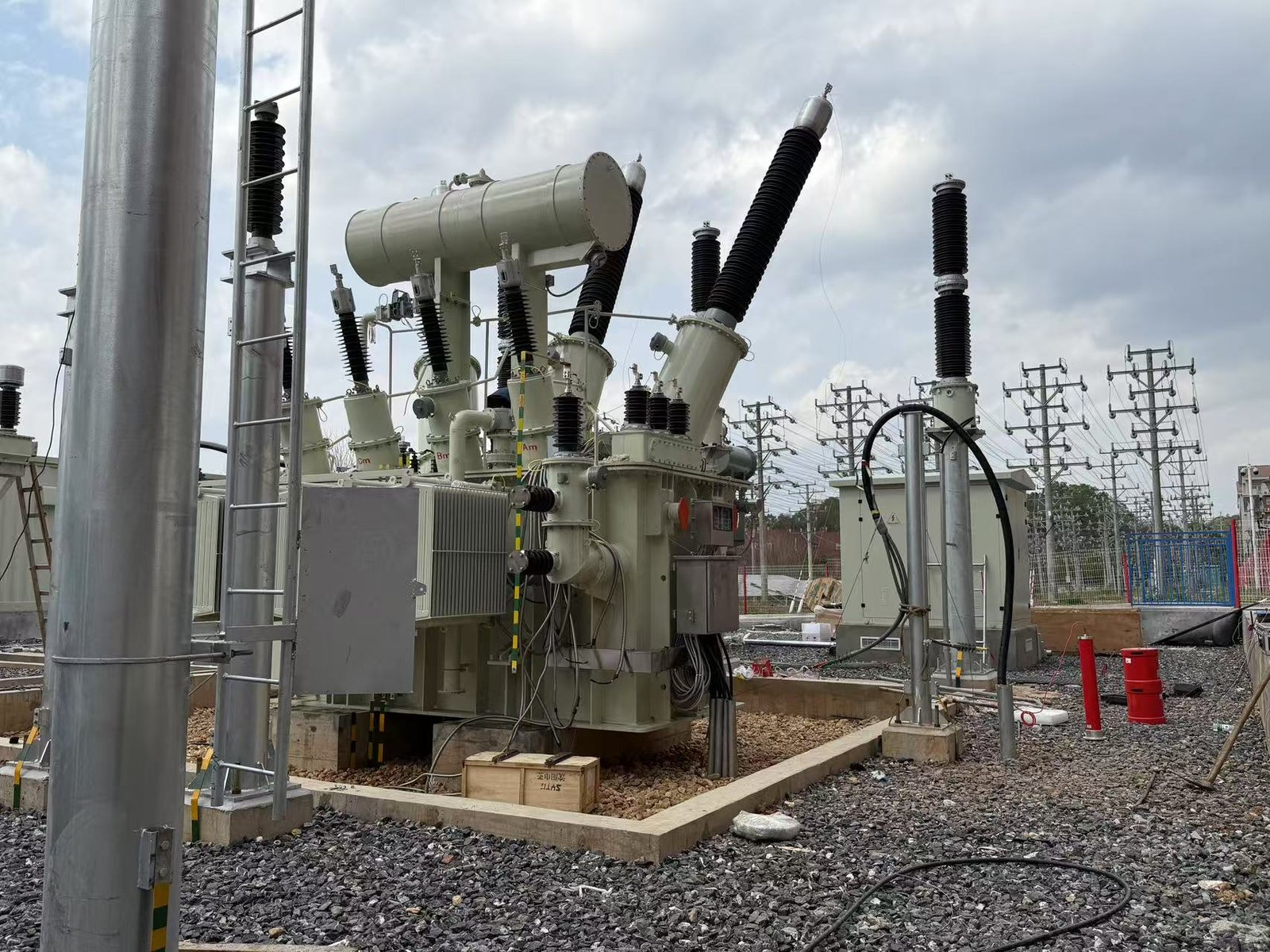
Instantaneous overcurrent in transformers can produce extremely high electrodynamic forces, severe conductor stress, insulation damage, nuisance trips, and even catastrophic failure if it is not cleared quickly. The challenge is that the current may arise from a genuine downstream short circuit, transformer internal fault, energization inrush, or another transient event, so simply setting protection to trip at the lowest possible threshold can create unwanted outages. The most effective way to control instantaneous transformer overcurrent is to limit the fault current where practical and coordinate fast-acting protection—such as appropriately set instantaneous/short-time overcurrent elements, fuses, circuit breakers, differential protection, and upstream/downstream protection—with the transformer's rated current, impedance, inrush behavior, and available short-circuit current. The protection should clear genuine faults rapidly while remaining stable during transformer energization and other permissible transients.
Instantaneous overcurrent protection should always trip at the lowest possible current setting.False
An excessively low setting can trip during transformer energization inrush or other legitimate transient conditions. The setting must be coordinated with transformer characteristics, downstream faults, available fault current and applicable protection requirements.
Transformer impedance can limit the magnitude of short-circuit current.True
Transformer leakage impedance contributes directly to the circuit impedance seen during a fault and therefore limits prospective short-circuit current.
What Is Instantaneous Overcurrent?
Instantaneous overcurrent is a condition in which transformer current rises rapidly above a protection threshold and the protective device is designed to operate with little intentional time delay.
Typical causes include:
- Phase-to-phase short circuit
- Phase-to-ground fault
- Three-phase fault
- Internal winding fault
- Bushing fault
- Cable fault
- Busbar fault
- Transformer energization inrush
- Severe external system fault
These events do not all require the same protection response.
The key distinction is:
Fault current must be interrupted quickly; legitimate transient current must not cause an unnecessary trip.
Why Is High Fault Current Dangerous to a Transformer?
A high current produces large electromagnetic forces in transformer windings.
The approximate relationship is:
F \propto I^2
This means that if current increases substantially, the electromagnetic forces can increase even more rapidly.
For example, if current rises from 1 per-unit to 5 per-unit, the corresponding force tendency can scale approximately with:
5^2=25
times the original current-force relationship, assuming comparable geometry and electromagnetic conditions.
These forces can deform:
- Windings
- Conductors
- Clamping structures
- Insulation systems
- Lead connections
A transformer can therefore suffer mechanical damage from a fault even when the fault is cleared relatively quickly.
What Is the First Step in Controlling Instantaneous Overcurrent?
The first step is to determine the prospective fault current at the transformer's location.
A simplified short-circuit model is:
I{sc}\approx\frac{V}{Z{source}+Z{transformer}+Z{system}}
The actual calculation should use the applicable system model and transformer sequence impedances where required.
Important inputs include:
| Parameter | Why It Matters |
|---|---|
| Transformer rating | Establishes base current |
| Primary voltage | Determines operating current |
| Secondary voltage | Determines LV current |
| Transformer impedance | Limits fault current |
| Utility short-circuit level | Determines available source fault current |
| Cable impedance | Adds fault-current limitation |
| Generator contribution | Can change fault current |
| Motor contribution | May contribute during faults |
| Grounding system | Affects earth-fault current |
| Protection settings | Determines clearing behavior |
Without a fault-current study, instantaneous protection settings are essentially educated guesses.
How Does Transformer Impedance Help Limit Fault Current?
Transformer impedance is one of the inherent current-limiting mechanisms.
A higher impedance generally produces a lower prospective short-circuit current, all else being equal.
However, increasing impedance is not automatically beneficial because it can also affect:
- Voltage regulation
- Motor starting
- Fault coordination
- Parallel operation
- System voltage drop
Therefore, transformer impedance should be selected as part of the complete electrical-system design.
How Does a Circuit Breaker Control Instantaneous Overcurrent?
A properly selected circuit breaker detects excessive current and interrupts the fault.
Its short-circuit performance must be compatible with the available fault current.
Buyers should verify:
- Rated voltage
- Continuous current rating
- Interrupting capacity
- Short-time withstand rating
- Peak withstand
- Trip-unit characteristics
- Instantaneous pickup
- Short-time pickup
- Short-time delay
- Ground-fault protection where applicable
The breaker must be able to interrupt the actual prospective fault current, not merely the transformer's normal current.
How Should Instantaneous Pickup Be Set?
There is no universal setting.
A protection engineer normally considers:
- Transformer full-load current.
- Maximum permissible through-fault current.
- Downstream breaker settings.
- Upstream protection.
- Transformer energization inrush.
- Internal fault sensitivity.
- Available short-circuit current.
- Protection coordination.
- CT performance.
- Applicable standards and utility requirements.
The objective is to establish a protection zone in which faults are cleared quickly without compromising selectivity.
Why Must Inrush Current Be Considered?
Transformer energization can create a large transient current even when there is no fault.
The magnitude depends on factors such as:
- Point on voltage waveform at energization
- Residual core flux
- Core magnetic characteristics
- Transformer design
- Source impedance
This is why an instantaneous element that appears perfectly reasonable from a steady-state current perspective can trip during energization.
Protection schemes must distinguish fault current from magnetizing inrush where necessary.
How Does Differential Protection Help?
Transformer differential protection compares current entering and leaving the protected transformer zone.
Under normal operation or external faults, properly compensated currents should approximately balance.
For an internal fault, the differential current becomes significant.
This allows differential protection to provide:
- Fast operation
- High sensitivity
- Selective transformer fault clearing
It is particularly valuable for larger or more critical transformers.
How Does Differential Protection Avoid Tripping During Inrush?
Transformer differential protection can incorporate inrush restraint or blocking techniques.
A traditional method examines harmonic content, particularly the characteristic behavior associated with magnetizing inrush.
Modern numerical relays may use more sophisticated waveform and operating algorithms.
The principle is:
Internal fault → rapid differential operation
Energization inrush → restraint/stability
The exact method depends on the relay design and protection philosophy.
What Role Do Current Transformers Play?
Current transformers, or CTs, provide the protection relay with a scaled representation of primary current.
Poor CT selection can undermine otherwise excellent protection.
Important CT considerations include:
- Ratio
- Accuracy class
- Burden
- Knee-point characteristics where relevant
- Saturation performance
- Wiring resistance
- Fault-current magnitude
During very high faults, CT saturation can distort the measured current.
This can affect differential and overcurrent protection.
How Does CT Saturation Affect Instantaneous Protection?
Suppose the actual primary fault current is extremely high.
If a CT saturates, its secondary current may no longer accurately reproduce the primary waveform.
Consequences can include:
- Reduced relay current
- Distorted waveform
- Delayed operation
- False differential current
- Incorrect protection behavior
Therefore, protection design must consider the maximum fault current and CT transient performance.
How Can Fuses Control Transformer Overcurrent?
Fuses can provide fast fault interruption in appropriate transformer applications.
They are commonly considered for:
- Smaller transformers
- Distribution transformers
- Auxiliary transformers
- Specific MV applications
Advantages can include:
- Fast fault clearing
- Simple construction
- Current-limiting behavior for selected fuse types
- Low maintenance requirements
However, fuses have limitations:
- One-time operation
- Replacement requirements
- Less flexible settings
- Coordination constraints
For large or critical transformers, circuit-breaker-based protection may provide greater flexibility.
How Does Current-Limiting Protection Work?
Some protective devices are designed not merely to interrupt a fault but to limit the peak current and let-through energy.
This can reduce:
- Thermal stress
- Electrodynamic forces
- Arc energy
- Mechanical damage
The benefit depends on the actual device characteristics and fault level.
Buyers should therefore request current-limiting curves or relevant test information rather than relying on a generic “current limiting” description.
How Does Downstream Protection Help?
The best place to interrupt an external fault is often the closest appropriate protective device to the fault.
For example:
Utility
   │
   ▼
MV Protection
   │
   ▼
Transformer
   │
   ▼
LV Main Breaker
   │
   ├── Feeder Breaker A
   ├── Feeder Breaker B
   └── Feeder Breaker C
If Feeder B develops a short circuit, the feeder protection should ideally clear that fault without unnecessarily tripping the transformer primary protection.
This is the basis of selectivity and coordination.
How Does Protection Coordination Reduce Transformer Stress?
Protection coordination establishes appropriate pickup and clearing times between devices.
A simplified coordination hierarchy is:
Load fault → feeder protection → LV main protection → transformer protection → upstream protection
The closer device should normally operate first when its interrupting capability and protection design permit.
Poor coordination can cause:
- Unnecessary transformer trips
- Large-area outages
- Longer fault duration
- Greater thermal and mechanical stress
- Loss of selectivity
What Is the Difference Between Instantaneous and Time-Delayed Protection?
| Feature | Instantaneous | Time-Delayed |
|---|---|---|
| Intentional delay | Minimal/none | Defined delay |
| Main objective | Very high-current faults | Coordination |
| Selectivity | Can be difficult | Often easier |
| Fault clearing | Very fast | Slower |
| Inrush sensitivity | Important | Important |
| Downstream coordination | Requires careful setting | More flexible |
A complete transformer protection scheme commonly uses multiple elements rather than relying on one instantaneous threshold.
How Can Transformer Differential, Overcurrent and Ground-Fault Protection Work Together?
A typical protection philosophy may use:
- Transformer differential protection
- Primary overcurrent
- Ground-fault protection
- Secondary overcurrent
- Overtemperature protection
- Surge protection
- Mechanical protection for oil-filled transformers where applicable
Each function addresses a different failure mechanism.
This layered approach is generally more robust than trying to make one overcurrent relay perform every protection task.
What About Internal Transformer Faults?
Internal faults deserve particularly fast protection.
Possible faults include:
- Winding-to-ground
- Interturn faults
- Phase-to-phase faults
- Lead faults
- Bushing faults
- Core-related faults
For appropriately sized transformers, differential protection can identify many internal electrical faults rapidly.
Oil-filled transformers may additionally use devices such as:
- Buchholz protection where applicable
- Sudden-pressure protection
- Pressure relief devices
- Oil and winding temperature monitoring
Dry-type transformers may instead emphasize:
- Winding temperature monitoring
- Thermal sensors
- Partial-discharge monitoring where specified
- Protection relays
- Cooling supervision
How Does Transformer Temperature Relate to Overcurrent?
Overcurrent produces additional winding heating.
For resistive winding losses, the relationship is approximately:
P_{cu}=I^2R
Thus, doubling current can produce approximately four times the resistive loss for a fixed winding resistance.
This is why repeated overloading can accelerate insulation aging even when individual events do not immediately cause catastrophic failure.
How Can Operators Reduce Repeated Overcurrent?
Control strategies include:
- Load balancing
- Feeder protection
- Proper breaker settings
- Transformer capacity planning
- Automatic load shedding
- Demand management
- Harmonic assessment
- Preventive maintenance
- Condition monitoring
- Thermal monitoring
The goal is not simply to trip the transformer whenever current becomes high.
The goal is to prevent damaging conditions from persisting.
How Does Harmonic Current Affect Transformer Overcurrent?
Nonlinear loads can generate harmonic currents.
Examples include:
- Variable-frequency drives
- UPS systems
- Rectifiers
- Inverters
- Switching power supplies
Harmonic currents can increase additional transformer heating and losses.
Therefore, buyers should consider the expected harmonic spectrum when selecting:
- Transformer rating
- Winding design
- Protection
- Temperature monitoring
- Cooling
How Does Transformer Parallel Operation Affect Overcurrent?
When transformers operate in parallel, fault-current contribution and load sharing become more complex.
Important requirements include compatibility of:
- Voltage ratio
- Polarity
- Phase displacement
- Percentage impedance
- X/R characteristics
- Tap positions
- Power rating
Incorrect parallel operation can produce unequal current sharing and circulating current.
Protection must account for the combined system.
How Does Grounding Affect Instantaneous Overcurrent?
Grounding architecture influences earth-fault current.
An earth fault may produce:
- High fault current
- Moderate fault current
- Relatively low fault current
depending on the system.
Therefore, ground-fault protection cannot be selected from phase-fault assumptions alone.
Buyers should define:
- Neutral grounding method
- Grounding impedance
- Ground-fault current
- Protection sensitivity
- Clearing time
Can Transformer Impedance Alone Solve Overcurrent Problems?
No.
Increasing impedance may reduce short-circuit current, but it cannot replace appropriate protection.
Overcurrent control is a system-level problem.
A robust solution combines:
Fault-current limitation + fast detection + selective interruption + proper transformer design + monitoring.
What Should Buyers Specify in a Transformer RFQ?
Include at least:
| Requirement | Buyer Should Specify |
|---|---|
| Rated power | kVA/MVA |
| Primary voltage | Exact system voltage |
| Secondary voltage | Exact required voltage |
| Frequency | Hz |
| Impedance | Required/acceptable range |
| Short-circuit level | Available fault current |
| Cooling | ONAN/ONAF or dry-type cooling as applicable |
| Protection | Required functions |
| CTs | Ratio and protection requirements |
| Breaker | Rating and interrupting capacity |
| Differential relay | Where applicable |
| Ground fault | Required sensitivity |
| Inrush | Transformer energization characteristics |
| Monitoring | Temperature/condition monitoring |
| Testing | Factory and site tests |
| Coordination | Protection study requirements |
What Tests Help Verify Transformer Overcurrent Protection?
A commissioning program may include:
- CT ratio testing
- CT polarity testing
- CT insulation testing
- Relay secondary-injection testing
- Breaker trip testing
- Breaker timing
- Protection logic verification
- Interlock testing
- Grounding verification
- Transformer ratio testing
- Winding resistance testing
- Insulation testing
- Functional alarm/trip testing
The exact test program should follow the project specifications and applicable standards.
How Should Buyers Evaluate a Supplier's Protection Design?
Ask the supplier to provide:
- Single-line diagram.
- Protection philosophy.
- Relay model.
- CT ratios.
- Protection settings or setting methodology.
- Transformer impedance.
- Short-circuit withstand information.
- Breaker interrupting rating.
- Coordination study interface requirements.
- Factory test documentation.
- Commissioning procedures.
- Protection test records.
A supplier that cannot clearly explain how the transformer is protected against high-current faults deserves additional technical scrutiny.
A Practical Instantaneous-Overcurrent Control Strategy
Use this engineering sequence:
Determine available short-circuit current
                ↓
Determine transformer fault withstand
                ↓
Calculate transformer full-load current
                ↓
Evaluate energization inrush
                ↓
Select CTs
                ↓
Select breaker/fuse
                ↓
Define instantaneous/short-time protection
                ↓
Coordinate downstream protection
                ↓
Coordinate upstream protection
                ↓
Verify differential protection where applicable
                ↓
Test protection and trip circuits
                ↓
Monitor transformer condition during operation
This approach is much more reliable than selecting an instantaneous pickup from the transformer's rated current alone.
Buyer Takeaway
Instantaneous transformer overcurrent is controlled by combining appropriate transformer impedance, correctly rated circuit breakers or fuses, fast overcurrent and differential protection, properly selected CTs, coordinated upstream/downstream settings, suitable grounding protection and consideration of energization inrush. The objective is to clear genuine high-current faults as rapidly as practical while preventing legitimate transient currents from causing unnecessary trips.
For buyers, the most important information is the available short-circuit current, transformer impedance, rated current, inrush behavior, CT performance, breaker interrupting capability and complete protection-coordination study. For critical or high-value transformers, layered protection is generally preferable to relying on a single instantaneous overcurrent element.
The protection design should also be verified through factory documentation, commissioning tests, relay injection tests, breaker tests and site functional testing before energization.
What Causes Instantaneous Overcurrent in Transformers?
Instantaneous overcurrent in a transformer can develop suddenly when current rises far above its normal operating value, creating severe thermal and electromechanical stress and potentially causing protection devices to trip unexpectedly. The difficulty is that not every high-current event is an internal transformer failure: a downstream short circuit, transformer energization inrush, external system fault, incorrect tap configuration, or certain abnormal operating conditions can all produce a rapid current surge. The main causes of instantaneous overcurrent in transformers are internal winding and bushing faults, phase-to-phase or phase-to-ground short circuits, downstream and external system faults, transformer energization inrush, severe overloading, low-impedance fault paths, and abnormal system conditions; distinguishing these causes is essential because a genuine fault requires rapid isolation, whereas normal energization inrush may need restraint or controlled protection.
Every instantaneous overcurrent event means that the transformer has an internal fault.False
External short circuits and transformer energization inrush can also produce high transient current. Protection and monitoring data should be used to distinguish internal faults from external or permissible transient conditions.
Transformer energization can produce a high transient magnetizing current even when there is no short circuit.True
Closing a transformer onto an AC source can produce magnetizing inrush depending on switching angle, residual core flux, core characteristics, and system impedance.
What Is Instantaneous Overcurrent in a Transformer?
Instantaneous overcurrent describes a rapid current increase that exceeds a protective threshold with little or no intentional time delay.
It is useful to distinguish three different concepts:
- Normal load current: expected operating current.
- Overload current: current above the intended continuous loading level.
- Fault current: current caused by an unintended low-impedance electrical path.
A fourth condition is especially important:
- Magnetizing inrush: a potentially very high transient current during transformer energization that is not necessarily a fault.
These conditions can look similar if the only information available is a current measurement.
What Are the Main Causes?
| Cause | Typical Mechanism | Potential Consequence |
|---|---|---|
| Phase-to-phase fault | Low-impedance path between phases | Very high fault current |
| Phase-to-ground fault | Insulation breakdown to ground | High earth-fault current |
| Internal winding fault | Winding insulation failure | Rapid transformer damage |
| Interturn fault | Shorted winding turns | Localized severe heating |
| Bushing fault | Insulation or connection failure | High fault current |
| Downstream short circuit | LV feeder/load fault | Transformer through-fault current |
| External MV fault | Fault elsewhere on supply system | Transformer fault-current contribution |
| Energization inrush | Core saturation after energization | Large transient current |
| Severe overload | Excessive load demand | Thermal stress |
| Incorrect tap configuration | Abnormal voltage/current conditions | Excessive current or overheating |
| Low system impedance | Strong source feeding fault | Higher available fault current |
| Parallel-operation problem | Unequal transformer characteristics | Circulating or unequal currents |
The protection system must distinguish between these conditions.
How Do Internal Transformer Faults Cause Instantaneous Overcurrent?
Internal faults are among the most serious causes.
A transformer contains conductors at substantial electrical potential separated by insulation. If the insulation system fails, a low-impedance current path can develop.
Potential locations include:
- Windings
- Leads
- Bushings
- Connections
- Tap changer components
- Core insulation
- Internal terminals
For example, a winding-to-ground fault can produce substantial current depending on the transformer connection and grounding system.
An internal fault can develop rapidly and should normally be detected and isolated without waiting for ordinary thermal overload protection.
What Is an Interturn Fault?
An interturn fault occurs when insulation between adjacent winding turns breaks down.
This condition can be particularly difficult because the overall transformer current may not immediately appear as an enormous external fault current.
However, the shorted turns can carry very high circulating current locally.
The result may include:
- Intense localized heating
- Rapid insulation deterioration
- Gas generation in oil-filled transformers
- Winding deformation
- Progression to a larger fault
This is one reason transformer differential and specialized condition monitoring can be valuable.
How Do Phase-to-Phase Faults Cause Overcurrent?
A phase-to-phase fault creates a low-impedance connection between conductors at different phases.
The current is then primarily limited by the impedance between the source and fault.
A simplified relationship is:
I{fault}\approx\frac{V}{Z{total}}
where (Z_{total}) includes source, transformer and conductor impedances.
As the effective impedance falls, prospective fault current rises.
This is why transformer impedance and upstream system strength are important procurement parameters.
How Do Phase-to-Ground Faults Cause Overcurrent?
A phase-to-ground fault occurs when an energized conductor contacts ground or a grounded component.
The magnitude depends strongly on:
- Transformer winding connection
- Neutral grounding
- Grounding impedance
- Source impedance
- Fault location
- Fault resistance
A solid ground fault can generate substantial current.
A high-resistance ground fault may produce much less current but can still be dangerous and destructive.
Therefore, phase-fault and ground-fault protection should be evaluated separately.
How Do External Faults Affect the Transformer?
A transformer can experience extremely high through-fault current even when the transformer itself is healthy.
Consider:
Grid
  │
  ▼
Transformer
  │
  ▼
LV Bus
  │
  ├── Feeder A
  ├── Feeder B
  └── Feeder C
          │
          X  ← Short circuit
The feeder fault causes current to flow through the transformer.
The transformer experiences:
- High winding current
- Large electrodynamic forces
- Increased heating
- Mechanical stress
The appropriate downstream protection should clear the fault whenever practical.
Why Can a Healthy Transformer Trip During a Downstream Fault?
Because the transformer is supplying the fault.
The transformer does not know whether the fault is physically inside its tank, in its cable, at a switchboard or several meters downstream unless the protection scheme determines the fault location.
This is why protection coordination is critical.
A transformer primary overcurrent device should not normally be the first device to clear every downstream fault when selective downstream protection is available.
How Does Transformer Energization Cause High Current?
Transformer energization is one of the most important causes of apparent instantaneous overcurrent.
When an AC transformer is energized, the core flux depends on:
- Applied voltage waveform
- Switching instant
- Residual flux
- Core magnetic properties
If the resulting flux drives the core deeply toward saturation, magnetizing current can become very large.
This current is called inrush current.
It may last from several cycles to much longer depending on transformer and system characteristics.
Why Does Switching Angle Matter?
The voltage waveform at the instant of energization determines how the magnetic flux develops.
If the transformer is energized under an unfavorable point-on-wave condition, the flux may be driven significantly away from its steady-state operating trajectory.
Residual magnetism can make the condition more severe.
Consequently:
Switching instant + residual flux + core characteristics → possible magnetizing inrush
This is why instantaneous protection cannot be selected without considering transformer energization behavior.
How Is Inrush Different From a Short Circuit?
| Characteristic | Energization Inrush | Short Circuit |
|---|---|---|
| Cause | Transformer energization | Fault |
| Normal transformer condition | Can be normal | Abnormal |
| Duration | Transient | Persists until cleared |
| Waveform | Often highly distorted | Fault-dependent |
| Differential protection | May require restraint | Should operate for internal faults |
| Harmonic content | Characteristic features may appear | Different waveform characteristics |
| Protection response | Avoid unnecessary trip | Rapid isolation |
The exact waveform is installation-dependent, so relay algorithms should be designed accordingly.
Can Switching a Transformer Back On Cause Inrush?
Yes.
A transformer can retain residual core flux after being disconnected.
If it is re-energized at an unfavorable point on the voltage waveform, the residual flux can combine with the new flux trajectory and increase saturation.
This is particularly relevant to:
- Automatic re-energization
- Transfer schemes
- Automatic reclosing
- Generator switching
- Substation switching
How Does Severe Overloading Cause Overcurrent?
Excessive loading occurs when connected demand exceeds the transformer's intended operating capacity.
Common causes include:
- New loads added without capacity review
- Motor starting
- Production expansion
- Seasonal demand
- HVAC demand
- EV charging
- Data-center load growth
- Poor load balancing
Overload generally develops more slowly than a solid short circuit, but severe overload or a sudden large load connection can still trigger fast protection depending on settings.
How Do Motor Starting Currents Affect Transformer Protection?
Large motors can draw substantially higher current during starting than during steady-state operation.
A transformer feeding several motors may therefore see:
- Starting-current peaks
- Voltage dips
- Repeated current surges
Protection settings must distinguish permissible motor-starting conditions from actual faults.
How Do Inverter and Power-Electronics Loads Contribute?
Modern electrical systems may include:
- Solar inverters
- Battery inverters
- UPS systems
- Variable-frequency drives
- Rectifiers
Their fault-current contribution can differ significantly from conventional synchronous generators.
Therefore, the buyer should not assume that all sources contribute fault current in the same way.
How Does Low Transformer Impedance Increase Fault Current?
Transformer impedance is a major factor in fault-current magnitude.
If transformer impedance is relatively low, a downstream short circuit may result in a higher prospective fault current.
This can be desirable for some voltage-regulation requirements but creates greater short-circuit duty.
If impedance is increased, fault current generally falls, but voltage regulation can worsen.
Thus, transformer impedance is a system-design tradeoff.
How Can Parallel Transformers Cause Abnormal Current?
Transformers operating in parallel should have compatible:
- Voltage ratios
- Polarity
- Phase displacement
- Percentage impedance
- Tap settings
- Power ratings
- Relevant X/R characteristics
If these conditions are poorly matched, circulating current can develop.
Unequal impedance can also cause one transformer to carry disproportionate load.
This can produce unexpected overcurrent and overheating.
How Do Tap Settings Affect Transformer Current?
Tap changers modify the transformer turns ratio.
Incorrect or poorly coordinated tap positions can produce:
- Unexpected secondary voltage
- Unequal parallel load sharing
- Excessive circulating current
- Abnormal loading
On-load tap changers and off-circuit tap changers also have different operating procedures and constraints.
Buyers should therefore define the required tap range and operating philosophy clearly.
How Do Cable Faults Cause Transformer Overcurrent?
A cable connected directly to the transformer can develop:
- Phase-to-phase faults
- Phase-to-ground faults
- Termination failures
- Insulation breakdown
Because the cable may have relatively low impedance, a fault close to the transformer can result in substantial current.
Cable protection should therefore be coordinated with transformer protection.
How Do Loose Connections Produce Overcurrent Problems?
A loose or degraded connection does not necessarily produce a classic short circuit.
Instead, it can create localized resistance.
That resistance causes heating, which can further degrade the connection.
The progression can be:
Loose connection → resistance → heating → insulation damage → arcing → fault current
This is why thermal inspection and connection maintenance are important.
How Does Insulation Failure Lead to Fault Current?
Transformer insulation separates:
- Turns
- Layers
- Phases
- Windings
- Winding-to-core structures
- Winding-to-ground paths
Insulation can deteriorate because of:
- Thermal aging
- Moisture
- Contamination
- Electrical stress
- Mechanical movement
- Partial discharge
- Manufacturing defects
Once insulation breaks down, the resulting fault path can generate a rapid current increase.
How Does Moisture Increase Transformer Risk?
Moisture can reduce insulation dielectric strength and accelerate degradation.
For oil-filled transformers, water may exist:
- Dissolved in insulating oil
- In paper insulation
- At interfaces
For dry-type transformers, humidity can influence insulation surfaces and contamination.
Moisture does not necessarily cause an instantaneous overcurrent event by itself, but it can increase the probability of insulation failure that ultimately produces one.
How Can Partial Discharge Contribute?
Partial discharge is a localized electrical discharge that does not completely bridge the insulation system.
Repeated partial discharge can progressively damage insulation.
A possible degradation path is:
Partial discharge → insulation erosion → dielectric weakness → insulation breakdown → fault current
Monitoring partial discharge can therefore provide an opportunity to identify developing insulation problems before a major fault occurs.
How Do Core Problems Cause Overcurrent?
Core faults generally do not behave exactly like winding short circuits.
Potential problems include:
- Core insulation failure
- Unintended circulating paths
- Localized overheating
- Abnormal flux conditions
Core-related abnormalities can cause heating and insulation deterioration that eventually contributes to larger transformer faults.
Can Overvoltage Cause Instantaneous Overcurrent?
Overvoltage can drive magnetic cores toward saturation under certain operating conditions.
Core saturation can produce increased magnetizing current.
The severity depends on:
- Voltage magnitude
- Frequency
- Transformer design
- Duration
- Residual flux
- System conditions
Therefore, voltage and frequency must be considered together.
What Happens During Low-Frequency Operation?
For a given voltage, reducing frequency increases the volts-per-hertz ratio.
An excessively high V/Hz condition can drive the core toward saturation and increase magnetizing current.
This can occur in unusual operating conditions involving:
- Generator frequency excursions
- Incorrect system operation
- Variable-frequency sources
- Startup conditions
Transformer protection and system controls should account for abnormal V/Hz conditions where relevant.
How Do Harmonics Affect Transformer Current?
Harmonic currents can increase:
- RMS current
- Winding heating
- Stray losses
- Acoustic noise
- Thermal stress
They may not behave like a conventional short circuit, but severe harmonic loading can contribute to overheating and eventual insulation degradation.
For nonlinear loads, buyers should obtain a harmonic assessment before selecting transformer capacity and cooling.
How Does Lightning or Switching Surge Contribute?
Overvoltage transients can stress transformer insulation.
Potential sources include:
- Lightning
- Switching operations
- Fault clearing
- Capacitor switching
- Network disturbances
A transient overvoltage can initiate insulation failure, which may then develop into a high-current fault.
Surge arresters and appropriate insulation coordination are therefore important.
Why Does Transformer Protection Need Multiple Layers?
Different causes require different protection functions.
| Condition | Appropriate Protection Approach |
|---|---|
| Internal phase fault | Differential protection |
| Ground fault | Ground-fault/differential protection |
| External feeder fault | Feeder overcurrent |
| Severe transformer overload | Overload/thermal protection |
| Energization inrush | Differential restraint/blocking or suitable algorithm |
| High temperature | Temperature protection |
| Oil-related internal fault | Gas/pressure protection where applicable |
| Bushing failure | Differential/overcurrent and specialized protection |
| Surge event | Surge protection + insulation coordination |
No single relay element is ideal for every condition.
How Can Operators Determine the Cause After an Overcurrent Trip?
Do not simply reset the breaker.
Investigate:
- Protection relay event record.
- Fault current magnitude.
- Fault duration.
- Phase involved.
- Ground-fault indication.
- Differential current.
- Transformer temperature.
- Breaker operation.
- Downstream feeder status.
- Transformer alarms.
- Oil/gas condition where applicable.
- Insulation condition where indicated.
Modern numerical relays can provide valuable oscillography and event records.
What Does the Event Pattern Tell You?
A useful diagnostic matrix is:
| Observation | Possible Cause |
|---|---|
| Very high current + immediate trip | Short circuit |
| High differential current | Possible internal fault |
| High current only at energization | Inrush |
| One feeder trips | Downstream fault |
| Repeated overload trips | Capacity/load issue |
| High temperature before trip | Thermal overload/cooling problem |
| Ground-fault indication | Ground insulation fault |
| Gas/pressure alarm | Possible internal oil-filled-transformer fault |
| Abnormal relay waveform | CT/protection/system issue |
These observations should be evaluated by qualified personnel rather than interpreted in isolation.
How Can Buyers Reduce the Risk Before Purchasing?
Specify and verify:
- Transformer impedance
- Short-circuit withstand capability
- Protection scheme
- CT performance
- Breaker interrupting capacity
- Differential protection
- Ground-fault protection
- Inrush characteristics
- Temperature monitoring
- Surge protection
- Cooling system
- Harmonic environment
- Factory testing
- Site commissioning
A transformer should be selected for the actual system fault level, not just its kVA/MVA rating.
What Should Be Included in a Technical Transformer Specification?
| Specification Area | Key Requirement |
|---|---|
| Rating | kVA/MVA |
| Primary voltage | Exact voltage |
| Secondary voltage | Exact voltage |
| Frequency | Hz |
| Impedance | Guaranteed value/range |
| Short-circuit duty | System fault level |
| Insulation | Required dielectric levels |
| Cooling | Required cooling method |
| Temperature rise | Guaranteed limit |
| Protection | Required functions |
| CTs | Protection-class requirements |
| Breaker | Interrupting capability |
| Inrush | Energization consideration |
| Grounding | Neutral/earth arrangement |
| Harmonics | Expected load spectrum |
| Surge | Arresters/insulation coordination |
| Monitoring | Temperature and condition monitoring |
| Testing | Factory and site tests |
How Can a Supplier Help Distinguish Causes?
A qualified transformer manufacturer should be able to support the buyer with:
- Short-circuit calculations
- Transformer impedance selection
- Thermal calculations
- Inrush assessment
- Protection interface information
- CT recommendations
- Factory test data
- Installation instructions
- Commissioning support
- Condition-monitoring recommendations
However, final protection settings should be coordinated with the complete electrical-system study and the responsible protection engineer.
Practical Diagnostic Sequence
Instantaneous overcurrent occurs
             ↓
Record relay/event data
             ↓
Determine whether trip occurred during energization
             ↓
Check phase and ground-fault indications
             ↓
Check differential protection
             ↓
Check downstream feeders
             ↓
Calculate/verify available fault current
             ↓
Inspect transformer and connections
             ↓
Check temperature and cooling
             ↓
Test insulation/protection as required
             ↓
Identify root cause
             ↓
Correct fault before re-energization
This is safer than repeatedly closing the breaker and treating the event as a nuisance trip.
Buyer Takeaway
Instantaneous overcurrent in transformers has several possible causes, and the distinction between them is critical. Internal winding, interturn, bushing and phase-to-ground faults can create destructive fault currents. External feeder and system short circuits can also force very high through-fault current through a healthy transformer. Transformer energization can produce substantial magnetizing inrush without any fault, while severe loading, incorrect tap conditions, parallel-operation problems, abnormal V/Hz conditions and power-quality disturbances can create additional overcurrent or thermal stress.
The most important diagnostic question is therefore not simply “Why did the current become high?” but:
“Did the current result from an internal fault, an external fault, a legitimate transient, or an abnormal operating condition?”
Buyers can reduce risk by specifying transformer impedance, short-circuit withstand, protection coordination, CT performance, breaker capability, inrush behavior, grounding, surge protection, cooling and condition monitoring. Operators should use relay event records, differential protection information, feeder status, temperature data and appropriate transformer tests to identify the root cause before re-energization.
How Do Transformer Impedance and Short-Circuit Withstand Capability Control Overcurrent?

Transformer short circuits are among the most severe electrical stresses a power transformer can experience. If prospective fault current is underestimated, the transformer may be exposed to excessive electromagnetic forces, conductor heating, winding deformation, insulation damage, and premature failure. Conversely, specifying unnecessarily high impedance can create excessive voltage drop and poor voltage regulation. Transformer impedance controls the magnitude of prospective short-circuit current by adding electrical reactance to the fault path, while short-circuit withstand capability determines whether the transformer can safely tolerate the resulting thermal and mechanical stresses for the specified fault duration. Buyers should therefore evaluate impedance and withstand capability together: impedance limits fault current, whereas withstand capability ensures the transformer survives the fault until the protection system clears it.
Higher transformer impedance generally reduces prospective short-circuit current.True
For a given source voltage and other system impedances, increasing transformer impedance increases the total impedance of the fault path and therefore reduces prospective fault current.
Transformer short-circuit withstand capability eliminates the need for fast fault protection.False
Withstand capability is a survivability requirement, not a substitute for protection. Protective devices should still detect and clear faults rapidly to limit thermal and mechanical stress.
What Is Transformer Impedance?
Transformer impedance is the effective impedance associated primarily with leakage reactance and winding resistance.
For power-system fault studies, transformer impedance is often expressed as a percentage impedance, or (Z\%).
A transformer marked, for example, with a percentage impedance of 6% means that approximately 6% of rated voltage would produce rated current under the relevant impedance test conditions, subject to the transformer's rated conditions and the impedance definition used by the manufacturer.
The value is fundamental to transformer selection because it influences:
- Short-circuit current
- Voltage regulation
- Fault stress
- Parallel transformer load sharing
- Motor starting voltage drop
- System coordination
Therefore, impedance is not simply a number to copy from an old transformer specification.
How Does Impedance Limit Short-Circuit Current?
The basic relationship is straightforward:
I{sc} \approx \frac{V}{Z{total}}
The total fault-path impedance can include:
- Utility/source impedance
- Transformer impedance
- Cable impedance
- Busbar impedance
- Generator impedance
- Motor contribution
- Other network elements
If transformer impedance increases, total impedance increases, so prospective fault current generally decreases.
For an idealized transformer whose own impedance dominates the fault path, a useful per-unit approximation is:
I{sc,pu}\approx\frac{1}{Z{pu}}
Thus, a transformer with 5% impedance has an approximate transformer-limited symmetrical fault-current contribution of:
\frac{1}{0.05}=20\ pu
while a transformer with 10% impedance would be approximately:
\frac{1}{0.10}=10\ pu
under the simplified assumption that transformer impedance dominates and other system effects are neglected.
These are conceptual calculations rather than complete fault-study results. Actual short-circuit current must account for the complete system impedance and the applicable fault type.
Why Does Percentage Impedance Matter More Than the Transformer Nameplate Alone?
Consider two transformers with the same:
- MVA rating
- Primary voltage
- Secondary voltage
but different impedances.
| Transformer | Rated Power | Example Z% | Simplified Transformer-Limited Fault Current |
|---|---|---|---|
| A | 10 MVA | 5% | 20 pu |
| B | 10 MVA | 6% | 16.67 pu |
| C | 10 MVA | 8% | 12.5 pu |
| D | 10 MVA | 10% | 10 pu |
| E | 10 MVA | 12% | 8.33 pu |
This illustrates an important procurement principle:
A transformer with the same MVA rating can impose a very different short-circuit duty on the connected LV or MV system depending on its impedance.
How Can Buyers Estimate Transformer-Limited Fault Current?
For a simplified three-phase system, the transformer-rated current can be estimated from:
I_{rated}=\frac{S}{\sqrt{3}V}
where:
- (S) = transformer apparent power
- (V) = line-to-line voltage
If transformer impedance is the dominant limitation, the approximate symmetrical short-circuit current is:
I{sc}\approx I{rated}\frac{100}{Z\%}
For example, suppose a 10 MVA, 11 kV/0.4 kV transformer has 6% impedance.
Its 400 V rated secondary current is approximately:
I_{rated}=\frac{10,000,000}{\sqrt3(400)}
\approx14.4\text{ kA}
The simplified transformer-limited fault current would then be approximately:
14.4\times\frac{100}{6}
\approx240\text{ kA}
However, this should not be interpreted as the actual fault current at the LV terminals without considering source impedance, cables, busbars, fault type and other network contributions. In practice, the system fault level can be substantially lower.
Why Is Higher Impedance Not Always Better?
It might seem that buyers should simply specify the highest possible impedance to reduce fault current.
That approach is incorrect.
Higher transformer impedance can increase:
- Voltage drop
- Voltage regulation
- Motor-starting voltage drop
- Sensitivity to load changes
It can also affect parallel operation.
Therefore, transformer impedance represents a compromise:
Lower impedance → better voltage regulation but higher fault current
Higher impedance → lower fault current but potentially poorer voltage regulation
The correct value depends on the complete electrical system.
How Does Impedance Affect Voltage Regulation?
Transformer impedance causes voltage drop when current flows through the transformer.
Under load, the secondary terminal voltage differs from the no-load voltage.
Higher impedance generally produces greater voltage variation between no-load and load conditions.
This can be important for facilities with:
- Large motors
- Long LV feeders
- Sensitive electronic loads
- Welding equipment
- Industrial furnaces
- Data centers
- Large rectifiers
Therefore, buyers should not optimize short-circuit current without checking the normal operating voltage requirements.
How Does Impedance Affect Motor Starting?
Large motors can require several times their normal operating current during starting.
A transformer with relatively high impedance can experience greater voltage drop during motor starting.
This may cause:
- Slow acceleration
- Contactor dropout
- Control-system problems
- Lighting flicker
- Process interruptions
- Drive or inverter faults
Consequently, buyers should evaluate transformer impedance together with motor-starting requirements.
What Is Short-Circuit Withstand Capability?
Short-circuit withstand capability describes the transformer's ability to withstand the thermal and mechanical effects of a specified short circuit for a specified duration without unacceptable damage.
This is fundamentally different from impedance.
Impedance asks:
How much fault current will flow?
Withstand capability asks:
Can the transformer survive that fault current until protection clears it?
Both questions are essential.
Why Are Mechanical Forces So Important?
Transformer winding forces are strongly related to current magnitude.
A simplified relationship is:
F\propto I^2
Therefore, fault-current magnitude has a major effect on electromechanical stress.
If current increases from 1 unit to 5 units, the corresponding force tendency can increase by approximately:
5^2=25
times, assuming comparable geometry.
This explains why a short circuit that lasts only a short period can still deform windings.
Potential damage includes:
- Radial winding deformation
- Axial displacement
- Conductor buckling
- Spacer movement
- Clamping-system stress
- Lead displacement
- Insulation compression
How Does Fault Duration Affect Thermal Stress?
Electrical heating follows the approximate relationship:
E_{thermal}\propto I^2t
where (I) is current and (t) is duration.
This means both current magnitude and clearing time matter.
For example, reducing fault-clearing time can significantly reduce the thermal energy deposited in the transformer.
This creates a direct relationship between:
Transformer withstand capability ↔ Protection clearing time
The transformer must be capable of surviving the specified fault until protection operates.
How Are Thermal and Mechanical Withstand Different?
| Stress Type | Main Driver | Potential Damage |
|---|---|---|
| Thermal | (I^2t) | Conductor overheating |
| Mechanical | Approximately (I^2) force relationship | Winding deformation |
| Dielectric | Voltage/current transient conditions | Insulation failure |
| Structural | Electromagnetic forces + clamping | Movement/displacement |
A transformer can have sufficient thermal withstand but still require careful mechanical design against electrodynamic forces.
What Is the Relationship Between Transformer Impedance and Withstand?
The two parameters should be evaluated as a pair.
For example:
System Fault Level
       ↓
Source Impedance
       ↓
Transformer Impedance
       ↓
Prospective Fault Current
       ↓
Electromagnetic + Thermal Stress
       ↓
Transformer Short-Circuit Withstand
       ↓
Protection Clearing Time
       ↓
Transformer Survival
A transformer should not be specified simply as “6% impedance” without considering the available system fault current and required withstand duration.
How Does the Utility Short-Circuit Level Affect Transformer Stress?
Transformer impedance does not operate in isolation.
Suppose the utility network is very strong and has a high short-circuit capacity.
The transformer can then be exposed to greater prospective fault current than it would see on a weak network.
Important utility information includes:
- Maximum fault current
- Minimum fault current
- Short-circuit MVA
- X/R ratio
- Ground-fault characteristics
- Available fault contribution
The buyer should request this information early in the project.
Why Does the X/R Ratio Matter?
The fault-current waveform contains both AC and DC components.
The X/R ratio influences the decay of the DC offset and therefore the asymmetrical peak current.
This matters for:
- Circuit-breaker making duty
- Busbar mechanical stress
- CT performance
- Transformer mechanical withstand
- Protection calculations
Therefore, symmetrical RMS fault current alone may not be sufficient for complete equipment-duty assessment.
What Is the Difference Between Symmetrical and Asymmetrical Fault Current?
Symmetrical fault current is the balanced AC component.
Actual fault current immediately after fault inception can contain a decaying DC component, producing an asymmetric waveform.
Consequently:
Asymmetrical peak current can be significantly higher than the symmetrical RMS current.
This is important when evaluating:
- Breaker peak making current
- Busbar withstand
- Transformer winding mechanical stress
- CT saturation
How Does Protection Clearing Time Protect the Transformer?
Protection should detect and isolate faults as quickly as practical.
Typical layers can include:
- Differential protection
- Instantaneous overcurrent
- Short-time overcurrent
- Ground-fault protection
- Feeder protection
- Upstream backup protection
For an internal transformer fault, transformer differential protection may provide particularly fast isolation for appropriately designed systems.
For a downstream fault, feeder protection should ideally clear the fault first when coordination permits.
Why Is Protection Coordination Important?
Suppose a feeder fault occurs downstream of a transformer.
If the feeder breaker clears the fault quickly, transformer stress is limited.
If the feeder protection fails and the transformer primary protection eventually clears the fault, the transformer may experience a longer-duration through-fault.
Therefore, the transformer's short-circuit withstand design should consider the backup protection clearing time, not only the fastest expected protection operation.
How Does the Transformer Connection Affect Fault Current?
The transformer winding connection influences fault behavior.
Important characteristics include:
- Delta/wye connection
- Neutral availability
- Grounding method
- Zero-sequence impedance
- Phase displacement
A phase-to-phase fault and a phase-to-ground fault do not necessarily produce the same current.
Therefore, buyers should not use a single generic short-circuit current for every protection calculation.
How Does Grounding Affect Withstand Requirements?
Grounding affects earth-fault current.
For example, systems may use:
- Solid grounding
- Resistance grounding
- Reactance grounding
- Other engineered grounding arrangements
The grounding method influences:
- Ground-fault current
- Protection sensitivity
- Transformer neutral stress
- System voltage during faults
This must be considered in the transformer and protection specification.
How Does Parallel Transformer Operation Change the Situation?
When transformers operate in parallel, each transformer may contribute to the fault.
The total fault current can therefore be greater than the contribution from a single transformer.
Parallel operation also requires appropriate compatibility of:
- Voltage ratio
- Polarity
- Phase displacement
- Percentage impedance
- Tap position
- Power rating
- Relevant X/R characteristics
A mismatch can produce circulating current or unequal load sharing.
What Should Buyers Ask Suppliers About Short-Circuit Withstand?
A transformer RFQ should clearly identify:
| Requirement | Buyer Question |
|---|---|
| Fault level | What is the maximum prospective fault current? |
| Duration | What protection clearing duration is assumed? |
| Thermal withstand | What short-circuit thermal withstand is demonstrated? |
| Mechanical withstand | What electrodynamic withstand is demonstrated? |
| Standard | Which applicable standard/test method is used? |
| Impedance | What is the guaranteed impedance? |
| Tolerance | What impedance tolerance applies? |
| Ground faults | What fault types are included? |
| Parallel operation | Will multiple transformers contribute? |
| Test evidence | What short-circuit test or design evidence is available? |
Do not accept an unspecified statement such as “short-circuit proof.”
The requirement should be technically defined.
What Standards Should Be Considered?
The exact requirements depend on jurisdiction, transformer type and application, but buyers commonly encounter standards from organizations such as:
- IEC
- IEEE
- ANSI
- NEMA
- Local electrical authorities
For example, transformer short-circuit withstand requirements are addressed within the applicable transformer standards, while installation and protection requirements may be governed by separate electrical codes and utility specifications.
The buyer should specify the governing standard explicitly in the RFQ rather than allowing each supplier to quote against a different technical basis.
How Can Buyers Compare Two Transformer Quotations?
Suppose two suppliers offer the same nominal rating.
| Parameter | Supplier A | Supplier B | Procurement Question |
|---|---|---|---|
| Rated power | 10 MVA | 10 MVA | Same? |
| HV | 11 kV | 11 kV | Same? |
| LV | 0.4 kV | 0.4 kV | Same? |
| Impedance | 5% | 8% | Which system requirement governs? |
| No-load loss | Lower | Higher | Lifecycle impact? |
| Load loss | Higher | Lower | Loading profile? |
| Cooling | Standard | Enhanced | Ambient/load conditions? |
| Short-circuit withstand | Specified | Unclear | Reject ambiguity |
| Protection interface | Complete | Basic | Scope difference? |
| Factory tests | Comprehensive | Limited | Quality evidence? |
The lower purchase price does not automatically represent the better transformer.
How Does Impedance Affect Downstream Equipment Ratings?
Transformer impedance influences prospective fault current at the secondary bus.
That affects the required ratings of:
- LV circuit breakers
- Switchboards
- Busbars
- Disconnects
- Fuses
- Cables
- Motor-control equipment
A transformer with lower impedance can increase the fault-current duty of downstream equipment.
Therefore, changing transformer impedance late in a project can force changes elsewhere.
Why Should Buyers Avoid Changing Impedance Without Rechecking the System?
Imagine a project originally designed around an 8% impedance transformer.
If procurement replaces it with a 5% impedance transformer without updating the short-circuit study, the prospective fault current may increase.
Potential consequences include:
- Insufficient breaker interrupting capacity
- Inadequate busbar withstand
- Protection coordination changes
- Higher transformer mechanical stress
- Higher arc-flash energy in applicable systems
This is why transformer substitutions should undergo engineering review.
How Does Short-Circuit Capability Affect Transformer Design?
Manufacturers address fault withstand through mechanical and electrical construction, including:
- Winding geometry
- Conductor selection
- Radial support
- Axial clamping
- Spacers
- Insulation structure
- Clamping pressure
- Lead support
- Core and winding assembly
- Tank and structural design
The exact design depends on transformer construction and rated fault duty.
A credible supplier should be able to explain how the specified fault duty has been considered.
How Can Buyers Verify the Manufacturer's Claims?
Request:
- Routine test reports.
- Design calculations where appropriate.
- Short-circuit withstand documentation.
- Type-test evidence where applicable.
- Guaranteed impedance.
- Impedance tolerance.
- Factory inspection records.
- Winding resistance results.
- Transformer ratio results.
- Leakage impedance results where specified.
- Protection interface documentation.
For high-value transformers, independent inspection or witness testing may also be appropriate.
Can Condition Monitoring Reduce Short-Circuit Risk?
Condition monitoring cannot prevent every external short circuit, but it can identify deterioration that increases the probability of an internal fault.
Useful monitoring may include:
- Winding temperature
- Oil temperature
- Dissolved gas analysis for oil-filled transformers
- Moisture
- Partial discharge
- Bushing condition
- Load current
- Voltage
- OLTC condition
- Cooling-system status
The purpose is to identify developing problems before insulation failure or mechanical damage results in a major fault.
What Is the Most Reliable Procurement Approach?
A practical sequence is:
Determine normal load
        ↓
Determine transformer rating
        ↓
Obtain utility fault level
        ↓
Calculate system short-circuit current
        ↓
Select appropriate transformer impedance
        ↓
Check downstream equipment fault ratings
        ↓
Define thermal and mechanical withstand
        ↓
Define protection clearing times
        ↓
Coordinate protection
        ↓
Specify applicable standards
        ↓
Verify supplier test/design evidence
        ↓
Approve final transformer design
This approach prevents the common mistake of treating transformer impedance and short-circuit withstand as independent specifications.
Buyer Takeaway
Transformer impedance and short-circuit withstand capability solve two different but closely connected problems. Impedance limits the prospective fault current by increasing the impedance of the fault path. Short-circuit withstand capability determines whether the transformer can tolerate the thermal and electrodynamic forces generated by that fault until the protection system clears it.
For procurement, buyers should therefore evaluate transformer percentage impedance, utility short-circuit level, system X/R ratio, fault type, asymmetrical current, protection clearing time, downstream equipment ratings and transformer short-circuit withstand evidence as one coordinated engineering package.
Do not automatically choose the highest transformer impedance. Excessive impedance can create voltage-regulation and motor-starting problems. Instead, select an impedance that satisfies the complete power-system design while ensuring adequate transformer and downstream equipment withstand.
Likewise, do not treat a short-circuit withstand rating as permission for faults to remain uncleared. The transformer should be strong enough to survive the specified fault duty, while protection should clear the fault as quickly and selectively as practical.
How Do Circuit Breakers, Relays, and Differential Protection Control Transformer Overcurrent?
Transformer overcurrent is dangerous because a fault can generate forces and heating far beyond normal operating conditions, yet not every current surge represents a transformer fault. A downstream short circuit, energization inrush, external grid fault, or genuine internal winding fault can all produce abnormal current. If protection is poorly coordinated, the transformer may trip unnecessarily, remain exposed to damaging fault energy, or fail to isolate an internal fault quickly enough. Circuit breakers interrupt the fault current, protective relays detect abnormal electrical conditions and command the breaker to operate, while transformer differential protection compares currents entering and leaving the protected transformer zone to identify internal faults rapidly. Used together with correctly selected CTs, coordinated pickup settings, appropriate interrupting capacity, and inrush restraint, these devices form a layered protection system that limits transformer thermal and mechanical stress while maintaining selectivity.
A protective relay itself normally interrupts the transformer fault current.False
A protection relay primarily detects abnormal conditions and issues a trip command. The circuit breaker or other interrupting device performs the actual current interruption.
Transformer differential protection can distinguish many internal transformer faults from external through-faults when properly designed and applied.True
Differential protection compares appropriately compensated currents on both sides of the transformer. Internal faults produce differential current, while healthy through-faults should substantially balance within the protection zone.
How Do the Three Protection Functions Work Together?
The simplest way to understand the protection chain is:
Abnormal current
      ↓
Current transformer (CT)
      ↓
Protective relay
      ↓
Trip command
      ↓
Circuit breaker
      ↓
Fault current interrupted
Differential protection adds another layer:
HV CT ──► Transformer ──► LV CT
  │                         │
  └──── Differential Relay ─┘
               ↓
        Internal-fault decision
               ↓
         Breaker trip
The devices have different responsibilities:
| Device/Function | Primary Job | Typical Response |
|---|---|---|
| Current transformer | Scale high current for measurement | Continuous measurement |
| Overcurrent relay | Detect excessive current | Fast or time-coordinated trip |
| Differential relay | Detect current imbalance inside zone | Very fast internal-fault trip |
| Circuit breaker | Interrupt fault current | Physically opens circuit |
| Ground-fault protection | Detect earth-fault conditions | Fast/selective trip |
| Thermal protection | Detect excessive temperature/loading | Time-dependent protection |
The important point is that protection is a system, not a single component.
What Does a Circuit Breaker Do?
A circuit breaker is the device that physically interrupts current.
For transformer protection, its key characteristics include:
- Rated voltage
- Continuous current rating
- Interrupting capacity
- Short-time withstand
- Peak making current
- Operating time
- Trip-unit characteristics
- Insulation level
- Mechanical endurance
- Control power requirements
The breaker must be capable of interrupting the actual prospective fault current at its installation point.
A breaker with insufficient interrupting capability is not made safe simply because the transformer has a lower MVA rating.
What Does a Protective Relay Do?
A protective relay measures electrical quantities and determines whether an abnormal condition exists.
Depending on the relay, it may monitor:
- Current
- Voltage
- Frequency
- Differential current
- Ground current
- Negative-sequence current
- Temperature inputs
- Other transformer condition signals
When the relay determines that a trip condition exists, it sends a signal to the circuit breaker's trip circuit.
Modern numerical relays can also record:
- Fault waveform
- Event sequence
- Trip timing
- Pickup information
- Alarm states
- Communication data
This information is extremely useful when investigating an overcurrent event.
What Is Overcurrent Protection?
Overcurrent protection operates when current exceeds a specified threshold.
The main functions may include:
- Instantaneous overcurrent
- Short-time overcurrent
- Time-overcurrent
- Ground overcurrent
The settings must be coordinated with transformer rated current and the wider electrical network.
A simplified relationship is:
I=\frac{V}{Z}
A lower fault-path impedance produces a higher prospective current.
Why Is Instantaneous Protection Useful?
Instantaneous protection is designed to respond to very high currents with minimal intentional delay.
It is valuable for severe faults because reducing clearing time reduces:
- Thermal energy
- Winding mechanical stress
- Arc energy
- Conductor damage
- Insulation stress
However, an instantaneous element cannot simply be set extremely low.
It must remain stable during legitimate transient conditions.
Why Can an Instantaneous Relay Trip During Transformer Energization?
When a transformer is energized, magnetizing inrush can produce a very large transient current.
The current can be affected by:
- Switching point on the voltage waveform
- Residual core flux
- Core design
- Source impedance
- Transformer construction
If the instantaneous pickup is set without considering inrush, the relay may interpret normal energization as a fault.
This is why transformer protection requires careful coordination between inrush behavior and relay settings.
What Is Differential Protection?
Transformer differential protection, commonly associated with ANSI device function 87T, compares currents on different sides of the transformer.
Under normal load:
HV current
    ↓
[ Transformer ]
    ↑
LV-equivalent current
After ratio, phase-shift and connection compensation, the currents should substantially balance.
For an internal fault:
HV current  ──► [ FAULT ] ◄── LV contribution
                       ↓
               Differential current
                       ↓
                  Relay trip
The resulting differential current can be used to identify a fault inside the protected zone.
Why Is Differential Protection Faster for Internal Faults?
Overcurrent protection often has to coordinate with other protection devices.
Differential protection, by contrast, can define a specific transformer zone.
If the fault is inside that zone, the relay can operate without waiting for downstream protection to clear the fault.
This makes differential protection particularly valuable for:
- Large power transformers
- Critical industrial transformers
- Grid transformers
- Generator step-up transformers
- Important substation transformers
The exact protection philosophy depends on transformer size, system design and applicable standards.
How Does Differential Protection Avoid Tripping for External Faults?
Consider a short circuit downstream of the transformer:
Grid
 │
HV CT
 │
Transformer
 │
LV CT
 │
LV feeder ───── X
               Fault
The transformer supplies the external fault, so very large current can pass through it.
But if the HV and LV currents are properly measured and compensated, the current entering and leaving the transformer protection zone should correspond.
The differential relay should therefore remain stable for a healthy transformer experiencing an external through-fault.
This is one of the fundamental advantages of differential protection.
What Is Transformer Differential Restraint?
Modern transformer differential relays generally incorporate a restraint or bias characteristic.
The relay evaluates both:
- Differential current
- Restraining/through current
The purpose is to prevent incorrect operation during conditions such as:
- External short circuits
- CT saturation
- Transformer energization
- Measurement mismatch
The exact algorithm varies by relay manufacturer.
Why Are CTs Critical to Differential Protection?
Differential protection is only as reliable as its current measurements.
CTs on different transformer sides must be selected and connected so that the relay can correctly compare the currents.
Important parameters include:
- CT ratio
- Accuracy
- Burden
- Saturation behavior
- Protection class
- Knee-point performance where applicable
- Secondary wiring resistance
- Maximum fault current
Incorrect CT design can cause either:
- Failure to trip for an internal fault, or
- False tripping during an external fault
Both are serious protection problems.
What Is CT Saturation?
During a severe fault, the magnetic core of a CT can become saturated.
When this occurs, the secondary current may no longer faithfully reproduce the primary current.
For differential protection, unequal CT saturation can create an apparent current imbalance.
Without appropriate relay stabilization, this could produce an unwanted differential trip.
This is why CT selection and relay characteristics must be designed together.
How Does Differential Protection Deal With Transformer Ratio?
The currents on the HV and LV sides are not normally equal in magnitude.
For example, a transformer that steps voltage down substantially will have a correspondingly higher LV current.
The relay therefore needs to compare appropriately normalized currents rather than simply comparing raw amperes.
Modern numerical relays can perform:
- Ratio compensation
- Phase compensation
- Vector-group compensation
- Zero-sequence compensation
- CT mismatch correction
The exact approach depends on the relay.
Why Does the Transformer Vector Group Matter?
Transformer vector group determines the phase relationship between windings.
For example, a delta-wye transformer introduces phase displacement.
If this displacement is not correctly compensated, a differential relay may interpret normal load current as differential current.
Therefore, the relay configuration must match the actual transformer nameplate and winding connection.
How Does Ground-Fault Protection Work?
Ground faults occur when an energized conductor establishes an unintended path to earth or a grounded structure.
Protection can use:
- Residual current
- Neutral current
- Restricted earth fault protection
- Transformer differential protection
- Dedicated ground-fault elements
The appropriate approach depends on the transformer winding connection and grounding system.
What Is Restricted Earth Fault Protection?
Restricted earth fault protection, often called REF, provides sensitive protection for earth faults within a defined winding zone.
It can be particularly valuable because certain winding-to-ground faults may produce current levels that are less obvious to conventional overcurrent protection.
REF therefore complements transformer differential and overcurrent protection.
How Do Circuit Breakers and Relays Coordinate?
The objective is to establish a hierarchy.
A simplified arrangement is:
Transformer
   │
   ├── Differential protection → internal transformer faults
   │
   ├── Overcurrent protection → backup/high-current faults
   │
   └── Temperature/thermal protection → overheating/overload
           │
           ▼
      Circuit breaker
Downstream feeders have their own protection.
If a feeder develops a fault, the feeder breaker should normally operate first where coordination allows.
If the feeder breaker fails, upstream protection provides backup.
What Is Selective Coordination?
Selective coordination means that the protective device closest to the fault should operate before upstream devices whenever technically feasible.
For example:
Transformer
    │
Main breaker
    │
Feeder breaker
    │
Load
    X ← fault
Ideally:
Feeder breaker trips → transformer remains energized.
Poor coordination can cause:
Feeder fault → transformer breaker trips → entire facility loses supply.
This distinction is especially important for critical loads.
How Does Time-Current Coordination Work?
Protection engineers compare the time-current characteristics of protective devices.
The objective is to ensure that:
- Downstream protection operates first
- Transformer protection provides backup
- Breakers remain within their withstand capabilities
- Faults are cleared rapidly enough
- Normal load and starting currents do not cause nuisance trips
The exact settings should be derived from a system protection study rather than copied from generic tables.
How Does Differential Protection Compare With Overcurrent Protection?
| Feature | Overcurrent | Differential |
|---|---|---|
| Basic measurement | Current magnitude | Current balance |
| Main purpose | Excessive current | Internal-zone faults |
| External fault stability | Requires coordination | High when properly applied |
| Internal fault sensitivity | Depends on fault current | Often high |
| Inrush consideration | Important | Critical |
| CT requirements | Important | Especially critical |
| Coordination | Usually required | Zone-based |
| Typical transformer function | Backup/general | Primary internal-fault protection |
For larger transformers, these functions are often complementary rather than competing alternatives.
How Does Circuit-Breaker Interrupting Capacity Affect Protection?
The circuit breaker must be rated for the maximum current it may have to interrupt.
The buyer should evaluate:
- Symmetrical RMS fault current
- Asymmetrical current
- Peak making current
- System X/R ratio
- Voltage
- Breaker operating time
A breaker that can carry transformer full-load current may still be unsuitable for interrupting a high-current short circuit.
Why Does Short-Circuit Withstand Matter?
Transformer protection cannot assume that a breaker operates instantaneously.
There is always some combination of:
- Fault detection time
- Relay processing time
- Trip-circuit time
- Breaker opening time
- Arc interruption time
During this interval, the transformer experiences fault stress.
Short-circuit withstand capability must therefore be compatible with the maximum fault current and protection clearing time.
How Do Overcurrent and Differential Protection Affect Transformer Reliability?
Protection reduces the duration and severity of damaging faults.
For a genuine internal fault:
Fast differential detection → breaker trip → fault isolation → reduced transformer damage.
For an external feeder fault:
Feeder detection → feeder breaker trip → transformer remains in service.
For excessive load:
Thermal/overload protection → controlled response → reduced insulation aging.
This layered philosophy improves both reliability and availability.
How Should Protection Be Applied to Different Transformer Sizes?
The exact scheme depends on the application, but a general approach is:
| Transformer/Application | Typical Protection Emphasis |
|---|---|
| Small distribution transformer | Fuses/overcurrent, temperature as applicable |
| Medium industrial transformer | Breaker + overcurrent + ground fault |
| Large power transformer | Differential + overcurrent + ground fault + thermal/mechanical protection |
| Critical substation transformer | Layered redundant protection |
| Generator step-up transformer | Differential and system-specific generator/transformer protection |
| Oil-filled transformer | Electrical + temperature + gas/pressure-related protection where applicable |
| Dry-type transformer | Electrical + winding temperature + other specified monitoring |
These are general engineering patterns, not universal prescriptions.
What Should Buyers Include in the Transformer RFQ?
Protection requirements should be explicitly stated.
| RFQ Item | What to Specify |
|---|---|
| Transformer rating | kVA/MVA |
| HV/LV voltage | Exact values |
| Transformer impedance | Guaranteed Z% |
| Short-circuit level | Maximum prospective fault current |
| Grounding | Neutral and grounding arrangement |
| Protection relay | Required functions/specification |
| Differential | Required for applicable transformers |
| CTs | Ratio, class and burden requirements |
| Circuit breaker | Voltage/current/interrupting ratings |
| Inrush | Required stability/restraint |
| Coordination | Protection-study requirements |
| Trip circuit | Control voltage and supervision |
| Alarms | Required alarm/trip contacts |
| Testing | Factory and site protection tests |
| Communication | Required protocols/interfaces |
A quotation that simply says “overcurrent protection included” is not technically complete.
How Should Buyers Evaluate a Supplier's Protection Proposal?
Ask the supplier to provide:
- Single-line diagram.
- Protection schematic.
- Relay make/model.
- CT ratios.
- CT protection classes.
- Differential protection philosophy.
- Overcurrent protection functions.
- Ground-fault functions.
- Breaker interrupting rating.
- Protection setting methodology.
- Transformer inrush considerations.
- Short-circuit withstand information.
- Factory test procedures.
- Protection relay test records.
- Commissioning requirements.
This makes it much easier to compare technically different quotations.
What Protection Tests Should Be Performed Before Energization?
A commissioning program may include:
- CT ratio testing
- CT polarity testing
- CT insulation testing
- Relay secondary injection
- Differential protection testing
- Overcurrent pickup testing
- Time-current testing
- Ground-fault testing
- Breaker trip testing
- Breaker timing
- Trip-circuit supervision
- Interlock testing
- Alarm testing
- Transformer ratio testing
- Winding resistance testing
- Insulation tests
The exact test scope should follow the project specification and applicable standards.
How Can Relay Event Records Help Diagnose an Overcurrent Trip?
Modern numerical relays can provide a sequence of events and oscillography.
Useful information includes:
- Which phase operated
- Fault current
- Differential current
- Ground current
- Relay pickup time
- Breaker trip time
- Fault duration
- Protection element that initiated the trip
For example:
| Event Pattern | Possible Interpretation |
|---|---|
| Very high phase current | Short circuit |
| High differential current | Possible internal fault |
| High current without differential operation | Possible external through-fault |
| Current surge during energization | Possible inrush |
| Repeated feeder-related trips | Downstream fault |
| Long-duration high current | Overload/coordination issue |
| Unexpected differential operation | CT/relay/configuration issue |
The event record should be reviewed before attempting re-energization after a serious trip.
What Are Common Protection Design Mistakes?
Setting Overcurrent From Rated Current Alone
Transformer rated current does not tell you the available fault current or required coordination.
Ignoring Inrush
A transformer may trip during energization if instantaneous or differential protection is not properly stabilized.
Using Inadequate CTs
CT saturation and incorrect ratios can compromise differential protection.
Ignoring External Faults
The transformer must withstand through-fault stresses even when the fault is downstream.
Changing Transformer Impedance Without Rechecking Protection
A change in impedance changes prospective fault current and can affect breaker duty and relay settings.
Selecting a Breaker Based Only on Continuous Current
A breaker must also have sufficient short-circuit interrupting capability.
Ignoring Grounding
Ground-fault magnitude and protection sensitivity depend on the system grounding arrangement.
What Is a Practical Transformer Protection Architecture?
A robust architecture can be represented as:
             TRANSFORMER
                  │
       ┌──────────┼──────────┐
       │          │          │
       ▼          ▼          ▼
 Differential  Overcurrent  Thermal
   87T          50/51       49
       │          │          │
       └──────────┼──────────┘
                  │
          Ground Fault / REF
                  │
                  ▼
           Trip Logic
                  │
                  ▼
          Circuit Breaker
                  │
                  ▼
          Fault Isolation
For oil-filled transformers, additional functions may include:
- Gas detection
- Sudden-pressure protection
- Pressure relief
- Oil temperature
- Winding temperature
For dry-type transformers, emphasis may include:
- Winding temperature
- Thermal sensors
- Cooling supervision
- Partial-discharge monitoring where specified
What Is the Best Way to Control Transformer Overcurrent?
The most effective strategy is not to rely on a single protection device.
Instead:
1. Determine the system fault level.
2. Select transformer impedance appropriately.
3. Verify transformer short-circuit withstand.
4. Select CTs for the actual fault duty.
5. Apply differential protection where appropriate.
6. Apply overcurrent and ground-fault backup protection.
7. Select a breaker with adequate interrupting capacity.
8. Coordinate protection with downstream equipment.
9. Account for transformer energization inrush.
10. Test the complete protection chain before energization.
This creates a protection system that is both fast and selective.
Buyer Takeaway
Circuit breakers, protective relays and differential protection control transformer overcurrent through different but complementary functions. The relay detects abnormal current or current imbalance; differential protection identifies faults within the transformer protection zone; and the circuit breaker physically interrupts the fault current. Overcurrent and ground-fault elements provide additional protection and backup, while CTs provide the measurement foundation for the entire scheme.
For buyers, the critical specifications are not merely “breaker included” or “relay included.” The quotation should define transformer impedance, prospective short-circuit current, short-circuit withstand capability, CT ratios and accuracy, differential protection, overcurrent settings, ground-fault protection, breaker interrupting capacity, inrush stability, protection coordination and testing.
The strongest design is one that combines fast internal-fault protection with selective downstream protection. This prevents unnecessary transformer outages while minimizing the duration of faults that can cause winding deformation, thermal damage and insulation deterioration.
How Can Buyers Distinguish Transformer Inrush Current From Dangerous Overcurrent?
A transformer can draw a very large current during energization even when it is completely healthy, while a genuine internal or external fault can produce similarly alarming current levels. Treating every high-current event as a transformer failure can cause unnecessary outages, whereas treating a dangerous fault as harmless inrush can result in catastrophic winding, insulation, or fire damage. Buyers should distinguish transformer inrush current from dangerous overcurrent by evaluating when the current occurred, its waveform and duration, phase relationships, differential-current behavior, harmonic content, voltage conditions, relay operation, and whether the event coincided with energization or an established system fault. Inrush is normally associated with transformer energization and should decay, while dangerous fault current generally persists until the fault is cleared and may produce significant differential or ground-fault indications.
A transformer can experience high inrush current during normal energization without having an internal electrical fault.True
Core flux can temporarily drive the magnetic core toward saturation after energization, producing a large transient magnetizing current in a healthy transformer.
Current magnitude alone is sufficient to determine whether a transformer event is inrush or a dangerous fault.False
Both inrush and faults can produce high current. Timing, waveform, differential protection, harmonic characteristics, voltage behavior, relay records and system conditions should be evaluated together.
Why Is Distinguishing Inrush From Fault Current So Important?
The distinction affects both transformer reliability and protection coordination.
If a healthy transformer is energized and the protection system incorrectly interprets inrush as an internal fault, the result may be:
- Unnecessary breaker operation
- Transformer outage
- Production interruption
- Repeated unsuccessful energization
- Accelerated breaker wear
- Loss of system availability
The opposite error is much more serious.
If an internal fault is mistaken for inrush, the transformer can remain connected to the electrical system while experiencing:
- Extremely high winding current
- Electrodynamic forces
- Localized heating
- Insulation damage
- Winding deformation
- Arc damage
- Oil decomposition in oil-filled units
- Escalation into a major transformer failure
Therefore, the correct question is not:
“Is the current high?”
It is:
“What electrical and operating conditions produced the high current?”
What Is Transformer Inrush Current?
Transformer inrush is a transient magnetizing current that can occur when an AC transformer is energized.
It results primarily from the relationship between:
- Applied voltage
- Frequency
- Core magnetic characteristics
- Residual core flux
- Point on the voltage waveform when switching occurs
Under an unfavorable energization condition, the magnetic flux can temporarily move deeply into a nonlinear portion of the core's magnetization characteristic.
The core can approach saturation.
When saturation occurs, the magnetizing inductance falls dramatically, and the transformer can draw a large current from the source.
The important point is:
Large current does not automatically mean large power transfer to a load or an internal short circuit.
It can be predominantly magnetizing current.
What Causes the Inrush to Be Different From Normal Load Current?
Normal load current is associated with energy delivered to the connected load.
Inrush is primarily associated with establishing the transformer's magnetic operating state.
A simplified sequence is:
Breaker closes
     ↓
Transformer energized
     ↓
Core flux develops
     ↓
Residual flux + applied flux
     ↓
Possible core saturation
     ↓
Large magnetizing current
     ↓
Flux settles
     ↓
Current decays toward normal magnetizing/load current
This explains why the timing of the event is one of the strongest diagnostic clues.
What Is Dangerous Transformer Overcurrent?
Dangerous overcurrent can result from:
- Internal phase-to-phase faults
- Winding-to-ground faults
- Interturn faults
- Bushing faults
- Lead faults
- External feeder short circuits
- Bus faults
- Severe overloads
- Abnormal system conditions
Not all dangerous overcurrent is internal.
An external short circuit can produce substantial through-fault current through a healthy transformer.
Therefore, the buyer must distinguish among:
- Energization inrush
- Internal transformer fault
- External system fault
- Overload
- Abnormal operating condition
What Is the First Diagnostic Question?
Ask:
Did the current surge occur immediately when the transformer was energized?
If yes, inrush becomes a major possibility.
If the transformer had already been operating normally and the current suddenly increased, investigate:
- Downstream short circuit
- Internal transformer fault
- Bushing failure
- Cable fault
- Protection malfunction
- Severe load change
This does not prove the cause, but it establishes the correct diagnostic direction.
How Does the Waveform Help Identify Inrush?
Waveform analysis is more informative than simply reading RMS current.
Transformer inrush often has distinctive characteristics such as:
- Strong asymmetry
- DC offset
- Distorted current waveform
- Unequal phase currents
- Decaying envelope
- Significant harmonic components
A numerical protection relay can capture oscillography during the event.
This allows engineers to examine the current rather than relying on a single maximum-current value.
Why Does Harmonic Content Matter?
Magnetizing inrush is associated with core saturation and therefore can contain substantial low-order harmonic content, traditionally making second-harmonic restraint an important transformer differential-protection technique.
However, modern transformer protection should not be reduced to the simple rule:
“Second harmonic present = inrush.”
Modern transformer cores, CT behavior, system conditions and relay algorithms can complicate the harmonic signature.
Contemporary differential relays may use combinations of:
- Harmonic restraint
- Harmonic blocking
- Waveform analysis
- Differential-current characteristics
- Negative-sequence information
- Rate-of-change characteristics
- Other manufacturer-specific algorithms
The actual relay application should therefore follow the protection manufacturer's instructions and the project's protection study.
What Is the Role of Differential Protection?
Transformer differential protection is one of the most useful tools for distinguishing internal faults from many external events.
It compares the appropriately compensated current entering and leaving the transformer protection zone.
Under normal operation:
        HV CT                         LV CT
          │                             │
          ▼                             ▼
      ───► [       TRANSFORMER       ] ───►
             Balanced current
                  ↓
            Small differential
For an internal fault:
        HV CT                         LV CT
          │                             │
          ▼                             ▼
      ───► [    INTERNAL FAULT    ] ◄───
                    ↓
             Differential current
                    ↓
                Trip relay
                    ↓
               Breaker opens
A correctly engineered differential scheme should generally remain stable for external through-faults while responding rapidly to internal faults.
Can Differential Protection Distinguish Inrush?
Yes, when the protection system is appropriately designed.
During energization, the transformer can exhibit high current without the current pattern corresponding to a conventional internal fault.
The differential relay therefore needs appropriate inrush restraint or blocking logic.
This prevents the protection from interpreting normal energization as an internal transformer fault.
The exact operating characteristic depends on the relay technology and application.
What Does an External Fault Look Like?
Consider a short circuit on a downstream feeder:
Utility
  │
  ▼
Transformer
  │
  ▼
LV switchboard
  │
  ▼
Feeder
  │
  X  ← External fault
The transformer may supply very high current into the fault.
However, because the fault is outside the transformer differential zone, appropriately compensated currents should largely balance from the differential relay's perspective.
This distinction is critical:
High through-current does not necessarily mean transformer internal failure.
The transformer must nevertheless be designed to withstand the mechanical and thermal stresses caused by external faults until the appropriate protection clears them.
What Does an Internal Fault Look Like?
For an internal fault:
HV system
    │
    ▼
 [ HV CT ]
    │
    ▼
 ┌───────────────┐
 │  TRANSFORMER  │
 │      X        │ ← Internal fault
 └───────────────┘
    ▲
    │
 [ LV CT ]
The currents entering and leaving the protected zone no longer balance appropriately.
The resulting differential current can cause the differential relay to trip rapidly.
Additional indications may include:
- Ground-fault current
- Gas generation
- Sudden pressure
- Abnormal temperature
- Winding-current imbalance
- Partial discharge history
How Does Fault Duration Help?
Inrush is normally a transient phenomenon.
Its current should generally decrease as the magnetic flux settles.
A fault current, by contrast, normally persists until a protective device interrupts the fault.
This creates a useful diagnostic distinction:
| Characteristic | Likely Inrush | Potential Fault |
|---|---|---|
| Begins at energization | Strong indication | Possible, but less typical |
| Decays after energization | Typical | Not normally |
| Persists during normal operation | Unlikely | More concerning |
| High differential current | Usually restrained | Strong warning for internal fault |
| Ground-fault indication | Not typical | Concerning |
| Downstream feeder trip | Not typical | Possible external fault |
| Gas/pressure alarm | Not typical | Possible internal fault |
| Distorted waveform | Common | Also possible |
| Harmonics | Characteristic | Fault-dependent |
| Repeats every energization | Possible | Requires investigation |
No single row should be used as a definitive diagnosis.
Why Does Residual Flux Matter?
A transformer core can retain magnetic flux after de-energization.
When the transformer is subsequently energized, the existing residual flux combines with the flux produced by the applied voltage.
If the two reinforce each other in an unfavorable way, the core may enter deeper saturation.
This can make the next energization current much larger.
Therefore, two apparently identical transformers can produce different inrush behavior depending on their magnetic history and switching conditions.
Why Does the Switching Point Matter?
The voltage waveform at the moment of energization affects the resulting flux trajectory.
Closing at an unfavorable point on the waveform can produce greater flux excursion.
Therefore:
Switching angle + residual flux + core characteristics → inrush severity
Controlled switching can sometimes reduce transformer energization transients, but its applicability depends on the system and switching equipment.
Can Inrush Damage a Transformer?
Normal transformer inrush is an expected transient phenomenon and should be considered during protection design.
However, repeated or unusually severe energization can impose stress.
Buyers should investigate:
- Repeated breaker trips
- Unusual audible/mechanical effects
- Abnormally long current decay
- Persistent overheating
- Protection misoperation
- Abnormal relay records
If the transformer repeatedly trips when energized, do not simply increase the relay pickup without determining why.
How Should Buyers Use Relay Event Records?
A relay event record can be extremely valuable.
Review:
- Breaker closing time
- Current waveform
- Voltage waveform
- Phase currents
- Ground current
- Differential current
- Harmonic indicators
- Relay element that operated
- Relay pickup time
- Breaker opening time
- Downstream feeder status
A timeline can help:
Breaker closes
     ↓
Current surge
     ↓
Relay measurements
     ↓
Differential / overcurrent / ground elements
     ↓
Relay decision
     ↓
Trip command
     ↓
Breaker opens
The relationship between these events often provides more information than the peak current alone.
What Measurements Should Buyers Require?
A practical transformer monitoring and protection package can include:
| Parameter | Why Monitor It? | Diagnostic Value |
|---|---|---|
| Phase current | Detect loading/fault current | High |
| Neutral/ground current | Detect earth faults | High |
| Differential current | Identify internal-zone faults | Very high |
| Phase voltage | Evaluate system conditions | High |
| Winding temperature | Detect thermal stress | High |
| Top-oil temperature | Assess thermal state | High |
| Dissolved gases | Detect developing oil/insulation faults | High for oil-filled units |
| Moisture | Assess insulation condition | High |
| Partial discharge | Identify insulation deterioration | High where applicable |
| Breaker status | Establish event sequence | High |
| Relay oscillography | Analyze transient waveform | Very high |
| Tap position | Correlate operating state | Medium/high |
| Cooling status | Explain thermal abnormalities | High |
This combination allows the engineer to correlate electrical events with transformer condition.
How Does Temperature Help?
Temperature cannot normally distinguish inrush by itself.
But it can help establish whether a current event caused sustained thermal stress.
For example:
Short energization inrush + no abnormal temperature rise is generally less concerning than:
Persistent high current + rapidly increasing winding temperature.
For oil-filled transformers, monitoring may include:
- Top-oil temperature
- Winding hot-spot temperature
- Ambient temperature
For dry-type transformers, winding temperature sensors and thermal protection are particularly important.
How Does Dissolved Gas Analysis Help?
For oil-filled transformers, dissolved gas analysis (DGA) can provide evidence of developing internal problems.
Certain abnormal gas patterns can be associated with:
- Thermal faults
- Electrical discharges
- Arcing
- Insulation degradation
DGA is not normally a real-time method for deciding whether a current spike occurring this second is inrush.
Instead, it provides condition context.
If a transformer has repeated unexplained trips and DGA shows an abnormal trend, the case for deeper internal investigation becomes stronger.
How Does Partial Discharge Monitoring Help?
Partial discharge can indicate localized insulation deterioration.
If a transformer has:
- Repeated unexplained trips
- Abnormal differential behavior
- Partial-discharge activity
- Deteriorating insulation indicators
then assuming every event is simple inrush would be unsafe.
Condition monitoring should therefore supplement—not replace—electrical protection.
How Do Buyers Distinguish the Events in Practice?
A practical decision matrix is useful:
| Observation | Initial Interpretation | Recommended Investigation |
|---|---|---|
| Current surge exactly at energization and decays | Inrush likely | Verify relay inrush stability |
| Current surge during normal operation | Fault/overload concern | Analyze relay records and system state |
| High current + high differential | Internal fault concern | Do not re-energize without engineering assessment |
| High current + feeder trip | External fault likely | Investigate feeder/system fault |
| Ground current + differential | Internal ground fault possible | Immediate fault investigation |
| High current + high temperature | Overload/thermal concern | Check loading and cooling |
| Repeated energization trips | Inrush or protection issue | Review switching and relay settings |
| Abnormal DGA trend | Internal condition concern | Condition assessment |
| Partial discharge increasing | Insulation concern | Insulation diagnostic program |
The matrix is a starting point, not a substitute for a protection engineer's investigation.
What Should Buyers Specify for Transformer Protection?
The RFQ should explicitly address transformer energization.
Important requirements include:
- Transformer rated current
- Transformer impedance
- Maximum system fault level
- Short-circuit withstand
- Differential protection
- Overcurrent protection
- Ground-fault protection
- CT ratios
- CT accuracy
- CT saturation performance
- Inrush characteristics
- Relay inrush restraint
- Breaker operating time
- Protection coordination
- Event recording
- Oscillography
- Commissioning tests
A vague requirement such as “provide transformer overcurrent protection” leaves too much room for different technical interpretations.
How Should Buyers Evaluate Relay Settings?
Relay settings must balance two competing objectives:
Trip quickly for dangerous faults.
Remain stable during legitimate transient conditions.
Settings should therefore consider:
- Transformer full-load current
- Emergency loading requirements
- Energization inrush
- Motor-starting current
- Downstream fault current
- CT characteristics
- Transformer impedance
- Grounding method
- Protection coordination
- Breaker characteristics
Do not copy settings from another transformer merely because its MVA rating is similar.
How Does Transformer Impedance Help?
Transformer impedance affects the prospective short-circuit current.
A simplified relationship is:
I{fault}\approx\frac{V}{Z{system}}
Therefore, impedance influences how much current can flow during a fault.
However, impedance does not distinguish inrush from a fault by itself.
It is a design parameter that affects fault magnitude and protection settings.
How Does the Breaker Contribute?
The breaker is responsible for physically interrupting the current after receiving a trip command.
The protection chain is:
Abnormal condition
      ↓
CT measurement
      ↓
Relay analysis
      ↓
Trip decision
      ↓
Breaker trip coil
      ↓
Breaker contacts open
      ↓
Arc interruption
      ↓
Transformer isolated
The breaker must have adequate:
- Continuous current rating
- Interrupting capacity
- Making capacity
- Short-time withstand
- Operating speed
A relay cannot protect a transformer if the breaker cannot safely interrupt the prospective fault current.
What Are Common Buyer Mistakes?
Mistake 1: Using Peak Current Alone
A peak value does not reveal whether the event was inrush or fault.
Mistake 2: Ignoring Energization Timing
A current surge exactly at breaker closing should immediately prompt inrush analysis.
Mistake 3: Disabling Differential Protection to Stop Nuisance Trips
Repeated nuisance operation should trigger investigation of:
- CT wiring
- Ratio compensation
- Vector-group configuration
- Relay settings
- Inrush restraint
- Transformer condition
Blindly disabling protection increases risk.
Mistake 4: Increasing Pickup Without Reviewing Fault Protection
Raising pickup can prevent nuisance trips but may reduce sensitivity to genuine faults.
Mistake 5: Ignoring External Faults
A downstream fault can generate severe transformer through-current without an internal transformer failure.
Mistake 6: Re-energizing After an Unexplained Trip
A serious unexplained trip should be investigated before repeated energization.
What Should a Supplier Provide?
For a high-value power transformer, buyers should request:
| Deliverable | Purpose |
|---|---|
| Transformer impedance data | Fault-current calculation |
| Inrush information | Protection stability |
| CT data | Differential protection design |
| Transformer vector group | Relay compensation |
| Short-circuit withstand data | Mechanical/thermal assessment |
| Protection schematic | System integration |
| Relay settings philosophy | Coordination |
| Factory test reports | Quality verification |
| Commissioning procedure | Site validation |
| Event-recording capability | Fault investigation |
| Condition-monitoring interfaces | Long-term reliability |
This documentation makes the transformer easier to integrate into the power system.
Can Controlled Switching Reduce Inrush?
In some applications, yes.
Controlled switching aims to close the breaker at an appropriate point on the voltage waveform to reduce unfavorable flux excursions.
Potential benefits include:
- Reduced energization current
- Lower voltage disturbance
- Reduced nuisance protection operation
- Reduced mechanical/electrical transient stress
But controlled switching should be evaluated as part of the complete system design rather than treated as a universal solution.
A Practical Diagnostic Workflow
             High-current event
                    │
                    ▼
       Did it occur at energization?
              /             \
            Yes              No
             │                │
             ▼                ▼
     Analyze inrush       Analyze fault/
     characteristics       overload conditions
             │                │
             └──────┬─────────┘
                    ▼
          Review relay records
                    │
                    ▼
        Check differential current
                    │
          ┌─────────┴─────────┐
          ▼                   ▼
   Differential high      Differential stable
          │                   │
          ▼                   ▼
 Internal fault concern   Check external fault,
                          overload, inrush, CTs
                    │
                    ▼
        Check temperature/cooling
                    │
                    ▼
      Check DGA/PD where applicable
                    │
                    ▼
        Determine root cause
                    │
                    ▼
       Correct before re-energizing
This workflow is considerably safer than making a decision based only on the maximum current value.
Buyer Takeaway
The most reliable way to distinguish transformer inrush current from dangerous overcurrent is to correlate current magnitude with event timing, waveform shape, duration, differential-current behavior, harmonic characteristics, voltage conditions, protection operation and transformer condition data. A large current immediately following energization that decays toward normal operation is consistent with magnetizing inrush, whereas persistent or abnormal current during established operation, significant differential current, ground-fault indications, downstream fault indications, abnormal temperature, gas generation or other condition-monitoring evidence can indicate a dangerous fault or abnormal operating condition.
For procurement, buyers should ensure that the transformer protection specification addresses energization inrush, differential protection, overcurrent protection, ground-fault protection, CT performance, transformer impedance, short-circuit withstand, breaker interrupting capability and event recording. Protection should be designed to remain stable during legitimate energization while responding rapidly to genuine internal faults.
Most importantly, do not solve nuisance inrush trips simply by raising protection settings or disabling protection functions. The correct solution is to determine why the relay operated, verify CT and relay configuration, evaluate the transformer's actual inrush characteristics, and coordinate the protection system with the complete network.
How Can Buyers Select and Configure Transformers for Better Overcurrent Protection?

Poor transformer selection can make overcurrent protection difficult before the transformer is even installed. A transformer with an unsuitable impedance, incorrect voltage ratio, inadequate short-circuit withstand, poorly specified CTs, or insufficient protection interfaces can force expensive redesign of switchgear and relay settings later. Buyers can configure transformers for better overcurrent protection by starting with the complete system fault level and load profile, then selecting the transformer rating, voltage ratio, impedance, winding connection, grounding arrangement, short-circuit withstand capability, CTs, relays, and circuit breakers as one coordinated protection system. The objective is to limit fault current to a manageable level without creating unacceptable voltage drop, while ensuring that protection detects internal faults quickly and remains stable during normal loading, motor starting, transformer energization, and external through-faults.
Transformer impedance should be selected solely to minimize short-circuit current.False
Higher impedance can reduce prospective fault current, but it can also increase voltage drop and affect voltage regulation, motor starting, and parallel operation. Impedance must be selected from the complete system design.
The transformer's CT and relay configuration should be coordinated with its winding ratio and vector group.True
Differential protection must compensate for transformer current ratio and phase displacement. Incorrect CT ratios, polarity, wiring, or vector-group compensation can cause false trips or reduce internal-fault sensitivity.
What Should Buyers Define Before Selecting the Transformer?
The first step is not choosing a manufacturer or transformer model. It is establishing the electrical duty.
At minimum, determine:
- Required apparent power
- Primary voltage
- Secondary voltage
- Frequency
- Maximum continuous load
- Emergency loading
- Load power factor
- Motor-starting requirements
- Utility short-circuit level
- Grounding arrangement
- Expected fault types
- Protection clearing times
- Parallel-transformer operation
- Required environmental conditions
- Applicable transformer and protection standards
This information creates the technical basis for transformer selection.
A useful procurement sequence is:
Load profile
    ↓
Transformer rating
    ↓
System voltage
    ↓
Available fault level
    ↓
Transformer impedance
    ↓
Short-circuit withstand
    ↓
CT selection
    ↓
Relay functions/settings
    ↓
Circuit-breaker capability
    ↓
Protection coordination
    ↓
Factory + commissioning tests
The key principle is system-first specification.
How Does Transformer Rating Affect Overcurrent Protection?
Transformer rated current provides the reference point for protection settings.
For a three-phase transformer:
$$
I_{rated}=\frac{S}{\sqrt{3}V}
$$
where:
- (S) is apparent power in VA
- (V) is line-to-line voltage
- (I_{rated}) is rated line current
As transformer voltage decreases for a fixed MVA rating, rated current increases.
For example:
| Transformer Rating | Voltage | Approx. Rated Current |
|---|---|---|
| 5 MVA | 400 V | 7.22 kA |
| 10 MVA | 400 V | 14.43 kA |
| 20 MVA | 400 V | 28.87 kA |
| 10 MVA | 11 kV | 525 A |
| 20 MVA | 11 kV | 1.05 kA |
These values help establish:
- CT ratios
- Relay pickup ranges
- Breaker continuous ratings
- Cable ratings
- Busbar ratings
However, rated current is not the same as fault current.
How Should Buyers Select Transformer Impedance?
Transformer impedance is one of the most important parameters for overcurrent protection.
In a simplified transformer-dominated fault calculation:
I{sc}\approx I{rated}\frac{100}{Z\%}
Therefore, a lower impedance generally permits higher prospective fault current.
| Example Z% | Simplified Fault Current Relative to Rated Current |
|---|---|
| 4% | 25 × |
| 5% | 20 × |
| 6% | 16.7 × |
| 8% | 12.5 × |
| 10% | 10 × |
| 12% | 8.3 × |
These are simplified transformer-only relationships. Actual system fault current depends on source impedance, cables, busbars, generators, motors and other network components.
Why Should Buyers Avoid Automatically Choosing High Impedance?
Higher impedance can reduce fault current, but it also tends to increase voltage drop.
This matters particularly for:
- Large motors
- Variable-speed drives
- Sensitive electronics
- Industrial production lines
- Data centers
- Welding loads
- Large rectifiers
A transformer with excessive impedance can create unacceptable voltage depression during large load changes.
Therefore, buyers should optimize between:
Fault-current limitation
and
Voltage regulation and system performance.
How Does Transformer Vector Group Affect Protection?
The transformer vector group defines the phase relationship between primary and secondary windings.
This is critical for differential protection.
For example, a delta-wye transformer introduces phase displacement between winding currents. The differential relay must compensate appropriately before comparing the two sides.
Buyers should therefore specify:
- Winding connection
- Vector group
- Neutral arrangement
- Neutral grounding
- Zero-sequence behavior
Do not allow the transformer quotation to leave the vector group ambiguous.
How Does Grounding Affect Overcurrent Protection?
Grounding strongly influences earth-fault current.
Possible arrangements include:
- Solid grounding
- Resistance grounding
- Reactance grounding
- Isolated or specially engineered neutral arrangements
The grounding method affects:
- Ground-fault magnitude
- Relay sensitivity
- Neutral protection
- Transformer winding stress
- System transient behavior
Consequently, transformer and protection specifications should use the same grounding assumptions.
How Should Buyers Specify Short-Circuit Withstand?
The transformer should be designed for the actual system fault duty.
Buyers should provide the manufacturer with:
- Maximum prospective fault current
- Fault duration
- Fault type
- System X/R information where required
- Ground-fault conditions
- Parallel-transformer contribution
- Protection clearing time
The manufacturer can then verify appropriate thermal and mechanical withstand.
This is especially important because electromagnetic winding forces increase approximately with the square of current:
F\propto I^2
A relatively small increase in fault current can therefore produce a much larger increase in mechanical stress.
Why Does Protection Clearing Time Matter?
Transformer withstand capability is closely connected with protection speed.
Thermal stress is approximately related to:
I^2t
Thus, a high current cleared rapidly can impose less thermal energy than a lower current sustained for much longer.
A practical design therefore considers:
Maximum fault current
        +
Protection clearing time
        ↓
Thermal/mechanical fault duty
        ↓
Required transformer withstand
Buyers should tell the transformer supplier what clearing duration the design actually requires rather than simply requesting “short-circuit proof.”
How Should Buyers Configure CTs?
Current transformers provide the measurement input to protection relays.
For overcurrent protection, buyers should evaluate:
- Primary ratio
- Secondary ratio
- Protection class
- Accuracy
- Burden
- Saturation characteristics
- Knee-point voltage where applicable
- Fault current
- Secondary wiring length
- Connected relay burden
The CT ratio should be high enough to accommodate normal and emergency load but low enough to provide adequate relay sensitivity.
This creates an important balance:
CT ratio too high → poor sensitivity at lower fault currents
CT ratio too low → greater saturation/thermal concerns and possible measurement limitations
The correct choice must be based on the complete protection study.
Why Are CTs Especially Important for Differential Protection?
Transformer differential protection compares currents on both sides of the transformer.
The relay must account for:
- Transformer ratio
- CT ratio
- Phase displacement
- CT polarity
- CT saturation
- Zero-sequence behavior
A simplified concept is:
HV CT
  │
  ▼
HV current measurement
  │
  ├────► Differential relay ◄────┐
  │                              │
Transformer                   LV current
  │                              │
  ▼                              ▼
LV CT
Incorrect CT configuration can produce false differential current during normal load or external faults.
What Relay Functions Should Buyers Consider?
The appropriate functions depend on transformer size and system design, but commonly considered functions include:
| Function | Typical Purpose |
|---|---|
| 50 | Instantaneous overcurrent |
| 51 | Time overcurrent |
| 50N/50G | Instantaneous ground overcurrent |
| 51N/51G | Time ground overcurrent |
| 87T | Transformer differential |
| REF | Restricted earth fault |
| 49 | Thermal protection |
| 46 | Negative-sequence/unbalance protection where applicable |
| 24 | Overfluxing/V/Hz protection where applicable |
| 63 | Pressure/gas-related protection where applicable |
The exact ANSI device functions and settings should follow the project's protection philosophy and applicable standards.
How Should Buyers Configure Differential Protection?
For transformers where differential protection is appropriate, buyers should require the supplier to confirm:
- Transformer vector group
- CT ratios
- CT polarity
- Differential operating characteristic
- Bias/restraint characteristic
- Inrush restraint
- Overexcitation stability
- External-fault stability
- Ground-fault treatment
- Trip outputs
- Breaker interface
The relay should be configured to distinguish between legitimate transformer energization and genuine internal faults.
How Should Inrush Be Considered?
Transformer energization can produce a high transient current.
Therefore, buyers should not set instantaneous overcurrent protection simply below the transformer's expected peak energization current.
The design should consider:
- Residual core flux
- Switching angle
- Transformer core design
- Energization source impedance
- Expected inrush magnitude
- Current waveform
- Relay inrush-restraint capability
The goal is:
Remain stable during legitimate energization while responding rapidly to genuine faults.
How Should Circuit Breakers Be Selected?
The transformer breaker must be evaluated for both normal and fault conditions.
Important specifications include:
- Rated voltage
- Continuous current
- Short-circuit interrupting capacity
- Short-time withstand
- Peak making capacity
- Operating time
- Trip-coil voltage
- Control power
- Insulation level
- Mechanical endurance
A breaker that can continuously carry the transformer's rated current may still be unable to interrupt the available fault current.
How Should Buyers Coordinate Transformer and Feeder Protection?
Protection should be selective.
Consider:
Utility
   │
Transformer breaker
   │
Transformer
   │
Main LV breaker
   │
Feeder breaker
   │
Load
   X ← fault
For a feeder fault, the feeder breaker should ideally operate before the transformer main breaker.
For an internal transformer fault, transformer differential protection should operate rapidly and isolate the transformer.
For a breaker failure, upstream backup protection must eventually clear the fault.
This hierarchy minimizes unnecessary outages while limiting transformer stress.
How Does a Protection Study Help?
A protection study should examine the complete system rather than treating the transformer independently.
Depending on the project, it may include:
- Load-flow analysis
- Short-circuit analysis
- Relay coordination
- Arc-flash assessment where applicable
- CT saturation analysis
- Transformer differential analysis
- Ground-fault analysis
- Breaker-duty assessment
The study can identify whether a proposed transformer impedance is compatible with existing equipment.
What Happens If Buyers Change Transformer Impedance Late?
Suppose the engineering design uses an 8% impedance transformer.
Procurement later substitutes a 5% impedance transformer.
The lower impedance may increase prospective fault current.
That can affect:
- Breaker interrupting duty
- Busbar withstand
- Cable fault duty
- Relay coordination
- Arc-flash calculations where applicable
- Transformer mechanical stress
Therefore:
Transformer substitutions involving impedance should trigger engineering review.
How Can Buyers Compare Two Protection Configurations?
| Parameter | Configuration A | Configuration B | Evaluation |
|---|---|---|---|
| Transformer impedance | 5% | 8% | Check fault level + voltage drop |
| Differential protection | Yes | Yes | Compare relay characteristics |
| CT ratio | 1200/1 | 1500/1 | Check sensitivity |
| Ground protection | 51G | 51G + REF | Application dependent |
| Inrush restraint | Included | Included | Verify stability |
| Breaker interrupting rating | Higher | Lower | Compare with fault study |
| Event recording | Yes | Yes | Prefer adequate oscillography |
| Short-circuit withstand | Specified | Specified | Verify fault duration |
| Commissioning tests | Full | Limited | Scope difference |
| Communication | Complete | Basic | Integration impact |
This prevents buyers from comparing quotations solely by transformer purchase price.
What Should a Complete RFQ Protection Section Contain?
A strong RFQ can include the following structure:
Transformer Electrical Data
- Rated MVA/kVA
- HV voltage
- LV voltage
- Frequency
- Vector group
- Tap range
- Impedance
- Loss guarantees
Fault Duty
- Maximum fault current
- Minimum fault current
- Fault type
- X/R ratio where applicable
- Fault duration
- Required short-circuit withstand
Protection
- Differential protection
- Overcurrent protection
- Ground-fault protection
- REF where required
- Thermal protection
- Inrush restraint
- Trip outputs
- Alarm outputs
CT Requirements
- CT ratios
- Accuracy class
- Burden
- Saturation requirements
- Secondary wiring requirements
Breaker
- Voltage rating
- Continuous current
- Interrupting capacity
- Making capacity
- Short-time withstand
- Operating time
Testing
- Routine transformer tests
- Protection relay tests
- CT tests
- Breaker tests
- Functional trip tests
- Site commissioning
What Testing Should Buyers Require?
A reliable protection system should be tested as an integrated chain.
Transformer tests may include:
- Ratio
- Polarity
- Winding resistance
- Insulation
- No-load loss
- Load loss
- Impedance
- Routine dielectric tests
Protection tests may include:
- CT ratio
- CT polarity
- CT insulation
- Relay pickup
- Relay timing
- Differential stability
- Inrush restraint
- Ground-fault operation
- Trip logic
- Breaker operation
The exact test program should follow the applicable project standards.
How Can Buyers Improve Protection Reliability Through Monitoring?
Protection is designed to respond to faults. Condition monitoring helps identify deterioration before faults occur.
Depending on transformer construction, useful monitoring may include:
- Winding temperature
- Oil temperature
- Ambient temperature
- Dissolved gas analysis
- Moisture
- Partial discharge
- Bushing condition
- OLTC condition
- Cooling-system status
For oil-filled power transformers, DGA can provide valuable evidence of developing thermal or electrical problems.
Condition monitoring does not replace overcurrent protection; it complements it.
How Can Buyers Build a Protection-Oriented Transformer Specification?
A practical specification can be divided into six layers:
| Layer | Main Question |
|---|---|
| 1. Normal operation | Can the transformer handle the actual load? |
| 2. Fault limitation | Is impedance appropriate? |
| 3. Fault survival | Can the transformer withstand the fault? |
| 4. Fault detection | Can relays identify abnormal conditions? |
| 5. Fault interruption | Can breakers interrupt the current? |
| 6. System coordination | Will the correct device trip first? |
This layered approach is more reliable than specifying individual components independently.
What Are the Most Common Buyer Mistakes?
Choosing impedance without a short-circuit study.
The transformer may impose excessive fault current or unacceptable voltage drop.
Choosing CT ratios from full-load current alone.
Protection sensitivity and saturation must also be evaluated.
Ignoring transformer vector group.
Differential protection depends on correct phase compensation.
Ignoring inrush.
The transformer may experience nuisance trips during energization.
Selecting a breaker only by continuous current.
Interrupting capacity is equally important.
Ignoring external through-faults.
A healthy transformer can experience severe mechanical stress from downstream faults.
Changing the transformer specification without updating protection settings.
A change in impedance, rating, ratio or connection can affect protection coordination.
Treating protection as a supplier-only responsibility.
The transformer manufacturer, switchgear supplier and protection engineer need a common technical basis.
A Practical Buyer Checklist
Before placing the purchase order, verify:
- Transformer MVA/kVA is correct.
- Primary and secondary voltages are correct.
- Frequency is correct.
- Vector group is explicitly specified.
- Grounding arrangement is defined.
- Guaranteed impedance is specified.
- Impedance tolerance is defined.
- Maximum system fault current is known.
- Short-circuit withstand is specified.
- Protection clearing time is defined.
- CT ratios are engineered.
- CT accuracy/saturation requirements are defined.
- Differential protection is specified where appropriate.
- Inrush stability is addressed.
- Overcurrent and ground-fault protection are coordinated.
- Circuit-breaker interrupting capacity is verified.
- Downstream equipment fault ratings are checked.
- Protection event recording is available where required.
- Factory testing is defined.
- Protection commissioning is included.
- Transformer substitutions require engineering approval.
Buyer Takeaway
Better transformer overcurrent protection starts with transformer selection, not with relay settings alone. Buyers should determine the system load and fault level first, then select the transformer rating, impedance, vector group, grounding arrangement and short-circuit withstand capability. CTs should be sized for both normal measurement and fault performance, differential protection should be correctly compensated for transformer ratio and phase displacement, overcurrent and ground-fault functions should provide coordinated backup, and the circuit breaker must have adequate interrupting and withstand ratings.
The most important procurement principle is to treat the transformer, CTs, relays, circuit breakers and protection settings as one engineered system. A change in transformer impedance, MVA rating, voltage ratio, winding connection or grounding arrangement can affect the entire protection scheme.
A well-configured transformer should achieve three objectives simultaneously:
- Limit fault current to a manageable system level.
- Survive the thermal and mechanical effects of faults until protection clears them.
- Allow protection to distinguish internal faults, external faults, overloads and normal energization transients.
This is how buyers move from simply purchasing a transformer to purchasing a reliably protected transformer installation.
Conclusion
Controlling instantaneous overcurrent requires coordinated protection, suitable transformer design, and an accurate understanding of the power system's fault and transient conditions. Transformer impedance can influence fault-current magnitude, while properly selected breakers, relays, differential protection, and current-limiting equipment can reduce the duration of dangerous events. At the same time, the transformer must have sufficient mechanical and thermal short-circuit withstand capability for the expected system conditions. Buyers should therefore evaluate protection requirements, fault levels, impedance, winding construction, and coordination studies together rather than treating overcurrent protection as a separate procurement issue.
FAQ
Q1: What causes instantaneous overcurrent in transformers?
Instantaneous overcurrent occurs when transformer current rises rapidly to a level significantly above normal operating current. It is usually associated with a short circuit, severe electrical fault, or energization transient, rather than ordinary load variation.
Common causes include:
Phase-to-phase faults
Phase-to-ground faults
Internal winding faults
Cable faults near the transformer
Bushing failures
Insulation breakdown
Incorrect connections
Equipment faults downstream
Transformer energization inrush
Severe system disturbances
A distinction should be made between fault current and magnetizing inrush current.
A fault can produce extremely high current that must be interrupted quickly to limit thermal and mechanical damage. Magnetizing inrush, on the other hand, can occur when a transformer is energized and may temporarily produce a large current even though there is no fault.
This distinction is important because protection designed simply to trip whenever current exceeds a threshold could unnecessarily disconnect a healthy transformer during energization.
The magnitude of transformer fault current depends on the transformer's impedance and the available short-circuit power of the electrical system.
Low transformer impedance generally permits higher fault current, while higher impedance tends to limit it.
Protection engineers therefore consider the transformer rating, impedance, system fault level, conductor configuration, grounding arrangement, and downstream protection when setting overcurrent protection.
Instantaneous overcurrent protection is normally implemented using current transformers (CTs), protective relays, and circuit breakers or other switching devices.
The protection system should detect genuine faults quickly while avoiding unnecessary operation during normal load changes and acceptable transient conditions.
If repeated instantaneous-overcurrent trips occur, operators should not simply increase the protection setting. The underlying cause should be investigated because repeated high-current events may indicate an insulation, connection, downstream equipment, or system fault.
Q2: How does instantaneous overcurrent protection work on a transformer?
Instantaneous overcurrent protection is designed to detect very high current and initiate rapid disconnection of the affected circuit.
A typical protection arrangement uses a current transformer (CT) to measure current. The CT sends a scaled signal to a protective relay, which compares the measured current with configured protection settings.
When the measured current exceeds the instantaneous pickup level and the operating conditions satisfy the protection logic, the relay sends a trip command to the circuit breaker.
The basic protection sequence is:
Fault → high current → CT measurement → protection relay → trip signal → circuit breaker opens
The instantaneous element is intended to operate without intentional time delay, subject to the characteristics and operating time of the actual protection equipment.
However, the setting cannot simply be chosen as low as possible.
If the pickup threshold is too low, the relay may operate during:
Transformer energization
Motor starting
Temporary load conditions
System switching
Other permissible transient events
If the threshold is too high, the protection may fail to provide the desired rapid fault clearing.
Transformer protection therefore requires coordination with other protective devices.
Engineers calculate expected fault currents and consider transformer impedance, upstream system characteristics, downstream protection, CT performance, and breaker capabilities.
For important transformers, instantaneous overcurrent protection is normally only one layer of protection. Other functions may include differential protection, earth-fault protection, overtemperature protection, and specialized protection for oil-immersed transformers.
The exact protection scheme depends on transformer size, voltage, system configuration, and project requirements.
Protection settings should be calculated and commissioned by qualified personnel rather than copied from another installation.
Q3: How can transformer inrush current be prevented from causing unnecessary overcurrent trips?
Transformer energization can produce a temporary magnetizing inrush current that is much higher than normal operating current.
This occurs because the transformer's core flux depends on the point on the voltage waveform at which the transformer is energized, the residual flux in the core, and other transformer characteristics.
Inrush current can sometimes resemble a fault current from the perspective of a simple overcurrent relay.
Several techniques can reduce or prevent unwanted protection operation.
- Appropriate relay settings
The instantaneous and time-overcurrent settings can be coordinated so that expected energization inrush does not cause an unnecessary trip while genuine faults remain detectable.
- Harmonic restraint or blocking
Some transformer differential protection systems use harmonic characteristics to distinguish magnetizing inrush from internal faults.
- Controlled switching
Specialized switching systems can control the circuit-breaker closing angle to reduce transformer energization transients.
- Pre-insertion or current-limiting methods
Certain applications can use specialized switching or impedance arrangements to reduce the magnitude of energization current.
- Proper protection coordination
The protection scheme should consider transformer characteristics, energization conditions, upstream protection, and downstream equipment.
The solution should not simply be to increase the overcurrent pickup until nuisance trips disappear.
An excessively high setting can reduce the protection system's ability to detect serious faults.
For this reason, commissioning engineers should obtain the transformer's expected inrush characteristics from the manufacturer or calculate them as part of the protection study.
If a newly installed transformer repeatedly trips when energized, the cause should be investigated. Possible explanations include inappropriate protection settings, unusual residual flux, incorrect wiring, CT problems, an actual transformer fault, or a downstream system problem.
Q4: How does transformer impedance help control fault current?
Transformer impedance is one of the most important characteristics affecting the magnitude of short-circuit current.
When a fault occurs on the transformer secondary or connected system, transformer impedance limits the current that can flow from the upstream source.
In simplified terms, a transformer with higher impedance tends to produce lower fault current, while a transformer with lower impedance permits greater fault current, assuming comparable system conditions.
This creates an important engineering trade-off.
Higher impedance can help limit short-circuit current and reduce the mechanical and thermal stress imposed on electrical equipment during faults.
However, increasing impedance can also affect voltage regulation and voltage drop under load.
For example, a transformer with excessively high impedance may experience greater voltage variation as load changes.
Transformer impedance should therefore be selected as part of the overall power-system design.
Buyers should not independently change the specified impedance simply to reduce fault current. The selected value must be compatible with:
System voltage
Transformer capacity
Available short-circuit power
Downstream equipment
Protection coordination
Voltage regulation requirements
Parallel-transformer operation
When transformers operate in parallel, compatible impedance and other electrical characteristics become particularly important for proper load sharing and fault behavior.
Protection engineers use the transformer impedance together with the upstream system impedance to calculate prospective fault currents.
The resulting fault-current values are then used to evaluate circuit-breaker interrupting capacity, busbar withstand, cable ratings, relay settings, and other equipment requirements.
Therefore, transformer impedance is a design parameter for managing system fault levels, not a substitute for properly engineered protection.
References
IEC 60076-1 – Power Transformers: General
https://webstore.iec.ch/en/publication/603
IEC 60076-5 – Power Transformers: Ability to Withstand Short Circuit
https://webstore.iec.ch/en/publication/607
IEC 60076-7 – Loading Guide for Mineral-Oil-Immersed Power Transformers
https://webstore.iec.ch/en/publication/608
IEC 60255 – Measuring Relays and Protection Equipment
https://webstore.iec.ch/en/publication/623
IEEE Standards Association – Transformer Standards
https://standards.ieee.org
IEEE Standards Association – Power System Protection Standards
https://standards.ieee.org
U.S. Department of Energy – Electricity Delivery and Grid Systems
https://www.energy.gov/oe