Oil-immersed transformers are widely used in power systems because of their excellent insulation properties, efficient cooling performance, and ability to handle high-capacity electrical loads. Their reliable operation depends on a number of critical components working together to transfer electrical energy, dissipate heat, and maintain insulation integrity. Understanding these core components is essential for transformer selection, operation, and maintenance.
What Is the Function of the Transformer Core?

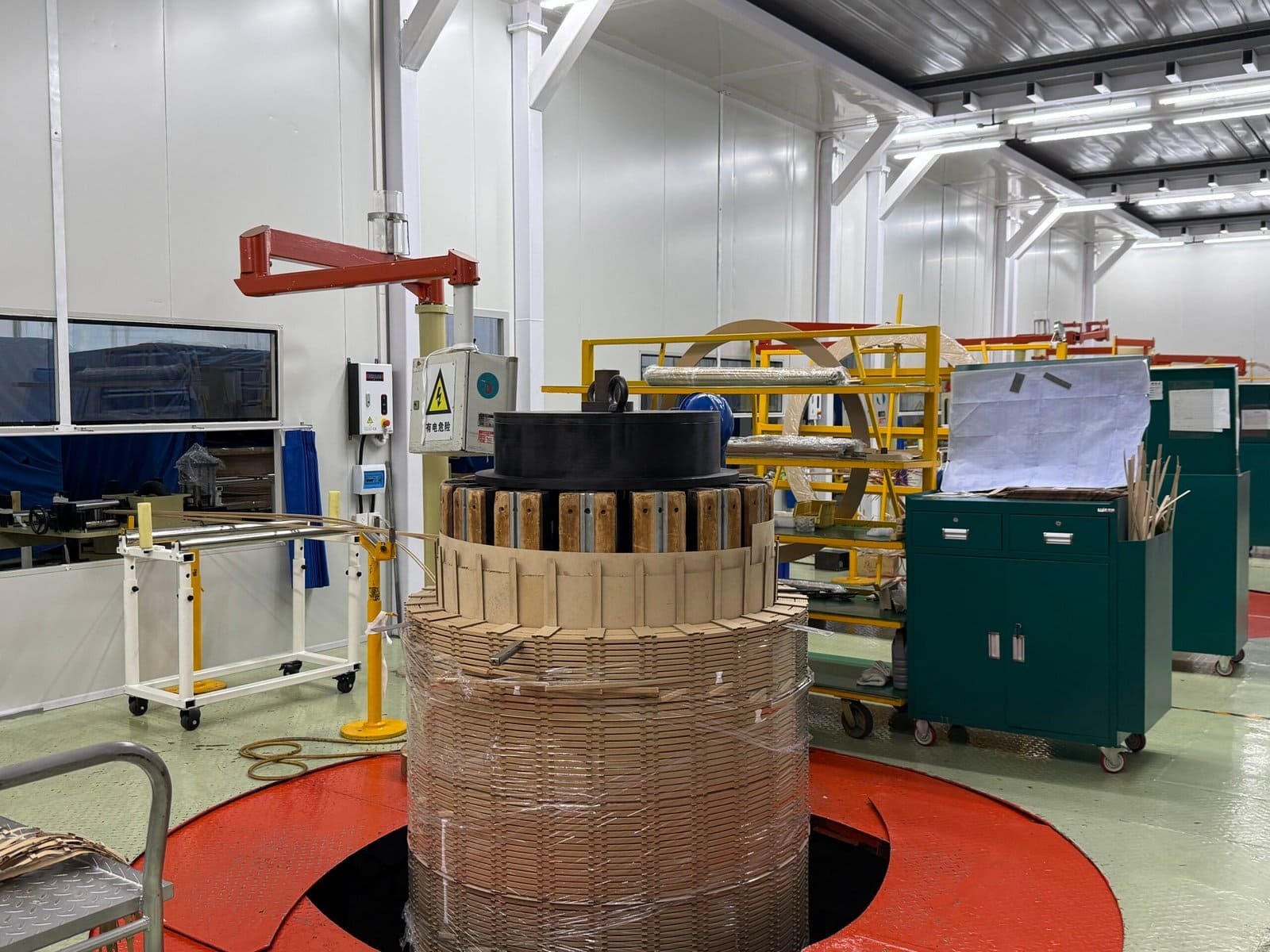
The transformer core is one of the most important components of a transformer, serving as the magnetic pathway that enables efficient energy transfer between the primary and secondary windings. Without a properly designed core, the transformer would require significantly more current to establish magnetic flux, resulting in poor efficiency, excessive losses, and impractical operation. The core concentrates and guides magnetic flux generated by the primary winding, ensuring that most of the magnetic field links both windings and participates in the energy conversion process.
Because transformers operate continuously in power generation, transmission, distribution, industrial, and commercial applications, the design and material selection of the core have a major influence on efficiency, temperature rise, noise levels, reliability, and operating costs throughout the transformer's lifespan.
The primary function of the transformer core is to provide a low-reluctance magnetic path for flux generated by the primary winding, allowing efficient electromagnetic induction between windings. The core improves magnetic coupling, reduces magnetizing current, minimizes losses, and enhances overall transformer efficiency.
The transformer core mainly provides mechanical support for the windings, while electrical energy transfer occurs independently of the core.False
The transformer core is essential for providing a controlled magnetic path that enables efficient electromagnetic induction and energy transfer between the primary and secondary windings.
Understanding the Role of the Transformer Core
A transformer operates based on the principle of electromagnetic induction.
When alternating current flows through the primary winding, it creates a changing magnetic field. The transformer core channels this magnetic flux so that it efficiently links the secondary winding and induces a voltage.
Main functions of the transformer core
| Function | Purpose |
|---|---|
| Magnetic flux path | Guides magnetic flux |
| Magnetic coupling | Links primary and secondary windings |
| Loss reduction | Improves efficiency |
| Structural support | Supports winding assembly |
| Noise reduction | Helps control vibration |
The magnetic role of the core is far more significant than its structural role.
How the Core Enables Electromagnetic Induction
Electromagnetic induction is the fundamental operating principle of transformers.
The changing magnetic flux generated by the primary winding induces voltage in the secondary winding according to Faraday's Law.
Energy transfer process
- Alternating current enters the primary winding.
- A varying magnetic field is created.
- The core directs magnetic flux.
- Flux links the secondary winding.
- Voltage is induced in the secondary winding.
- Electrical energy is delivered to the load.
Without an effective magnetic path, this process would be highly inefficient.
Why a Magnetic Core Is Necessary
Air can conduct magnetic flux, but it offers much higher magnetic resistance than specialized core materials.
Comparison of magnetic paths
| Medium | Magnetic Performance |
|---|---|
| Air | Poor |
| Silicon steel core | Excellent |
| Amorphous metal core | Superior |
Using a magnetic core dramatically improves flux concentration and transformer efficiency.
Providing a Low-Reluctance Flux Path
In magnetic circuits, reluctance is similar to resistance in electrical circuits.
A low-reluctance path allows magnetic flux to flow more easily.
Benefits of low reluctance
- Reduced magnetizing current
- Improved coupling efficiency
- Lower losses
- Better voltage regulation
Core materials are specifically selected to minimize magnetic reluctance.
Improving Magnetic Coupling
Magnetic coupling refers to how effectively magnetic flux generated by one winding links the other winding.
Strong coupling provides
| Benefit | Impact |
|---|---|
| Higher efficiency | Lower losses |
| Better voltage regulation | Stable output voltage |
| Reduced leakage flux | Improved performance |
The transformer core plays a central role in maximizing magnetic coupling.
Reducing Magnetizing Current
A transformer requires a small current to establish magnetic flux.
This is called magnetizing current.
Effect of a high-quality core
| Condition | Result |
|---|---|
| Efficient core | Lower magnetizing current |
| Poor magnetic path | Higher magnetizing current |
Reducing magnetizing current improves overall efficiency.
Supporting Voltage Transformation
The core enables the magnetic flux necessary for voltage conversion.
The relationship between primary and secondary voltages depends on winding turns and magnetic flux.
Voltage relationship
[\frac{V_p}{V_s}=\frac{N_p}{N_s}]
Where:
- (V_p) = Primary voltage
- (V_s) = Secondary voltage
- (N_p) = Primary turns
- (N_s) = Secondary turns
The core ensures efficient transfer of magnetic flux between these windings.
Minimizing Leakage Flux
Not all magnetic flux generated by the primary winding reaches the secondary winding.
Flux that does not contribute to energy transfer is called leakage flux.
Consequences of excessive leakage flux
| Effect | Impact |
|---|---|
| Reduced efficiency | Higher losses |
| Poor voltage regulation | Performance issues |
| Additional heating | Reduced lifespan |
Core design helps minimize leakage flux.
Reducing No-Load Losses
Even when a transformer carries no load, the core experiences losses.
Main core losses
| Loss Type | Cause |
|---|---|
| Hysteresis loss | Repeated magnetization cycles |
| Eddy current loss | Induced currents within the core |
Modern core materials are designed to minimize these losses.
Hysteresis Loss and Core Function
Magnetic domains within the core continuously realign as AC voltage alternates.
This process consumes energy.
Factors affecting hysteresis loss
- Core material quality
- Magnetic flux density
- Operating frequency
Advanced core materials significantly reduce hysteresis losses.
Eddy Current Loss and Core Construction
Changing magnetic fields induce currents within the core itself.
These unwanted currents generate heat.
Loss reduction methods
| Method | Benefit |
|---|---|
| Thin laminations | Reduced eddy currents |
| Insulation between laminations | Lower losses |
| High-resistivity materials | Improved efficiency |
Most transformer cores use laminated construction for this reason.
Providing Mechanical Support
Although magnetic performance is the primary function, the core also contributes structurally.
Structural functions
- Supports windings
- Maintains alignment
- Resists mechanical forces
- Provides assembly stability
This becomes particularly important during short-circuit events.
Influence on Transformer Efficiency
Core design directly affects transformer efficiency.
Relationship
| Core Characteristic | Efficiency Impact |
|---|---|
| High permeability | Improved efficiency |
| Low hysteresis loss | Reduced no-load loss |
| Low eddy current loss | Lower heating |
Core improvements often produce significant lifecycle energy savings.
Impact on Temperature Rise
Core losses eventually become heat.
Lower core losses result in
- Reduced operating temperature
- Improved cooling performance
- Extended insulation life
- Better reliability
Temperature management begins with efficient core design.
Influence on Noise and Vibration
Magnetic forces within the core cause vibration.
Common sources
- Magnetostriction
- Flux density variations
- Core joint movement
High-quality core construction reduces audible transformer noise.
Core Materials Used in Transformers
Different materials provide different performance characteristics.
Common core materials
| Material | Typical Application |
|---|---|
| Grain-oriented silicon steel | Most power transformers |
| Amorphous metal | High-efficiency distribution transformers |
| Nanocrystalline alloys | Specialized applications |
Material selection greatly influences performance.
Grain-Oriented Silicon Steel Cores
Grain-oriented silicon steel (GOES) is the industry standard.
Advantages
- High permeability
- Low core loss
- Good mechanical strength
- Proven reliability
Most modern power transformers use GOES cores.
Amorphous Metal Cores
Amorphous metal offers exceptionally low core losses.
Benefits
| Benefit | Result |
|---|---|
| Lower hysteresis loss | Improved efficiency |
| Reduced no-load losses | Lower operating costs |
| Better environmental performance | Reduced emissions |
Amorphous-core transformers are increasingly used where energy efficiency is a priority.
Core Configurations
Transformers utilize different core arrangements depending on application requirements.
Common configurations
| Configuration | Characteristics |
|---|---|
| Core-type | Widely used in distribution transformers |
| Shell-type | Strong mechanical design |
| Toroidal | High efficiency and low noise |
Each configuration offers unique advantages.
Core-Type Transformers
In a core-type transformer:
- Windings surround the core limbs.
- Flux follows a relatively simple path.
- Manufacturing is straightforward.
This design is common in utility and industrial transformers.
Shell-Type Transformers
In a shell-type transformer:
- Core surrounds the windings.
- Leakage flux is reduced.
- Mechanical strength is enhanced.
These transformers are often used for high-power applications.
Toroidal Cores
Toroidal transformers feature a ring-shaped core.
Advantages
- Very low leakage flux
- High efficiency
- Compact design
- Reduced noise
They are frequently used in electronic and specialty applications.
Role During Fault Conditions
The core must withstand abnormal operating conditions.
Challenges include
| Condition | Impact |
|---|---|
| Short circuits | High electromagnetic forces |
| Overexcitation | Increased flux density |
| Harmonics | Additional heating |
Robust core design supports reliable operation during disturbances.
Modern Developments in Core Technology
Current innovations focus on:
- Ultra-low-loss materials
- Improved lamination techniques
- Advanced joint designs
- Reduced noise emissions
- Enhanced sustainability
These advances continue to improve transformer performance worldwide.
Importance for Lifecycle Cost
Core losses occur continuously whenever the transformer is energized.
Long-term implications
| Factor | Impact |
|---|---|
| Energy consumption | Operating cost |
| Heat generation | Cooling requirements |
| Carbon emissions | Environmental performance |
Even small reductions in core loss can produce substantial savings over decades of operation.
How Do the Windings Transfer Electrical Energy?
Transformer windings are the electrical components responsible for transferring energy from one circuit to another through electromagnetic induction. While the transformer core provides the magnetic pathway, the windings generate and receive the magnetic flux that enables voltage transformation and power transfer. The interaction between the primary and secondary windings allows electrical energy to be transferred efficiently without any direct electrical connection between the circuits.
In modern power systems, transformer windings are carefully engineered to withstand electrical, thermal, and mechanical stresses while maintaining high efficiency and reliability. Their design directly affects transformer capacity, voltage regulation, losses, insulation performance, and operational lifespan.
Transformer windings transfer electrical energy by converting electrical energy into magnetic energy in the primary winding and then converting that magnetic energy back into electrical energy in the secondary winding through electromagnetic induction. This process enables efficient voltage transformation and electrical isolation between circuits.
Electrical energy flows directly from the primary winding to the secondary winding through physical conductor contact inside the transformer.False
Primary and secondary windings are electrically isolated from each other. Energy transfer occurs through electromagnetic induction using the magnetic flux created within the transformer core.
Understanding the Role of Transformer Windings
Every transformer contains at least two windings.
Main winding types
| Winding | Function |
|---|---|
| Primary winding | Receives input electrical power |
| Secondary winding | Delivers output electrical power |
The windings work together with the core to transfer energy efficiently.
What Is the Primary Winding?
The primary winding is connected to the incoming power source.
Primary winding functions
- Receives input voltage
- Draws magnetizing current
- Produces magnetic flux
- Initiates energy transfer
When alternating current flows through the primary winding, a changing magnetic field is created around the conductor.
What Is the Secondary Winding?
The secondary winding receives energy through magnetic coupling.
Secondary winding functions
| Function | Purpose |
|---|---|
| Receives magnetic flux | Enables induction |
| Produces output voltage | Supplies load |
| Delivers electrical power | Supports external circuits |
The secondary winding converts magnetic energy back into usable electrical energy.
The Energy Transfer Process
Transformer energy transfer occurs in several stages.
Step-by-step operation
- AC voltage is applied to the primary winding.
- Current flows through the primary winding.
- A changing magnetic field is created.
- Magnetic flux travels through the transformer core.
- Flux links the secondary winding.
- Voltage is induced in the secondary winding.
- Power is delivered to the connected load.
This process occurs continuously and almost instantaneously.
How Alternating Current Creates Magnetic Flux
When alternating current flows through a conductor, it produces a changing magnetic field.
The magnetic field continuously expands and collapses as the current alternates.
Relationship between current and magnetic field
- Increasing current produces increasing flux.
- Decreasing current reduces flux.
- Alternating current creates continuously changing flux.
This changing flux is the foundation of transformer operation.
Electromagnetic Induction and Energy Transfer
The operation of transformer windings is based on electromagnetic induction.
According to Faraday's Law, a changing magnetic flux induces voltage in a nearby conductor.
The induced voltage depends on:
- Number of turns
- Rate of flux change
- Magnetic coupling effectiveness
This principle allows energy transfer without direct electrical contact.
Why Windings Do Not Need Physical Contact
One of the most important characteristics of a transformer is electrical isolation.
Benefits of isolation
| Advantage | Description |
|---|---|
| Improved safety | Circuits remain separated |
| Voltage conversion | Different voltage levels possible |
| Fault protection | Reduced fault propagation |
| Grounding flexibility | Easier system design |
The windings transfer energy magnetically rather than electrically.
The Role of Magnetic Flux
Magnetic flux serves as the link between the windings.
Flux pathway
| Stage | Process |
|---|---|
| Primary winding | Generates flux |
| Core | Guides flux |
| Secondary winding | Receives flux |
Without magnetic flux, no energy transfer would occur.
How the Core Supports Energy Transfer
Although the windings create and receive magnetic fields, the core significantly improves efficiency.
Core contributions
- Concentrates magnetic flux
- Reduces magnetic reluctance
- Improves coupling
- Minimizes leakage flux
This enables more effective interaction between the windings.
Voltage Transformation Through Windings
The ratio of primary turns to secondary turns determines voltage transformation.
Voltage relationship
Where:
- (V_p) = Primary voltage
- (V_s) = Secondary voltage
- (N_p) = Primary turns
- (N_s) = Secondary turns
This relationship allows transformers to step voltage up or down.
Step-Up Transformer Operation
In a step-up transformer:
| Parameter | Condition |
|---|---|
| Secondary turns | Greater than primary turns |
| Output voltage | Higher |
| Output current | Lower |
These transformers are commonly used in power generation systems.
Step-Down Transformer Operation
In a step-down transformer:
| Parameter | Condition |
|---|---|
| Secondary turns | Fewer than primary turns |
| Output voltage | Lower |
| Output current | Higher |
Most distribution transformers operate in this manner.
Power Transfer Between Windings
Ideally, transformer power remains nearly constant.
Power relationship
Where:
- (P) = Power
- (V) = Voltage
- (I) = Current
As voltage changes, current adjusts correspondingly to maintain power transfer.
How Load Affects the Windings
When a load is connected to the secondary winding:
Sequence of events
- Secondary current begins to flow.
- Secondary magnetic field develops.
- Primary current increases automatically.
- Additional energy is transferred.
The transformer responds dynamically to changing load conditions.
Mutual Induction Between Windings
The interaction between primary and secondary windings is called mutual induction.
Characteristics
| Feature | Benefit |
|---|---|
| Magnetic coupling | Efficient energy transfer |
| Electrical isolation | Improved safety |
| Voltage transformation | Flexible operation |
Mutual induction is the core mechanism behind transformer functionality.
Importance of Coupling Efficiency
Not all magnetic flux links both windings.
Types of flux
| Flux Type | Role |
|---|---|
| Mutual flux | Transfers energy |
| Leakage flux | Does not transfer energy |
High-quality winding design maximizes mutual flux and minimizes leakage flux.
Leakage Flux and Performance
Leakage flux reduces energy transfer effectiveness.
Consequences
- Reduced efficiency
- Voltage regulation issues
- Additional losses
- Increased heating
Proper winding placement helps reduce leakage flux.
Winding Arrangement and Energy Transfer
The physical arrangement of windings strongly influences performance.
Design objectives
- Maximize magnetic coupling
- Reduce losses
- Improve cooling
- Enhance mechanical strength
Modern transformers use sophisticated winding configurations to achieve these goals.
Common Winding Configurations
Cylindrical windings
Used in many distribution transformers.
Advantages include:
- Simple construction
- Effective cooling
- Reliable operation
Disc windings
Common in large power transformers.
Benefits include:
- Improved voltage distribution
- Better impulse performance
- Enhanced cooling
Conductor Materials and Energy Transfer
The conductor material affects electrical losses during power transfer.
Common materials
| Material | Characteristics |
|---|---|
| Copper | High conductivity |
| Aluminum | Lower weight and cost |
Lower conductor resistance improves energy transfer efficiency.
Copper Losses During Energy Transfer
As current flows through the windings, some energy is lost as heat.
Copper loss relationship
These losses represent the primary load-dependent losses within a transformer.
Thermal Effects on Winding Performance
Winding temperature directly affects efficiency.
Higher temperatures cause
| Effect | Impact |
|---|---|
| Increased resistance | Higher losses |
| Insulation stress | Reduced lifespan |
| Reduced efficiency | Increased operating costs |
Effective cooling helps maintain optimal performance.
Electrical Isolation and Safety
The separation between primary and secondary windings provides important safety benefits.
Isolation advantages
- Prevents direct electrical connection
- Limits fault propagation
- Improves system protection
- Supports different grounding schemes
Transformer windings achieve both energy transfer and electrical isolation simultaneously.
Short-Circuit Forces on Windings
Fault conditions can generate extremely high mechanical forces.
Force relationship
Current increases dramatically during faults, creating strong electromagnetic stresses.
Design requirements
- Mechanical reinforcement
- Proper clamping
- Robust conductor support
These features help preserve winding integrity during disturbances.
Influence on Transformer Efficiency
Winding performance strongly affects overall transformer efficiency.
Factors influencing efficiency
| Factor | Effect |
|---|---|
| Conductor resistance | Loss generation |
| Winding geometry | Coupling effectiveness |
| Cooling performance | Temperature control |
| Insulation quality | Reliability |
Well-designed windings maximize energy transfer efficiency.
Modern Innovations in Winding Technology
Current developments include:
- Continuously transposed conductors (CTC)
- Improved insulation systems
- Advanced cooling channels
- Computer-optimized winding layouts
- Enhanced short-circuit withstand designs
These technologies improve efficiency, reliability, and lifespan.
Energy Transfer in Three-Phase Transformers
Three-phase transformers contain three sets of primary and secondary windings.
Benefits
| Advantage | Description |
|---|---|
| Higher capacity | Greater power transfer |
| Improved efficiency | Reduced material requirements |
| Better system integration | Utility applications |
The energy transfer principle remains the same as in single-phase transformers.
Relationship Between Windings and Transformer Rating
Transformer capacity is closely linked to winding design.
Rating considerations
- Current carrying capability
- Temperature rise limits
- Insulation strength
- Cooling effectiveness
Proper winding design ensures safe operation at rated power levels.
What Role Does Transformer Oil Play in Insulation and Cooling?

Transformer oil is one of the most critical components in oil-immersed transformers, serving both as an electrical insulating medium and an efficient cooling agent. While the transformer core and windings perform the primary task of transferring electrical energy, transformer oil ensures that these components can operate safely, efficiently, and reliably under varying load conditions. Without transformer oil, high-voltage insulation would be compromised, heat removal would be significantly reduced, and transformer lifespan would be dramatically shortened.
Modern transformer oils are specially formulated to provide excellent dielectric strength, thermal conductivity, chemical stability, and resistance to aging. Their condition directly influences transformer performance, reliability, maintenance requirements, and service life.
Transformer oil performs two essential functions: it provides electrical insulation between energized components and efficiently transfers heat away from the core and windings. By combining dielectric protection with cooling capability, transformer oil enables safe operation, improves efficiency, and extends transformer lifespan.
Transformer oil is used primarily for lubrication, while insulation and cooling are handled by other transformer components.False
Transformer oil's primary functions are electrical insulation and heat dissipation. It is not used as a lubricant in normal transformer operation.
Why Transformer Oil Is Necessary
Oil-immersed transformers operate under high electrical and thermal stresses.
Key operational challenges
| Challenge | Requirement |
|---|---|
| High voltage | Reliable insulation |
| Heat generation | Effective cooling |
| Long service life | Stable operating environment |
| Fault protection | Dielectric integrity |
Transformer oil helps address all these requirements simultaneously.
Understanding the Dual Function of Transformer Oil
Transformer oil serves two major purposes.
Primary functions
| Function | Purpose |
|---|---|
| Electrical insulation | Prevents electrical breakdown |
| Cooling medium | Removes internally generated heat |
These functions work together to maintain transformer reliability.
Role of Transformer Oil in Electrical Insulation
The oil fills the spaces between energized components and grounded parts.
Insulated components include
- Windings
- Core structures
- Leads and connections
- Tap changers
- Bushings
The oil prevents unwanted electrical discharge between these components.
Dielectric Strength of Transformer Oil
Dielectric strength measures the oil's ability to withstand electrical stress without breakdown.
Importance
| Characteristic | Benefit |
|---|---|
| High dielectric strength | Improved insulation |
| Electrical stability | Reliable operation |
| Breakdown resistance | Reduced fault risk |
High-quality transformer oil provides excellent insulation performance.
Preventing Electrical Arcing
Electrical arcing can severely damage transformer components.
Oil helps by
- Separating energized conductors
- Suppressing electrical discharges
- Maintaining dielectric integrity
- Reducing flashover risk
This protection becomes increasingly important at higher voltages.
Insulation Between Windings
The primary and secondary windings operate at different voltage levels.
Oil insulation supports
| Function | Result |
|---|---|
| Voltage separation | Safe operation |
| Electrical isolation | Improved reliability |
| Dielectric protection | Reduced failure risk |
The oil complements solid insulation materials within the transformer.
Supporting Solid Insulation Systems
Transformer oil works together with solid insulation materials such as:
- Kraft paper
- Pressboard
- Cellulose insulation
- Insulating spacers
Combined benefits
- Higher dielectric strength
- Improved reliability
- Better thermal performance
This combination forms the transformer's overall insulation system.
Heat Generation Inside Transformers
Every transformer generates heat during operation.
Main heat sources
| Source | Cause |
|---|---|
| Core losses | Hysteresis and eddy currents |
| Copper losses | Current flow in windings |
| Stray losses | Leakage flux effects |
Without cooling, temperatures would rise to unsafe levels.
Cooling Function of Transformer Oil
Transformer oil acts as a heat transfer medium.
Cooling process
- Windings generate heat.
- Oil absorbs thermal energy.
- Heated oil rises naturally.
- Heat transfers to radiators.
- Cooler oil returns to the windings.
This continuous cycle removes excess heat.
Heat Transfer Mechanism
Transformer oil transfers heat through convection.
Natural circulation process
| Stage | Description |
|---|---|
| Heating | Oil absorbs heat |
| Expansion | Warm oil becomes less dense |
| Upward movement | Hot oil rises |
| Cooling | Heat dissipates through radiators |
| Return flow | Cool oil sinks |
This natural circulation is fundamental to transformer cooling.
Oil and Temperature Control
Effective temperature control improves transformer performance.
Benefits
- Reduced insulation aging
- Improved efficiency
- Increased loading capability
- Enhanced reliability
Oil plays a central role in maintaining acceptable operating temperatures.
Impact on Insulation Life
Temperature is the primary factor affecting insulation aging.
Temperature effects
| Temperature Condition | Impact |
|---|---|
| Normal operation | Expected lifespan |
| Elevated temperature | Accelerated aging |
| Severe overheating | Rapid deterioration |
Efficient oil cooling helps maximize insulation life.
Relationship Between Oil and Transformer Efficiency
Heat affects electrical resistance.
As winding temperature rises:
- Resistance increases
- Copper losses increase
- Efficiency decreases
Proper oil cooling helps minimize these effects.
Types of Transformer Oil
Several oil types are used in modern transformers.
Common categories
| Oil Type | Characteristics |
|---|---|
| Mineral oil | Most widely used |
| Natural ester oil | Biodegradable |
| Synthetic ester oil | High fire safety |
| Silicone fluid | Specialized applications |
Selection depends on technical, environmental, and safety requirements.
Mineral Transformer Oil
Mineral oil remains the industry standard.
Advantages
- Good dielectric strength
- Effective cooling
- Proven performance
- Economical cost
Most utility transformers worldwide use mineral oil.
Natural Ester Fluids
Natural ester oils are derived from vegetable-based sources.
Benefits
| Advantage | Impact |
|---|---|
| Biodegradable | Environmental protection |
| High flash point | Improved fire safety |
| Moisture tolerance | Better insulation preservation |
These fluids are increasingly used in environmentally sensitive areas.
Synthetic Ester Fluids
Synthetic esters provide enhanced fire performance.
Typical applications
- Buildings
- Tunnels
- Offshore facilities
- Critical infrastructure
Their high fire point makes them suitable for locations with strict safety requirements.
Cooling Methods Utilizing Transformer Oil
Oil participates in several standardized cooling systems.
Common cooling classifications
| Method | Description |
|---|---|
| ONAN | Oil Natural Air Natural |
| ONAF | Oil Natural Air Forced |
| OFAF | Oil Forced Air Forced |
| OFWF | Oil Forced Water Forced |
Each method uses transformer oil as the primary heat transfer medium.
Oil Natural Air Natural (ONAN)
ONAN is the most common cooling arrangement.
Characteristics
- Natural oil circulation
- Natural air cooling
- Simple design
- High reliability
Suitable for many distribution and power transformers.
Oil Natural Air Forced (ONAF)
ONAF uses cooling fans to improve heat removal.
Benefits
| Benefit | Result |
|---|---|
| Increased cooling capacity | Higher loading capability |
| Reduced temperatures | Improved lifespan |
| Better overload performance | Greater flexibility |
Many power transformers employ ONAF cooling.
Oil Forced Air Forced (OFAF)
Large transformers often require active oil circulation.
Features
- Oil pumps
- Forced oil movement
- Enhanced heat transfer
- Improved cooling efficiency
This method supports higher transformer ratings.
Oil Quality and Performance
Oil condition directly influences insulation and cooling performance.
Critical oil properties
| Property | Importance |
|---|---|
| Dielectric strength | Insulation capability |
| Moisture content | Electrical reliability |
| Acidity | Aging indicator |
| Viscosity | Cooling effectiveness |
Regular testing is essential.
Moisture Contamination
Water is one of the most harmful contaminants in transformer oil.
Effects
- Reduced dielectric strength
- Increased insulation aging
- Higher failure risk
Moisture control is a major maintenance objective.
Oxidation and Oil Aging
Transformer oil gradually degrades over time.
Causes
- Oxygen exposure
- Elevated temperatures
- Electrical stress
Consequences
| Effect | Result |
|---|---|
| Sludge formation | Reduced cooling |
| Increased acidity | Insulation damage |
| Reduced dielectric strength | Higher fault risk |
Monitoring oil condition helps prevent these problems.
Dissolved Gas Formation
Electrical and thermal faults can generate gases within transformer oil.
Common fault gases
| Gas | Possible Cause |
|---|---|
| Hydrogen | Partial discharge |
| Methane | Low-temperature overheating |
| Ethylene | High-temperature overheating |
| Acetylene | Arcing |
These gases provide valuable diagnostic information.
Dissolved Gas Analysis (DGA)
DGA is one of the most important transformer monitoring techniques.
Purposes
- Fault detection
- Condition assessment
- Maintenance planning
- Reliability improvement
Oil serves as both an insulating medium and a diagnostic resource.
Oil's Role During Fault Conditions
Transformer oil contributes to fault management.
Functions
- Suppresses electrical arcs
- Disperses fault-generated heat
- Helps prevent catastrophic damage
These characteristics improve transformer resilience.
Fire Safety Considerations
Different oil types provide different levels of fire resistance.
Comparison
| Fluid Type | Fire Performance |
|---|---|
| Mineral oil | Standard |
| Natural ester | Improved |
| Synthetic ester | Excellent |
Fire safety often influences fluid selection.
Environmental Considerations
Environmental concerns increasingly affect transformer oil choices.
Factors considered
- Biodegradability
- Spill containment
- Fire risk
- Regulatory compliance
Natural ester fluids are becoming more popular in environmentally sensitive applications.
Impact on Transformer Lifespan
Effective insulation and cooling directly influence service life.
Benefits of healthy oil
| Benefit | Impact |
|---|---|
| Better cooling | Lower temperatures |
| Strong insulation | Fewer failures |
| Reduced aging | Longer lifespan |
| Improved reliability | Lower maintenance costs |
Oil condition is closely linked to transformer longevity.
Monitoring Transformer Oil
Routine oil monitoring typically includes:
- Dielectric strength testing
- Moisture analysis
- Acidity testing
- Dissolved gas analysis
- Interfacial tension measurement
These tests provide valuable insight into transformer health.
Modern Developments in Transformer Fluids
Current innovations include:
- High-temperature ester fluids
- Environmentally friendly insulating liquids
- Advanced oxidation inhibitors
- Improved monitoring technologies
- Enhanced fire-resistant formulations
These developments continue to improve transformer performance and sustainability.
How Do the Tank and Cooling System Support Transformer Operation?
The transformer tank and cooling system are essential components that ensure the safe, reliable, and efficient operation of oil-immersed transformers. While the core and windings perform the electrical energy conversion process, the tank provides mechanical protection and containment, while the cooling system manages the heat generated during operation. Together, these components protect internal transformer parts from environmental exposure, maintain insulation integrity, control operating temperatures, and extend equipment lifespan.
In modern power systems, transformers are expected to operate continuously for decades under varying load and environmental conditions. Without a properly designed tank and cooling system, excessive temperatures, insulation degradation, moisture ingress, and mechanical damage could significantly reduce reliability and service life.
The transformer tank supports operation by housing and protecting the core, windings, and insulating oil, while the cooling system removes heat generated by electrical losses. Together, they maintain safe operating temperatures, preserve insulation performance, prevent contamination, and ensure long-term transformer reliability and efficiency.
The transformer tank serves only as an external enclosure, while cooling and operational reliability depend entirely on internal electrical components.False
The tank provides critical structural support, oil containment, environmental protection, and integration of cooling equipment. It plays a major role in maintaining transformer performance and reliability.
Why the Tank and Cooling System Are Essential
Every transformer generates heat during operation due to electrical losses.
Main operational challenges
| Challenge | Required Solution |
|---|---|
| Heat generation | Effective cooling |
| Environmental exposure | Protective enclosure |
| Insulation preservation | Oil containment |
| Mechanical protection | Structural support |
The tank and cooling system address all of these requirements.
Primary Functions of the Transformer Tank
The tank serves as the main structural enclosure of an oil-immersed transformer.
Key functions
| Function | Purpose |
|---|---|
| Oil containment | Stores insulating fluid |
| Mechanical protection | Protects internal components |
| Environmental isolation | Prevents contamination |
| Structural support | Holds transformer assembly |
| Cooling integration | Supports radiators and accessories |
The tank is far more than a simple housing.
Housing the Active Part
The active part of a transformer consists primarily of:
- Core
- Windings
- Insulation structures
- Internal leads
- Tap changer connections
The tank securely contains and protects these components.
Providing Mechanical Protection
Transformers are exposed to various mechanical stresses throughout their service life.
Sources of stress
- Transportation
- Installation activities
- Short-circuit forces
- Seismic events
- Wind loads
The tank provides structural strength to withstand these conditions.
Oil Containment Function
Transformer oil performs both cooling and insulation functions.
Tank responsibilities
| Requirement | Importance |
|---|---|
| Leak prevention | Maintain oil level |
| Contamination prevention | Preserve oil quality |
| Long-term integrity | Reliable operation |
Proper oil containment is critical to transformer health.
Environmental Protection
The tank isolates internal components from the external environment.
Protection against
- Moisture
- Dust
- Salt contamination
- Industrial pollutants
- Rain and snow
Environmental protection helps preserve insulation integrity and reliability.
Moisture Exclusion
Moisture is one of the most harmful contaminants in transformers.
Effects of moisture ingress
| Problem | Consequence |
|---|---|
| Reduced dielectric strength | Higher failure risk |
| Accelerated insulation aging | Shorter lifespan |
| Increased partial discharge risk | Reliability concerns |
A properly sealed tank minimizes these risks.
Structural Design of Transformer Tanks
Tank construction varies depending on transformer size and application.
Common design considerations
- Mechanical strength
- Thermal performance
- Corrosion resistance
- Transportation requirements
- Maintenance accessibility
The design must balance durability, cost, and performance.
Materials Used for Transformer Tanks
Most transformer tanks are fabricated from steel.
Common materials
| Material | Characteristics |
|---|---|
| Carbon steel | High strength, economical |
| Stainless steel | Corrosion resistance |
| Special alloys | Specialized environments |
Material selection depends on operating conditions and project requirements.
Tank Shapes and Configurations
Transformer tanks may be designed in various forms.
Common configurations
| Configuration | Typical Application |
|---|---|
| Rectangular tank | Power transformers |
| Corrugated tank | Distribution transformers |
| Conservator-type tank | Large oil-filled units |
Each design provides unique operational benefits.
Corrugated Tank Design
Many distribution transformers utilize corrugated walls.
Advantages
- Increased cooling surface area
- Reduced need for radiators
- Simplified construction
- Compensation for oil expansion
Corrugated tanks combine structural and thermal functions.
Conservator Systems
Large transformers often use conservator tanks.
Purpose
- Accommodate oil expansion and contraction
- Reduce oil exposure to atmosphere
- Minimize oxidation
Conservators help maintain oil quality over long service periods.
Oil Expansion During Operation
Transformer oil expands as temperature rises.
Expansion effects
| Condition | Result |
|---|---|
| Increased temperature | Oil volume increases |
| Decreased temperature | Oil volume decreases |
Tank design must safely accommodate these volume changes.
Role of the Cooling System
The cooling system removes heat generated by transformer losses.
Heat sources
- Core losses
- Copper losses
- Stray losses
Without cooling, internal temperatures would reach damaging levels.
Why Temperature Control Matters
Transformer insulation life is highly temperature-dependent.
Elevated temperatures can cause
- Accelerated aging
- Reduced dielectric strength
- Increased losses
- Shortened service life
Effective cooling is essential for reliability.
Heat Generation Inside Transformers
Every watt of loss eventually becomes heat.
Typical loss categories
| Loss Type | Source |
|---|---|
| Core loss | Magnetic processes |
| Copper loss | Winding resistance |
| Stray loss | Leakage flux |
The cooling system must continuously remove this heat.
Basic Cooling Principle
The cooling system transfers heat from internal components to the surrounding environment.
Heat transfer path
- Heat generated in windings and core.
- Oil absorbs heat.
- Heated oil circulates.
- Heat transfers to cooling surfaces.
- Heat dissipates into surrounding air or water.
This process maintains acceptable operating temperatures.
Oil as a Cooling Medium
Transformer oil is an excellent heat transfer fluid.
Benefits
| Property | Advantage |
|---|---|
| Good thermal conductivity | Efficient heat transfer |
| Fluid circulation | Continuous cooling |
| Electrical insulation | Dual functionality |
Oil enables both cooling and insulation simultaneously.
Natural Oil Circulation
Many transformers rely on natural convection.
Process
- Hot oil rises
- Cooler oil sinks
- Continuous circulation develops
This natural movement transports heat without pumps.
Radiators and Heat Dissipation
Radiators increase the surface area available for cooling.
Functions
| Function | Benefit |
|---|---|
| Larger cooling area | Improved heat transfer |
| Natural airflow exposure | Better cooling |
| Enhanced thermal performance | Lower temperatures |
Radiators are common on medium and large transformers.
Oil Natural Air Natural (ONAN) Cooling
ONAN is the most widely used cooling method.
Characteristics
- Natural oil circulation
- Natural air cooling
- No moving parts
- High reliability
This method is common in both distribution and power transformers.
Oil Natural Air Forced (ONAF) Cooling
ONAF systems add cooling fans.
Advantages
| Benefit | Result |
|---|---|
| Increased airflow | Better cooling |
| Higher loading capability | Greater capacity |
| Reduced operating temperature | Longer life |
Fans significantly improve heat dissipation.
Oil Forced Air Forced (OFAF) Cooling
Larger transformers often require active oil circulation.
Features
- Oil pumps
- Forced oil movement
- Forced air cooling
This system provides greater cooling capability than natural circulation alone.
Oil Forced Water Forced (OFWF) Cooling
Very large transformers may use water-cooled heat exchangers.
Benefits
| Feature | Advantage |
|---|---|
| High cooling capacity | Supports large ratings |
| Compact installation | Reduced footprint |
| Efficient heat transfer | Lower temperatures |
OFWF cooling is common in power plants and industrial facilities.
Cooling System Components
Modern cooling systems include several key elements.
Major components
- Radiators
- Cooling fans
- Oil pumps
- Heat exchangers
- Temperature sensors
- Control systems
Each component contributes to thermal management.
Cooling System Controls
Cooling equipment often operates automatically.
Control objectives
- Maintain temperature limits
- Optimize energy consumption
- Improve reliability
- Reduce unnecessary wear
Automatic controls enhance operational efficiency.
Impact on Transformer Efficiency
Cooling directly influences efficiency.
Relationship
Higher temperatures cause:
- Increased conductor resistance
- Higher copper losses
- Reduced efficiency
Effective cooling minimizes these effects.
Influence on Transformer Lifespan
Temperature is one of the most important factors affecting lifespan.
Temperature effects
| Operating Condition | Expected Impact |
|---|---|
| Proper cooling | Maximum lifespan |
| Moderate overheating | Accelerated aging |
| Severe overheating | Premature failure |
Cooling systems protect long-term asset value.
Supporting Overload Capability
Effective cooling increases transformer loading flexibility.
Benefits
- Temporary overload capability
- Emergency operation support
- Improved asset utilization
Well-designed cooling systems provide valuable operational margins.
Tank and Cooling System Monitoring
Modern transformers include extensive monitoring capabilities.
Common measurements
| Parameter | Purpose |
|---|---|
| Oil temperature | Thermal assessment |
| Winding temperature | Insulation protection |
| Oil level | Fluid management |
| Cooling equipment status | Reliability monitoring |
Monitoring supports proactive maintenance.
Corrosion Protection
Tank integrity must be maintained throughout the transformer's life.
Protection methods
- Protective coatings
- Galvanization
- Corrosion-resistant materials
- Regular inspections
Corrosion control protects both structural and thermal performance.
Maintenance Requirements
Routine maintenance helps preserve tank and cooling system effectiveness.
Typical maintenance activities
- Leak inspections
- Radiator cleaning
- Fan testing
- Pump inspections
- Coating repairs
- Oil level verification
Regular maintenance supports long-term reliability.
Common Problems Associated With Tanks and Cooling Systems
Potential issues
| Problem | Consequence |
|---|---|
| Oil leaks | Reduced insulation and cooling |
| Fan failures | Elevated temperatures |
| Blocked radiators | Reduced heat transfer |
| Corrosion | Structural deterioration |
| Pump malfunctions | Poor oil circulation |
Early detection helps prevent major failures.
Modern Innovations
Recent developments include:
- Intelligent cooling controls
- Variable-speed fans
- Advanced corrosion-resistant coatings
- Online thermal monitoring
- Digital asset management systems
These technologies improve efficiency and reliability.
Contribution to Overall Transformer Performance
The tank and cooling system influence:
- Operating temperature
- Efficiency
- Reliability
- Safety
- Service life
- Maintenance costs
Their importance extends far beyond physical containment.
What Accessories and Protection Devices Are Essential for Safe Operation?
Transformer accessories and protection devices are critical components that ensure the safe, reliable, and efficient operation of power and distribution transformers. While the core, windings, insulation system, and cooling equipment perform the primary electrical functions, accessories and protective devices continuously monitor operating conditions, detect abnormal situations, provide early warning of developing faults, and initiate protective actions when necessary. Without these devices, even minor abnormalities could escalate into severe equipment damage, extended outages, safety hazards, or catastrophic transformer failures.
Modern transformers operate under varying electrical loads, environmental conditions, and system disturbances. Therefore, comprehensive protection and monitoring systems are essential to safeguard transformer assets, maintain system reliability, and minimize operational risks throughout the transformer's service life.
Transformer accessories and protection devices ensure safe operation by monitoring temperature, pressure, oil condition, oil level, gas generation, electrical faults, and cooling system performance. They provide early fault detection, alarm functions, automatic shutdown capabilities, and operational monitoring that protect both the transformer and the surrounding power system.
Transformer protection devices are only necessary during fault conditions and have little impact on day-to-day transformer operation.False
Many transformer accessories continuously monitor operating conditions and provide critical information that supports safe operation, preventive maintenance, fault detection, and long-term reliability.
Why Transformer Protection Is Important
Transformers represent significant capital investments and are often critical to power system operation.
Potential risks without protection
| Risk | Consequence |
|---|---|
| Overheating | Insulation damage |
| Internal faults | Catastrophic failure |
| Oil loss | Reduced cooling and insulation |
| Overpressure | Tank damage |
| Electrical faults | Service interruption |
Protection devices help prevent these issues from becoming major failures.
Categories of Transformer Accessories
Transformer accessories generally fall into several categories.
Main categories
| Category | Purpose |
|---|---|
| Monitoring devices | Condition assessment |
| Protective devices | Fault protection |
| Cooling accessories | Temperature control |
| Oil management equipment | Fluid monitoring |
| Operational accessories | Maintenance and operation support |
Together they form an integrated protection system.
Temperature Indicators
Temperature monitoring is essential because excessive heat is one of the primary causes of transformer aging.
Main temperature measurements
- Top-oil temperature
- Winding temperature
- Ambient temperature
Continuous monitoring helps ensure safe operation.
Oil Temperature Indicator (OTI)
The Oil Temperature Indicator measures the temperature of transformer oil.
Functions
| Function | Benefit |
|---|---|
| Temperature indication | Operational awareness |
| Alarm initiation | Early warning |
| Cooling control | Fan and pump activation |
The OTI is one of the most commonly installed transformer accessories.
Winding Temperature Indicator (WTI)
The WTI estimates or directly measures winding temperature.
Importance
- Protects insulation
- Detects overload conditions
- Supports thermal management
Winding temperature is often the most critical thermal parameter.
Temperature Alarms and Trips
Most transformers include programmable temperature thresholds.
Typical actions
| Condition | Response |
|---|---|
| Elevated temperature | Alarm |
| High temperature | Cooling activation |
| Critical temperature | Trip command |
These functions prevent severe overheating.
Buchholz Relay
The Buchholz relay is one of the most important protection devices for conservator-type oil-filled transformers.
Installation location
Between:
- Main tank
- Conservator tank
Functions
| Fault Condition | Response |
|---|---|
| Slow gas accumulation | Alarm |
| Sudden oil movement | Trip |
It provides early warning of internal faults.
How the Buchholz Relay Works
Internal faults often generate gases within transformer oil.
Examples
- Partial discharge
- Insulation breakdown
- Overheating
- Arcing
The Buchholz relay detects these gases before major damage occurs.
Gas Collection and Fault Detection
Gas generation frequently precedes transformer failure.
Common gases
| Gas | Possible Cause |
|---|---|
| Hydrogen | Partial discharge |
| Methane | Thermal fault |
| Ethylene | High-temperature overheating |
| Acetylene | Arcing |
The Buchholz relay helps identify developing problems at an early stage.
Pressure Relief Device (PRD)
Internal faults can generate dangerous pressure increases.
Purpose
- Prevent tank rupture
- Release excessive pressure
- Improve safety
The PRD protects the transformer during severe fault conditions.
Operation of the Pressure Relief Device
When internal pressure exceeds a preset level:
- The PRD opens.
- Pressure is released.
- Mechanical damage is prevented.
Many PRDs also provide alarm contacts.
Sudden Pressure Relay
Large transformers often include sudden pressure relays.
Function
Detect rapid pressure increases caused by:
- Internal arcing
- Severe faults
- Insulation failure
Rapid response helps minimize damage.
Oil Level Indicator
Maintaining proper oil level is critical for insulation and cooling.
Functions
| Function | Benefit |
|---|---|
| Visual oil level indication | Easy inspection |
| Low-level alarm | Early warning |
| Operational monitoring | Improved reliability |
Low oil levels require immediate investigation.
Conservator Oil Level Monitoring
Conservator-equipped transformers experience oil level changes as temperature varies.
Monitoring objectives
- Verify normal oil expansion
- Detect leaks
- Confirm proper oil inventory
Continuous monitoring supports reliable operation.
Magnetic Oil Gauge (MOG)
The Magnetic Oil Gauge provides a visual indication of conservator oil level.
Advantages
- Simple operation
- Reliable measurement
- Alarm capability
It is widely used in power transformers.
Oil Sampling Valve
Oil testing is a key component of transformer maintenance.
Sampling valve functions
- Collect oil samples
- Support laboratory testing
- Enable condition assessment
Oil analysis provides valuable diagnostic information.
Drain and Filling Valves
These accessories facilitate oil management activities.
Applications
| Activity | Purpose |
|---|---|
| Oil replacement | Maintenance |
| Oil filtration | Condition improvement |
| Oil filling | Commissioning |
Proper valve design simplifies maintenance procedures.
Dissolved Gas Analysis (DGA) Monitoring Systems
Modern transformers often include online DGA monitors.
Benefits
- Continuous fault detection
- Early warning capability
- Improved asset management
Online monitoring reduces dependence on periodic sampling.
Moisture Monitoring Systems
Water contamination can severely affect transformer insulation.
Monitoring objectives
- Detect moisture ingress
- Evaluate insulation condition
- Prevent dielectric deterioration
Moisture sensors improve reliability and maintenance planning.
Breather System
Transformers must accommodate oil expansion and contraction.
Breather functions
- Allow air exchange
- Prevent moisture ingress
- Protect oil quality
Breathers are especially important for conservator-type transformers.
Silica Gel Breather
The most common breather type uses silica gel.
Advantages
| Function | Benefit |
|---|---|
| Moisture absorption | Dry incoming air |
| Color indication | Easy condition assessment |
| Simple maintenance | Low operating cost |
Silica gel helps preserve oil quality.
Oil Preservation Systems
Advanced transformers often use enhanced preservation systems.
Common types
- Nitrogen blanket systems
- Rubber bladder systems
- Diaphragm conservators
These systems reduce oil oxidation and aging.
Cooling Fans
Cooling fans improve heat dissipation.
Functions
- Increase airflow
- Reduce operating temperature
- Increase transformer capacity
Fans are common in ONAF and OFAF cooling systems.
Oil Pumps
Large transformers often utilize oil pumps.
Benefits
| Benefit | Result |
|---|---|
| Improved circulation | Better cooling |
| Lower hot-spot temperatures | Longer insulation life |
| Increased load capability | Operational flexibility |
Oil pumps are essential in forced-cooling systems.
Fan and Pump Monitoring
Cooling equipment must operate reliably.
Monitored parameters
- Running status
- Motor condition
- Failure alarms
- Control performance
Cooling failures can quickly affect transformer health.
Current Transformers (CTs)
CTs provide electrical measurements and protection inputs.
Applications
| Application | Purpose |
|---|---|
| Differential protection | Internal fault detection |
| Overcurrent protection | Fault isolation |
| Monitoring | Load measurement |
CTs are fundamental components of transformer protection systems.
Differential Protection Relay
Differential protection is one of the most important electrical protection methods.
Operating principle
Compares:
- Incoming current
- Outgoing current
Significant differences indicate an internal fault.
Overcurrent Protection
Overcurrent relays protect transformers against excessive current levels.
Common causes
- Short circuits
- Equipment failures
- System disturbances
Fast fault isolation minimizes damage.
Earth Fault Protection
Ground faults can cause severe damage if not detected.
Functions
- Detect insulation failures
- Identify ground current paths
- Initiate protective actions
Ground fault protection enhances system safety.
Surge Arresters
Transformers are vulnerable to transient overvoltages.
Sources
| Source | Example |
|---|---|
| Lightning strikes | Atmospheric surges |
| Switching operations | Network transients |
Surge arresters protect insulation systems from damage.
Bushing Monitoring Systems
Bushings are critical insulation components.
Monitoring objectives
- Detect insulation deterioration
- Measure capacitance changes
- Identify developing faults
Bushing failures can be catastrophic if not detected early.
Online Condition Monitoring Systems
Modern digital substations increasingly utilize online monitoring.
Parameters monitored
| Parameter | Purpose |
|---|---|
| Temperature | Thermal assessment |
| Gas levels | Fault detection |
| Moisture | Insulation monitoring |
| Load current | Capacity management |
| Voltage | System performance |
These systems improve asset visibility and reliability.
Supervisory Control and Data Acquisition (SCADA)
SCADA systems integrate transformer monitoring into broader network management.
Benefits
- Remote monitoring
- Alarm management
- Historical analysis
- Operational optimization
SCADA improves decision-making and response times.
Intelligent Electronic Devices (IEDs)
Modern transformers often incorporate advanced digital protection systems.
Capabilities
- Fault analysis
- Event recording
- Communication integration
- Automated protection functions
IEDs enhance protection accuracy and flexibility.
Alarm and Trip Systems
Protection devices generally operate at multiple levels.
Typical sequence
| Condition | Action |
|---|---|
| Abnormal condition | Alarm |
| Severe condition | Trip |
| Critical fault | Emergency isolation |
This layered approach improves equipment protection.
Importance of Regular Testing
Protection devices must be tested periodically.
Testing objectives
- Verify functionality
- Confirm calibration
- Ensure reliability
- Detect hidden failures
Routine testing is essential for dependable protection.
Integration of Protection Systems
Modern transformer protection relies on coordinated operation.
Integrated functions
- Thermal protection
- Mechanical protection
- Electrical protection
- Condition monitoring
Together they provide comprehensive asset protection.
Benefits of Comprehensive Protection
Operational advantages
| Benefit | Impact |
|---|---|
| Early fault detection | Reduced damage |
| Improved reliability | Higher availability |
| Lower maintenance costs | Better economics |
| Enhanced safety | Personnel protection |
| Extended service life | Greater asset value |
Protection systems contribute significantly to transformer lifecycle performance.
How Do All Components Work Together to Ensure Reliable Performance?
A transformer is far more than a collection of individual parts. Reliable transformer operation depends on the coordinated interaction of the core, windings, insulation system, transformer oil, tank, cooling equipment, accessories, and protection devices. Each component performs a specific function, but no component operates independently. Instead, all parts work together as an integrated system to transfer electrical energy efficiently, maintain insulation integrity, control temperature, withstand electrical and mechanical stresses, and protect against abnormal operating conditions.
Whether in power generation, transmission, distribution, industrial facilities, renewable energy plants, or commercial buildings, transformer reliability depends on the health and performance of every major component. A weakness in any one area can affect the entire transformer and potentially lead to reduced efficiency, accelerated aging, or failure.
Reliable transformer performance is achieved through the coordinated operation of the core, windings, insulation system, cooling system, transformer oil, tank structure, monitoring devices, and protection equipment. Together, these components ensure efficient energy transfer, thermal stability, electrical insulation, mechanical integrity, fault protection, and long service life.
Each transformer component functions independently, so the failure or degradation of one component has minimal impact on overall transformer performance.False
Transformer components are highly interconnected. Problems affecting insulation, cooling, oil quality, windings, or protection systems can influence the performance, reliability, and lifespan of the entire transformer.
Understanding the Transformer as an Integrated System
A transformer operates through the interaction of multiple systems working simultaneously.
Major transformer subsystems
| Subsystem | Primary Function |
|---|---|
| Core system | Magnetic flux path |
| Winding system | Energy transfer |
| Insulation system | Electrical protection |
| Oil system | Cooling and insulation |
| Cooling system | Heat dissipation |
| Tank structure | Mechanical protection |
| Monitoring system | Condition assessment |
| Protection system | Fault prevention |
Reliable operation requires all subsystems to function properly.
The Core as the Magnetic Foundation
The transformer core forms the magnetic circuit that enables energy transfer.
Core responsibilities
- Concentrate magnetic flux
- Provide low-reluctance magnetic path
- Improve magnetic coupling
- Reduce magnetizing current
- Minimize no-load losses
Without an efficient core, transformer performance would be severely reduced.
How the Core Supports the Windings
The core and windings operate as a single electromagnetic system.
Interaction
- Primary winding receives AC power.
- Core channels magnetic flux.
- Secondary winding intercepts flux.
- Voltage is induced.
- Power is transferred to the load.
Efficient magnetic coupling depends on both the core and winding design.
Role of the Primary Winding
The primary winding initiates the energy transfer process.
Functions
| Function | Purpose |
|---|---|
| Receives input power | System energization |
| Creates magnetic flux | Core excitation |
| Responds to load demand | Power regulation |
Its performance directly affects transformer efficiency and stability.
Role of the Secondary Winding
The secondary winding delivers usable electrical energy.
Responsibilities
- Receive magnetic flux
- Produce output voltage
- Supply connected loads
- Maintain power transfer
The secondary winding converts magnetic energy back into electrical energy.
Electromagnetic Energy Transfer
The coordinated operation of the core and windings enables electromagnetic induction.
Energy conversion sequence
| Stage | Process |
|---|---|
| Electrical input | Primary winding |
| Magnetic conversion | Core flux |
| Electrical output | Secondary winding |
This continuous process forms the basis of transformer operation.
Importance of the Insulation System
Energy transfer occurs safely only when proper insulation exists between energized components.
Insulation functions
- Prevent electrical breakdown
- Separate voltage levels
- Protect against short circuits
- Maintain dielectric integrity
The insulation system supports every electrical function within the transformer.
Interaction Between Insulation and Windings
The windings operate under significant electrical stress.
Insulation protects
| Area | Protection Requirement |
|---|---|
| Turn-to-turn | Voltage isolation |
| Layer-to-layer | Dielectric protection |
| Winding-to-core | Ground insulation |
| Winding-to-tank | System isolation |
Reliable energy transfer depends on effective insulation.
Transformer Oil as a Dual-Purpose Medium
In oil-immersed transformers, transformer oil performs two critical roles.
Primary functions
| Function | Benefit |
|---|---|
| Insulation | Dielectric protection |
| Cooling | Heat transfer |
Oil connects the thermal and electrical systems of the transformer.
How Oil Supports the Insulation System
Transformer oil fills spaces around energized components.
Benefits
- Increased dielectric strength
- Suppression of partial discharge
- Reduced electrical stress
- Improved reliability
Oil and solid insulation operate together as a unified insulation system.
How Oil Supports Cooling
The core and windings generate heat continuously.
Oil cooling process
- Core and windings generate heat.
- Oil absorbs thermal energy.
- Heated oil circulates.
- Heat transfers to radiators.
- Cooler oil returns.
This cycle maintains acceptable operating temperatures.
The Tank as the Structural Backbone
The tank houses and protects all active transformer components.
Functions
| Function | Purpose |
|---|---|
| Structural support | Mechanical stability |
| Oil containment | Fluid management |
| Environmental protection | Contamination prevention |
| Equipment mounting | Cooling and accessory support |
The tank integrates multiple transformer systems into a single assembly.
Protecting Internal Components
The tank shields critical components from external influences.
Environmental threats
- Moisture
- Dust
- Salt contamination
- Industrial pollutants
- Weather exposure
Protection from these factors helps maintain long-term reliability.
Cooling Systems and Thermal Stability
Temperature control is one of the most important factors affecting transformer life.
Cooling objectives
- Remove heat
- Protect insulation
- Improve efficiency
- Support loading capability
The cooling system continuously interacts with the oil and active parts.
Heat Generation and Removal
Every transformer loss eventually becomes heat.
Major heat sources
| Source | Heat Generation |
|---|---|
| Core losses | Continuous |
| Copper losses | Load dependent |
| Stray losses | Operational |
The cooling system prevents this heat from reaching harmful levels.
Coordinated Operation of Cooling Components
Cooling systems consist of multiple elements working together.
Components
- Oil
- Radiators
- Cooling fans
- Oil pumps
- Heat exchangers
- Temperature controls
Their combined operation maintains thermal balance.
Relationship Between Temperature and Reliability
Transformer lifespan is strongly influenced by operating temperature.
Effects of overheating
| Impact | Consequence |
|---|---|
| Increased losses | Lower efficiency |
| Insulation aging | Reduced lifespan |
| Mechanical stress | Reliability concerns |
Effective cooling protects every major component.
Conservator and Oil Preservation Systems
Large transformers often include conservator systems.
Functions
- Accommodate oil expansion
- Minimize oxidation
- Preserve oil quality
- Reduce moisture ingress
These systems support both cooling and insulation performance.
Monitoring Systems as the Transformer's Diagnostic Tools
Monitoring devices continuously assess operating conditions.
Parameters monitored
| Parameter | Purpose |
|---|---|
| Temperature | Thermal condition |
| Oil level | Fluid management |
| Gas generation | Fault detection |
| Load current | Capacity assessment |
| Moisture | Insulation health |
Monitoring enables proactive maintenance.
Importance of Temperature Monitoring
Temperature indicators help operators assess transformer condition.
Measurements include
- Top-oil temperature
- Winding temperature
- Ambient temperature
These values guide cooling control and maintenance decisions.
Dissolved Gas Analysis and Fault Detection
Internal faults often produce characteristic gases.
Diagnostic capability
| Gas Type | Possible Fault |
|---|---|
| Hydrogen | Partial discharge |
| Methane | Thermal fault |
| Ethylene | Severe overheating |
| Acetylene | Arcing |
DGA provides valuable insight into transformer health.
Protection Systems as the Safety Network
Protection devices prevent minor problems from becoming catastrophic failures.
Main objectives
- Detect abnormal conditions
- Isolate faults
- Protect equipment
- Maintain system stability
Protection systems work closely with monitoring systems.
Buchholz Relay Protection
The Buchholz relay detects internal faults in conservator-type transformers.
Detection capability
- Gas accumulation
- Sudden oil movement
- Internal insulation failure
It provides one of the earliest warnings of developing problems.
Pressure Relief Protection
Internal faults can generate dangerous pressure levels.
Functions
| Function | Benefit |
|---|---|
| Pressure release | Tank protection |
| Damage prevention | Improved safety |
| Fault response | Reduced risk |
Pressure relief devices protect structural integrity.
Differential Protection Coordination
Electrical protection systems monitor current flow.
Principle
Current entering the transformer should equal current leaving it.
Significant differences may indicate:
- Internal faults
- Winding damage
- Insulation failure
Differential protection responds rapidly to these conditions.
Surge Protection and Insulation Preservation
External overvoltages threaten insulation systems.
Sources
- Lightning strikes
- Switching surges
- Network disturbances
Surge arresters help protect windings and insulation from damage.
Mechanical Integrity During Fault Conditions
Transformers must withstand substantial forces during faults.
Components involved
| Component | Contribution |
|---|---|
| Core | Structural support |
| Windings | Current carrying |
| Clamping systems | Force restraint |
| Tank | Mechanical containment |
Mechanical strength is essential for long-term reliability.
How Maintenance Supports Component Integration
Regular maintenance ensures all systems continue working together effectively.
Maintenance activities
- Oil testing
- Cooling system inspection
- Protection testing
- Thermal monitoring
- Mechanical inspection
These activities preserve system coordination.
Impact of Component Failure on Overall Performance
Transformer systems are highly interconnected.
Example relationships
| Failed Component | Potential Consequences |
|---|---|
| Cooling fan | Higher temperatures |
| Oil leak | Reduced insulation and cooling |
| Faulty relay | Reduced protection |
| Insulation degradation | Increased failure risk |
One component problem can affect the entire transformer.
Modern Digital Monitoring and Asset Management
Advanced technologies now improve coordination among transformer systems.
Modern tools
- Online DGA monitors
- Intelligent sensors
- Digital twins
- SCADA integration
- Predictive analytics
These systems enhance reliability and operational efficiency.
Lifecycle Benefits of Integrated Design
When all components operate effectively together, transformers achieve:
- Higher efficiency
- Lower losses
- Improved reliability
- Extended service life
- Reduced maintenance costs
Integrated design maximizes long-term value.
Best Practices for Ensuring Reliable Performance
Recommended actions
| Practice | Benefit |
|---|---|
| Maintain oil quality | Better cooling and insulation |
| Monitor temperatures | Thermal protection |
| Test protection systems | Fault readiness |
| Inspect cooling equipment | Reliable operation |
| Analyze operating data | Predictive maintenance |
These practices support optimal system performance.
Conclusion
The core components of an oil-immersed transformer include the magnetic core, windings, transformer oil, tank, cooling system, and various accessories such as bushings, conservators, and protection devices. Each component performs a specific function that contributes to efficient energy transfer, electrical insulation, thermal management, and operational safety. Together, these elements enable the transformer to deliver reliable, efficient, and long-lasting performance in power generation, transmission, and distribution applications.
FAQ
Q1: What are the core components of an oil-immersed transformer?
An oil-immersed transformer consists of several key components that work together to transfer electrical energy efficiently while providing insulation, cooling, and protection. The main components include:
Magnetic core
Primary and secondary windings
Insulating oil
Transformer tank
Bushings
Cooling system
Conservator tank
Breather
Tap changer
Protection and monitoring devices
Each component plays a critical role in ensuring reliable and safe transformer operation.
Q2: What is the function of the magnetic core?
The magnetic core is the heart of the transformer and provides a low-reluctance path for magnetic flux generated by the windings.
Functions:
Transfers magnetic energy between windings
Improves electromagnetic coupling
Minimizes energy losses
Supports voltage transformation
Most transformer cores are made from laminated silicon steel to reduce hysteresis and eddy current losses, thereby improving efficiency.
Q3: What role do the windings play in an oil-immersed transformer?
Windings are insulated conductors that carry electrical current.
Primary Winding
Receives electrical energy from the source.
Secondary Winding
Delivers transformed voltage and current to the load.
The ratio of turns between the primary and secondary windings determines whether the transformer steps voltage up or down. Windings are typically made of copper or aluminum and are carefully insulated to withstand electrical stresses.
Q4: Why is insulating oil important?
Transformer oil serves two essential purposes:
Electrical Insulation
Prevents electrical arcing between components.
Increases dielectric strength.
Cooling
Absorbs heat generated by the core and windings.
Transfers heat to cooling surfaces such as radiators.
High-quality mineral oil, natural ester fluids, or synthetic ester fluids are commonly used depending on application requirements.
Q5: What is the purpose of the transformer tank and conservator?
Transformer Tank
The tank houses the core, windings, and insulating oil while protecting internal components from environmental conditions.
Conservator Tank
The conservator accommodates oil expansion and contraction caused by temperature changes.
Benefits include:
Maintaining proper oil levels
Reducing exposure of oil to atmospheric moisture
Supporting long-term insulation performance
Together, these components help preserve transformer reliability.
Q6: What are bushings and why are they necessary?
Bushings are insulated devices that allow electrical conductors to pass safely through the grounded transformer tank.
Functions:
Provide electrical insulation
Prevent flashovers
Maintain mechanical support for conductors
Enable connection to external power systems
Bushings are often manufactured from porcelain, resin, or composite materials and are designed for specific voltage ratings.
Q7: How does the cooling system work?
The cooling system removes heat generated during transformer operation.
Common cooling components include:
Radiators
Dissipate heat from the oil to the surrounding air.
Cooling Fans
Increase airflow over radiators.
Oil Pumps
Circulate oil through the cooling system.
Typical cooling classifications include:
ONAN (Oil Natural Air Natural)
ONAF (Oil Natural Air Forced)
OFAF (Oil Forced Air Forced)
OFWF (Oil Forced Water Forced)
Effective cooling improves efficiency and extends transformer life.
Q8: What protection and monitoring devices are included in oil-immersed transformers?
Modern oil-immersed transformers incorporate various devices to ensure safe operation and early fault detection.
Common devices include:
Buchholz Relay
Detects internal gas generation and oil movement caused by faults.
Oil Level Indicator
Monitors transformer oil levels.
Temperature Indicators
Measure oil and winding temperatures.
Pressure Relief Device
Protects against excessive internal pressure.
Dissolved Gas Analysis (DGA) Monitoring Systems
Provide advanced diagnostics of transformer health.
These systems help prevent failures and support predictive maintenance programs.
References
IEC 60076 – Power Transformers
https://webstore.iec.ch/publication/602
IEC 60296 – Mineral Insulating Oils for Transformers
https://webstore.iec.ch
IEEE C57 Series – Transformer Standards
https://standards.ieee.org
IEEE Power & Energy Society – Transformer Engineering Research Publications
https://ieeexplore.ieee.org