Although both generator transformers and power transformers are used to step up or step down voltage in electrical systems, they serve distinct roles in the power generation and transmission process. Understanding the differences between the two helps ensure proper selection and efficient operation within the grid.
What Is a Generator Transformer and Where Is It Used?
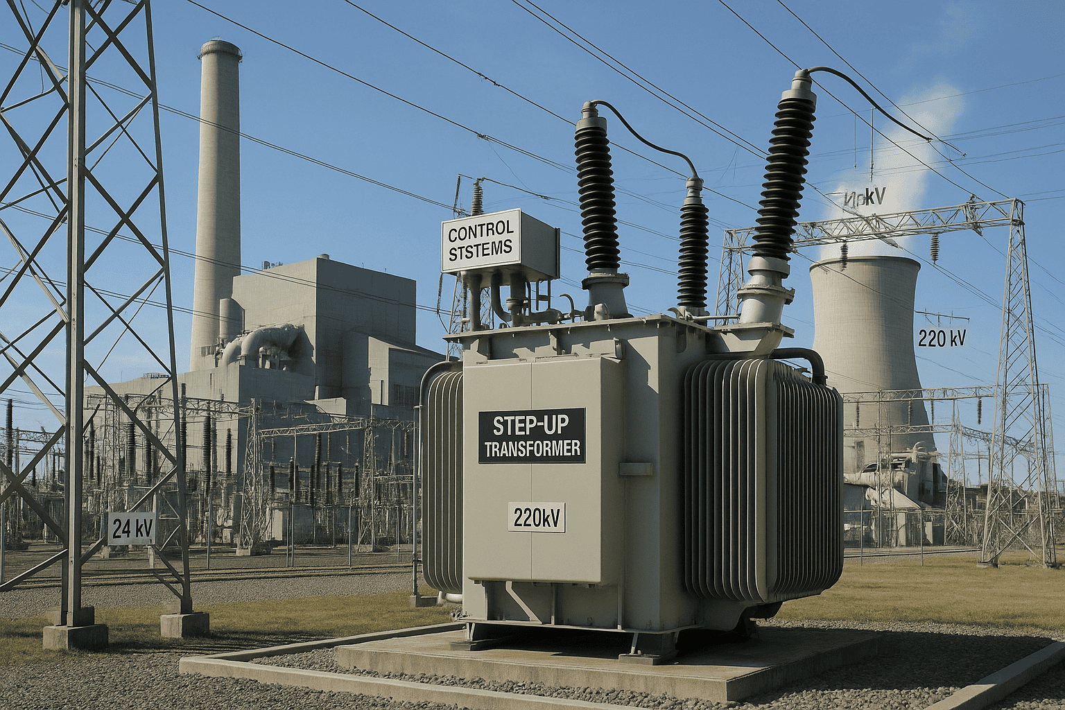
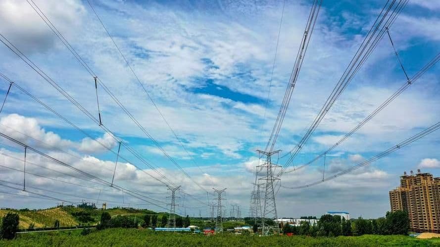
Generator transformers—often referred to as step-up transformers—play a pivotal role at the interface between power generation and transmission systems. These high-capacity transformers are essential in converting electricity generated at medium voltage levels (11–25 kV) to high transmission voltages (up to 400 kV or more), making long-distance power delivery efficient and technically feasible. Without generator transformers, massive amounts of power produced in power plants could never travel efficiently through transmission grids to reach end users.
A generator transformer is a type of power transformer installed at power generation facilities to step up the voltage from the generator output (typically 11–25 kV) to high transmission levels (typically 132 kV, 220 kV, or 400 kV). It is used between the generator terminals and the grid switchyard to enable efficient high-voltage power transmission.
Generator transformers are mission-critical assets in thermal, hydro, nuclear, and renewable power stations.
A generator transformer is used to step up voltage from generator output to transmission levels.True
Generator transformers connect the power plant’s medium-voltage generator output to the high-voltage grid infrastructure.
Generator transformers are used to directly supply low-voltage appliances from the generator.False
Generator transformers step up voltage for transmission, not down for consumption—they are not used for household or low-voltage distribution.
1. Typical Electrical Parameters
| Specification | Typical Range |
|---|---|
| Generator output voltage | 11 kV – 25 kV |
| Step-up transformer output | 110 kV – 765 kV |
| Power rating | 50 MVA – 1200+ MVA |
| Frequency | 50 Hz or 60 Hz (based on region) |
Generator transformers are among the highest-rated and most robust transformers in the grid.
2. Where Are Generator Transformers Installed?
| Power Source | Installation Site | Purpose |
|---|---|---|
| Thermal Power Plant | Between generator and GIS/switchyard | Transfers power to high-voltage transmission |
| Hydroelectric Plant | Inside or near turbine house | Steps up voltage to evacuate generated power |
| Nuclear Power Station | Close to reactor generator | Critical for secure grid connection |
| Wind Farm Collection Yard | After multiple turbines feed into MV bus | Boosts voltage before grid interconnect |
| Solar Power Plant | After inverter or centralized transformer | Raises voltage from \~690 V to 33–132 kV |
Placement depends on plant design, cooling method, and safety protocols.
3. Key Design Features of Generator Transformers
| Feature | Function and Benefit |
|---|---|
| On-load tap changers (OLTC) | Fine voltage control during grid fluctuations |
| Double-winding or three-winding design | May include auxiliary station service winding |
| Robust insulation | Handles generator surge and transient voltages |
| High short-circuit withstand | Withstands generator faults and switchyard events |
| Cooling systems (OFAF/ODAF) | Supports large continuous thermal load |
Generator transformers are built for thermal stability, overload resilience, and grid compliance.
4. Why Generator Transformers Are Critical
| Reason | Explanation |
|---|---|
| Voltage adaptation | Matches generator voltage to grid requirements |
| System reliability | Filters transients, isolates plant faults |
| Load dispatch capability | Enables bulk power transfer to remote regions |
| Grid code compliance | Ensures reactive power, tap range, and grounding standards |
They serve as the electrical gatekeeper between the power station and the grid.
5. Comparison: Generator Transformer vs. Power Transformer
| Aspect | Generator Transformer | General Power Transformer |
|---|---|---|
| Voltage input | 11–25 kV (generator) | 33–400 kV (transmission/distribution) |
| Voltage output | 110–765 kV | 33–132 kV, or down to 11 kV |
| Installation | Inside or near generation plant | Substations, grid nodes |
| Usage cycle | Continuous, high-load duty | Varies; may serve step-down or interconnection |
| Cooling system | Always advanced (ODAF/OFAF) | May be simpler (ONAN, ONAF, OFAF) |
Generator transformers are more specialized and customized than general grid transformers.
Summary Table: Generator Transformer Overview
| Parameter | Description |
|---|---|
| Function | Steps up generator voltage for transmission |
| Typical input/output | 11–25 kV → 132–400+ kV |
| Installed at | Power plants (thermal, hydro, solar, wind) |
| Capacity | 50 MVA – 1200+ MVA |
| Cooling method | OFAF, ODAF, OFWF |
| Key features | OLTC, surge protection, high dielectric |
| Critical role | Enables grid integration and long-distance power transfer |
What Is a Power Transformer and What Is Its Role in the Grid?
The modern electrical grid is a marvel of interconnected systems that must operate efficiently, reliably, and safely. At the heart of this complex infrastructure are power transformers—the unsung heroes that make it possible to transmit electricity over long distances, balance loads, and regulate voltage levels. Without power transformers, the high-voltage transmission and distribution of electricity would be inefficient, unstable, and dangerous.
A power transformer is a high-capacity electrical device used to change voltage levels between different parts of the power grid—typically from generation-level voltages to transmission or distribution voltages. Its primary role is to enable efficient long-distance transmission by stepping up voltage to reduce losses, or stepping down voltage for safe delivery to substations, industrial zones, or other infrastructure.
Power transformers are essential in transmission and sub-transmission networks, acting as critical voltage control nodes.
Power transformers are essential for voltage conversion in the transmission network of the power grid.True
They step up voltage for efficient power transmission and step down voltage for safe distribution to utilities and consumers.
Power transformers directly power residential homes at 220 volts.False
Power transformers operate at high voltages and supply substations; homes are served by smaller distribution transformers.
1. What Is a Power Transformer?
| Characteristic | Details |
|---|---|
| Voltage rating | Typically 66 kV – 765 kV |
| Power rating | 5 MVA to 1500+ MVA |
| Core design | Core-type or shell-type with high-grade laminations |
| Function | Voltage transformation without changing frequency |
| Cooling methods | OFAF, ODAF, ONAN, ONAF |
| Installation environment | Substations, transmission switchyards, power plants |
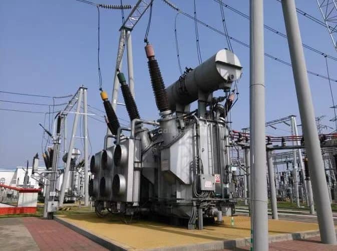
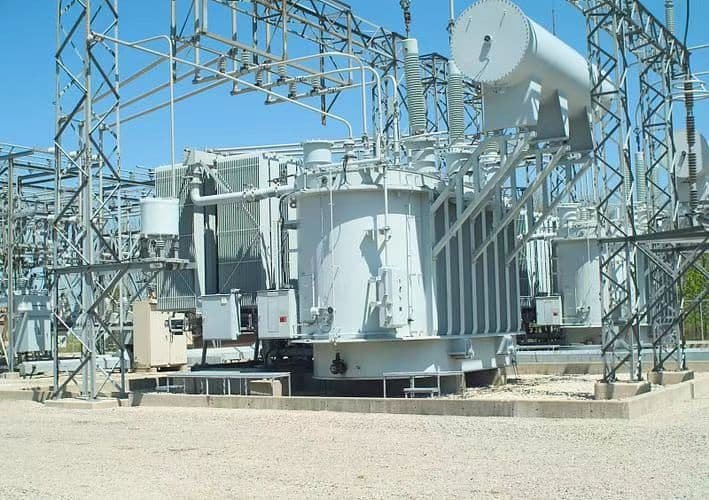
Power transformers are stationary, oil-immersed, high-voltage devices that require rigorous design and testing.
2. Role in the Power Grid
| Grid Segment | Transformer Function |
|---|---|
| Generation Plant | Steps up voltage from generator (11–25 kV) to transmission level (132–400 kV) |
| Transmission Substation | Interconnects transmission networks and regions |
| Receiving Substation | Steps down voltage (e.g., 400 kV → 132 kV or 220 kV) for sub-transmission |
| Industrial Substation | Further steps down voltage (e.g., 132 kV → 33 kV or 11 kV) for internal use |
Power transformers are used where power must be moved at scale, safely and efficiently.
3. Technical Function and Benefits
| Function | Grid Benefit |
|---|---|
| Voltage step-up/down | Matches transmission and distribution requirements |
| Impedance balancing | Reduces circulating currents and stabilizes load flow |
| Fault isolation (with protection systems) | Limits fault spread across networks |
| Load sharing and parallel operation | Enhances redundancy and capacity management |
| Tap changing | Enables voltage regulation under varying load conditions |
Power transformers improve grid flexibility, safety, and power quality.
4. Comparison: Power vs. Distribution Transformer
| Aspect | Power Transformer | Distribution Transformer |
|---|---|---|
| Voltage range | High voltage (66–765 kV) | Low to medium voltage (11 kV to 400 V) |
| Application | Generation and transmission substations | End-user voltage adaptation |
| Capacity | Typically 5–1500 MVA | Typically 25 kVA to 2.5 MVA |
| Load profile | Operates near full load constantly | Variable load, partial capacity often used |
| Installation | Outdoor, substation-grade | Pole-mounted, pad-mounted, or indoor |
Power transformers are larger, more robust, and high-voltage-rated for grid-level use.
5. Typical Power Transformer Ratings by Voltage Level
| Voltage Level | Typical Transformer Size (MVA) | Application |
|---|---|---|
| 66 kV | 5–40 MVA | Local industrial or urban substation |
| 110 kV / 132 kV | 40–160 MVA | Regional transmission |
| 220 kV | 160–315 MVA | Inter-regional transmission |
| 400 kV / 500 kV | 315–800 MVA | Bulk power transfer |
| 765 kV | 1000–1500+ MVA | National grid backbones |
Higher voltages allow greater efficiency and lower line losses in long-distance transmission.
Summary Table: Power Transformer Overview
| Parameter | Description |
|---|---|
| Purpose | Voltage transformation for transmission systems |
| Voltage range | 66 kV – 765 kV |
| Power rating | 5 – 1500+ MVA |
| Grid location | Generation, transmission, and receiving substations |
| Design features | OLTCs, cooling radiators, high dielectric strength |
| Cooling system | ONAN, ONAF, OFAF, ODAF |
| Construction | Oil-immersed, sealed tank, bushings, surge protection |
How Do Power Transformers’ Voltage Levels and Design Parameters Differ?
Power transformers are not all built alike. Their design—particularly voltage rating, insulation system, core geometry, and cooling configuration—varies significantly based on where they are used in the grid. These differences are driven by application: whether the transformer is stepping up voltage at a generation station, interconnecting grids, or stepping down at a regional substation. As voltage levels rise, so do the engineering challenges and physical requirements, including creepage distance, insulation strength, cooling intensity, and size.
Power transformers differ in voltage levels and design parameters according to their role in the grid. Transformers rated from 66 kV to 765 kV require increasingly robust insulation, larger cores, more complex winding arrangements, enhanced cooling systems, and greater mechanical strength. These parameters directly influence their physical size, cost, and performance in the transmission network.
Design precision and voltage capability are key to safe, efficient grid operation.
Power transformers with higher voltage ratings require more insulation, larger cores, and advanced cooling systems.True
As voltage increases, electrical stress rises, necessitating greater dielectric strength, thermal management, and structural reinforcement.
All power transformers share the same design regardless of voltage class.False
Transformer design changes significantly with voltage class to meet insulation, cooling, and performance requirements.
1. Voltage Classification and Design Implications
| Voltage Class | Range | Grid Role |
|---|---|---|
| Medium Voltage (MV) | >1 kV – 35 kV | Primary distribution transformers |
| High Voltage (HV) | >35 kV – 230 kV | Transmission substations, regional grids |
| Extra-High Voltage (EHV) | >230 kV – 500 kV | Bulk power transmission |
| Ultra-High Voltage (UHV) | >500 kV – 1200 kV | National backbone, long-distance transfer |
Higher voltage classes demand sophisticated insulation, greater clearances, and stricter testing protocols.
2. Insulation System Design
| Voltage Rating | Insulation Medium | Insulation Design Features |
|---|---|---|
| 66–132 kV | Oil-paper (cellulose) | Simple radial clearances, basic pressboard support |
| 220–400 kV | Multi-layer oil-paper, extended creepage | Graded insulation, capacitive bushings, foil shields |
| 500–765 kV | Advanced oil-paper, resin, SF₆ shielding | Gas-filled barriers, large axial clearances, disc windings |
Higher voltages increase dielectric stress, requiring graded insulation systems and capacitive field control.
3. Core and Winding Configuration
| Voltage Class | Core Type | Winding Construction |
|---|---|---|
| <132 kV | Core-type, two-limb | Layer windings, low turn voltage |
| 220–400 kV | Three-limb or shell-type | Helical or disc windings, high axial support |
| 500–765 kV | Three-limb, stacked core | Interleaved discs, interleaving for stress balance |
Winding design ensures mechanical rigidity and voltage uniformity under short-circuit conditions.
4. Cooling and Thermal Management
| Rating | Cooling System Used | Why It’s Needed |
|---|---|---|
| ≤66 kV | ONAN (Oil Natural Air Natural) | Natural convection adequate for low losses |
| 132–220 kV | ONAF (Oil Natural Air Forced), OFAF | Requires fans or pumps to remove heat |
| 400–765 kV | OFAF, ODAF, OFWF | Advanced cooling with directed oil and forced air/water |
Heat from copper losses and core flux must be dissipated to avoid insulation failure.
5. Bushing and Terminal Design
| Voltage Rating | Bushing Type | Design Challenge |
|---|---|---|
| ≤132 kV | Porcelain or epoxy resin | Manage surface discharge |
| 220–400 kV | Condenser-type, oil-filled bushings | Manage internal capacitive stress |
| >500 kV | SF₆ or hybrid gas-insulated bushings | Prevent flashover, external surge isolation |
Bushings are high-voltage portals—their design must withstand environmental and transient stress.
6. Size, Weight, and Logistics
| Voltage Level | Typical Mass | Transportation Requirements |
|---|---|---|
| 66–132 kV | 10–50 tons | Trailer-based transport |
| 220–400 kV | 80–180 tons | Heavy-lift, crane, modular transport |
| 500–765 kV | 200–400+ tons | Custom shipping, rail or barge logistics |
Large transformers must be factory-tested, disassembled, and reassembled on site, especially at EHV levels.
7. Testing Standards by Voltage Class
| Voltage Range | Tests Required | Standard Bodies |
|---|---|---|
| All classes | Ratio, insulation resistance, short-circuit withstand | IEC 60076, IEEE C57 |
| >132 kV | Lightning impulse, switching impulse, heat run test | Type tested at factory |
| >400 kV | Full-wave lightning impulse with front-of-wave test | Often custom per project |
Testing ensures the transformer can withstand grid faults, voltage surges, and thermal stress.
Summary Table: Voltage Level vs. Design Parameters
| Voltage Class | Core/Winding Complexity | Insulation Type | Cooling Method | Bushing Type | Weight Range |
|---|---|---|---|---|---|
| 66–132 kV | Moderate | Oil-paper basic | ONAN/ONAF | Porcelain | 10–50 tons |
| 220–400 kV | High | Layered oil-paper, graded | OFAF/ODAF | Condenser-type | 80–200 tons |
| 500–765 kV | Very high | Gas barrier, advanced foils | OFWF, ODAF | SF₆, GIS bushings | 200–400+ tons |
What Are the Key Differences in Cooling and Loading Profiles of Power Transformers?
Power transformers are engineered not only to handle specific voltages and MVA ratings but also to manage thermal stress under varying electrical loads. That’s why transformer cooling systems—ONAN, ONAF, OFAF, ODAF, and OFWF—are designed to match the transformer's loading profile. The interplay between cooling method and loading behavior affects operational safety, lifespan, efficiency, and planning for overload conditions. Choosing the wrong combination can lead to overheating, accelerated insulation aging, or even failure.
Cooling and loading profiles differ based on transformer cooling method: ONAN systems rely solely on natural oil and air convection and support only up to 100% base loading, while forced systems like ONAF, OFAF, and ODAF increase the transformer’s capacity by actively removing heat. As cooling improves, transformers can carry higher loads—temporarily or continuously—without violating temperature limits.
This relationship defines how transformers perform under real-world grid demand conditions.
Transformer cooling method directly impacts its permissible loading capacity.True
Cooling systems such as ONAF or OFAF allow for higher continuous or emergency loading due to more effective heat dissipation.
Cooling systems do not influence transformer loading capacity.False
Thermal limitations define how much load a transformer can handle safely; cooling method is key to controlling temperature rise.
1. Transformer Cooling Methods Explained
| Cooling Type | Full Form | Mechanism |
|---|---|---|
| ONAN | Oil Natural Air Natural | Natural oil circulation and ambient air convection |
| ONAF | Oil Natural Air Forced | Natural oil flow, enhanced by air fans |
| OFAF | Oil Forced Air Forced | Oil pumped and air blown through radiators |
| ODAF | Oil Directed Air Forced | Directed oil jets through windings, with forced air cooling |
| OFWF | Oil Forced Water Forced | Oil cooled by water heat exchangers (often in compact substations) |
As cooling intensity increases, transformer heat dissipation and loading capacity increase proportionally.
2. Loading Profile by Cooling Class
| Cooling Class | Base Load Capacity | Extended Loading Capacity | Usage Example |
|---|---|---|---|
| ONAN | 100% (rated MVA) | No overload | Small/medium distribution transformers |
| ONAF Stage 1 | 100% | \~133% of ONAN rating | Substations, industrial zones |
| ONAF Stage 2 | — | Up to 150% of ONAN rating | Emergency overload handling |
| OFAF | 100% | Up to 160–175% of ONAN rating | High-demand urban substations |
| ODAF | 100% | >180% with directed oil flow | EHV/GIS step-up transformers |
Fans and pumps are staged and temperature-activated, enabling dynamic cooling capacity based on load.
3. Thermal Class and Load Management
| Thermal Class | Hot-Spot Rise Limit | Implication for Loading |
|---|---|---|
| Class A (Oil-paper) | 65 °C | Moderate overloads tolerated for short durations |
| Class B or F | 80–100 °C | Higher overloads allowed under control |
| Synthetic fluids or esters | 120+ °C (in some cases) | Extended emergency rating in special applications |
Hot-spot temperatures must be monitored closely during overload conditions to avoid accelerated aging.
4. Cooling vs. Load Duration Curve
| Load Duration | Cooling Method Required | Reason |
|---|---|---|
| 0–100% Rated Load | ONAN sufficient | Base operation |
| 100–125% for hours | ONAF Stage 1 | Short peak handling without thermal fatigue |
| 125–150% for emergency | ONAF Stage 2 or OFAF | Requires active cooling to control winding heat |
| >150% for minutes | ODAF or OFWF + temperature alarms | Short-term grid fault ride-through |
Design must consider load cycles, ambient temperature, and cooling activation thresholds.
5. Key Design Differences Based on Cooling
| Cooling Type | Core Design | Cooling Accessories | Monitoring Systems |
|---|---|---|---|
| ONAN | Basic tank and fins | Radiators only | WTI, OTI |
| ONAF | Same as ONAN + fans | Radiators with axial or centrifugal fans | Fan controller, bimetal relays |
| OFAF | Heavier-duty core | Oil pumps + radiator fans | Pump starters, differential pressure sensors |
| ODAF | Winding ducts + baffles | Oil injectors + enhanced air system | SCADA, remote telemetry |
| OFWF | Compact core | Oil-water heat exchanger + fluid loops | Temperature alarms, water quality sensor |
Higher cooling grades require more monitoring, control logic, and fault protection mechanisms.
Summary Table: Cooling & Loading Profile Comparison
| Cooling Type | Max Load Capacity | Best For | Cooling Complexity | Maintenance Level |
|---|---|---|---|---|
| ONAN | 100% | Basic, steady loads | Low | Minimal |
| ONAF | 133–150% | Urban substations, industry | Moderate (fans) | Moderate |
| OFAF | 160–175% | Transmission-level substations | High (fans + pumps) | High |
| ODAF | >180% | GSU, EHV transformers | Very high | Very high |
| OFWF | 180%+ (compact setups) | Nuclear, marine, or dense cities | Extreme (fluid loops) | Specialized |
Why Do Generator Transformers Have Special Short-Circuit Ratings?
In the power generation process, generator transformers are the first interface between the high-current generator output and the high-voltage transmission network. Because of this critical position, they are exposed to the highest levels of electrical and mechanical stress during abnormal events such as short circuits or generator faults. If not specifically designed for these events, a generator transformer can suffer catastrophic internal failure. That’s why special short-circuit withstand ratings are a fundamental part of generator transformer engineering.
Generator transformers require special short-circuit ratings because they are directly connected to the generator’s low-voltage, high-current output, which can result in extremely high fault currents. These transformers must withstand both thermal and mechanical stresses from such faults without deformation, displacement, or insulation failure. This requires robust winding support, reinforced insulation, and compliance with IEC 60076-5 or IEEE C57.12.00 short-circuit testing standards.
These transformers are engineered to survive the worst-case scenarios in the shortest time.
Generator transformers must be specially rated to withstand high short-circuit currents from connected generators.True
Generators can deliver very high fault currents instantly, and generator transformers must be mechanically and thermally reinforced to survive such events.
Generator transformers do not experience significant short-circuit stress and can use standard designs.False
Generator transformers face some of the highest fault current levels in the grid and require enhanced short-circuit withstand capability.
1. Why Generator Transformers Face Higher Fault Currents
| Source | Impact on Transformer |
|---|---|
| Generator output impedance is low | Allows very high fault current (10–25 times nominal) |
| Fault occurs near transformer terminals | Peak asymmetrical currents exceed 200 kA in milliseconds |
| Close proximity to source | No network impedance to limit fault current |
Generator-side faults produce extremely high mechanical forces within windings, especially at the LV terminals.
2. Short-Circuit Rating Requirements
| Test Condition | Required Capability |
|---|---|
| Thermal withstand (1–3 seconds) | Windings must survive I²t heating effect |
| Mechanical withstand | Windings must resist dynamic forces from magnetic fields |
| Axial and radial stress | Core and clamping structure must not deform |
| Dielectric integrity | No breakdown between turns or layers |
These ratings are defined in IEC 60076-5 or IEEE C57.12.00, and must be verified by type test or design simulation.
3. Mechanical Reinforcements in Design
| Design Element | Short-Circuit Protection Role |
|---|---|
| Axial clamping rings | Prevent coil movement during magnetic shock |
| Epoxy-glass spacers | Distribute force uniformly between winding layers |
| Rigid winding supports | Prevent buckling or bulging during fault surge |
| Multi-start disc windings | Improve mechanical integrity and current sharing |
| Conductor bracing | Reduces movement under Lorentz force during asymmetry |
Generator transformers must withstand peak dynamic forces over 100,000 kgf per winding turn.
4. Thermal Considerations During Short Circuit
| Condition | Temperature Rise and Effect |
|---|---|
| 2s short-circuit event | Windings may heat by over 250 °C |
| Oil flash point risk | Requires flame-retardant insulation and pressure relief |
| Conductor annealing risk | Can cause loss of copper mechanical strength |
Thermal stress is not just heat—it’s heat combined with mechanical distortion.
5. Protection Coordination with Switchgear
| System Component | Coordination with Transformer |
|---|---|
| Generator circuit breakers | Must clear fault before winding damage |
| Differential relays | Detect transformer faults within milliseconds |
| Overcurrent protection | Limits duration of short-circuit exposure |
Generator transformers rely on very fast protective relaying to minimize short-circuit stress duration.
6. Typical Short-Circuit Ratings by Transformer Size
| Transformer Rating (MVA) | Typical Short-Circuit Rating (kA, 1s) | Application |
|---|---|---|
| 50 MVA | 31.5 kA | Mid-size hydro, gas plants |
| 100 MVA | 40–50 kA | Thermal generation |
| 300 MVA | 63–80 kA | Combined cycle or large hydro |
| 500+ MVA | 100–160 kA | Nuclear, supercritical plants |
Larger generator transformers often require custom fault withstand engineering.
Summary Table: Generator Transformer Short-Circuit Design Focus
| Aspect | Design Consideration |
|---|---|
| Electrical proximity | Direct generator connection (zero impedance path) |
| Fault current level | 10–25 times nominal current |
| Thermal withstand | 1–3 seconds without insulation breakdown |
| Mechanical strength | Windings must not move or deform |
| Regulatory standard | IEC 60076-5 / IEEE C57.12.00 |
| Testing method | Simulated via FEM or real short-circuit lab test |
How Does Their Placement in the Power System Distinguish Generator Transformers?
Among all transformer types in the power network, generator transformers have the most distinct and strategic placement. Positioned immediately after the electricity generation unit, they serve as the first critical interface between the power plant and the high-voltage transmission system. This location exposes them to unique electrical conditions, including high fault current potentials and large thermal loads, distinguishing them from other transformers used later in the grid for stepping down or distributing power.
Generator transformers are uniquely placed between the power plant's generator output and the transmission grid switchyard. They step up the generator voltage (typically 11–25 kV) to high transmission voltages (110–765 kV), enabling efficient long-distance power transfer. Their position exposes them to direct generator currents, transient stresses, and grid dynamics, which requires special design for thermal, mechanical, and short-circuit performance.
This placement is what sets generator transformers apart in function, responsibility, and design.
Generator transformers are located between the generator and the transmission system to step up voltage for efficient grid integration.True
Their placement directly after generation and before the grid allows voltage elevation and fault isolation, optimizing energy delivery.
Generator transformers are installed at the end of the distribution line to reduce voltage for residential users.False
That role belongs to distribution transformers; generator transformers operate at the generation-transmission interface.
1. Power System Structure and Transformer Placement
| Power System Level | Transformer Type Used | Voltage Role |
|---|---|---|
| Generation Station | Generator Transformer | Step-up (e.g., 15 kV → 400 kV) |
| Transmission Substation | Power Transformer | Step-down/interconnect (e.g., 400 kV → 132 kV) |
| Distribution Substation | Distribution Transformer | Step-down (e.g., 33 kV → 11 kV) |
| End-User Supply | Pole-Mounted Transformer | Final step-down (e.g., 11 kV → 400 V) |
Generator transformers are the entry point into the transmission grid.
2. Electrical Environment at Generator Transformer Location
| Characteristic | Why It Matters |
|---|---|
| Low generator impedance | Allows very high fault current during events |
| High power output | Requires large capacity (50–1500+ MVA) |
| Transient-prone zone | Generator switching, synchronization, and turbine trips create surges |
| Frequency stability point | Closest to the generation frequency control |
Their placement demands enhanced surge protection, thermal endurance, and rigid mechanical design.
3. Functional Differentiation Based on Location
| Transformer Type | Location | Function |
|---|---|---|
| Generator Transformer | Right after generator terminals | Step-up voltage for transmission |
| Transmission Transformer | Between grid voltage levels | Interconnect zones or regions |
| Distribution Transformer | At substation or near consumers | Step-down for final use |
Generator transformers initiate the transmission process, others manage or finalize delivery.
4. Physical and Operational Characteristics Driven by Placement
| Design Feature | Reason Based on Placement |
|---|---|
| Short-circuit withstand | Generator faults cause high current surges |
| Advanced cooling (ODAF/OFAF) | Generator output is continuous and high-power |
| OLTC often not present | Fixed ratio preferred for grid stability |
| Transformer housed near turbine | Must fit into power plant layout |
Generator transformers are customized to the dynamics of power plants, unlike generic grid transformers.
5. Why Placement Affects Testing and Monitoring
| Design Implication | Operational Priority |
|---|---|
| Closer to generation | Requires integration with generator protection relays |
| Subject to islanding and syncing | Must support stable grid re-entry |
| First fault point | Equipped with surge arresters and Buchholz relay |
| Vital for energy evacuation | Must be online continuously; high reliability |
Their proximity to generation means any transformer failure equals full plant shutdown.
Summary Table: Generator Transformer Placement and Role
| Attribute | Generator Transformer |
|---|---|
| Location | Between generator terminals and HV switchyard |
| Primary Function | Step-up generator voltage for grid transmission |
| Input Voltage | 11–25 kV |
| Output Voltage | 110–765 kV |
| Typical Load | Continuous, near 100% loading |
| Key Risks | Fault currents, thermal overload, transients |
| Design Considerations | Short-circuit strength, robust insulation, cooling |
Conclusion
Generator transformers (GSUs) are directly connected to power generators and typically operate at low voltage (on the generator side) and high current. They step up the voltage to transmission levels. Power transformers, on the other hand, are used within the transmission and distribution network to transfer energy between voltage levels and handle load variations. Generator transformers require higher short-circuit strength and continuous operation under full load, while power transformers are optimized for efficient voltage regulation and long-distance transmission support.
FAQ
Q1: What is the main difference between a generator transformer and a power transformer?
A1: The main difference lies in their function and application:
A generator transformer (often called a GSU – Generator Step-Up Transformer) connects directly to a generator and steps up voltage from generation level (e.g., 11–25kV) to transmission level (e.g., 132–400kV).
A power transformer is used in transmission networks to step up or step down voltage between transmission and sub-transmission or distribution systems.
Q2: How do their voltage levels differ?
A2: Generator transformers handle low to high voltage conversion, typically 11–25kV up to 132–400kV.
Power transformers operate primarily at high or ultra-high voltages, such as 220kV, 400kV, 765kV, used for bulk transmission between substations.
Q3: What are their differences in loading and operation?
A3: Generator transformers are designed to run close to full load continuously, matching the generator output.
Power transformers may experience variable loading based on transmission demands and grid balancing.
Q4: Are their winding configurations different?
A4: Yes.
Generator transformers usually have a delta connection on the primary (generator side) and star on the secondary (grid side) to provide a neutral point and prevent circulating currents.
Power transformers may have star-star, delta-delta, or other vector group configurations depending on network design and grounding requirements.
Q5: Where are they installed in the power system?
A5: Generator transformers are located between the generator and the grid, inside power plants.
Power transformers are found at transmission substations, interconnecting various parts of the electrical grid.
References
"Generator Transformer vs Power Transformer Explained" – https://www.transformertech.com/generator-vs-power-transformer
"Understanding Generator Step-Up Transformers" – https://www.electrical4u.com/generator-transformer-function
"Key Differences Between Generator and Power Transformers" – https://www.powermag.com/generator-transformer-vs-power-transformer
"Energy Central: Transformer Roles in Power Networks" – https://www.energycentral.com/c/ee/transformer-differences
"Smart Grid News: Generator Transformer Use Cases" – https://www.smartgridnews.com/generator-transformer-guide
"ScienceDirect: Application-Based Transformer Classification" – https://www.sciencedirect.com/generator-power-transformer-study
"ResearchGate: Analysis of Generator and Power Transformer Functions" – https://www.researchgate.net/generator-vs-power-transformer
"PowerGrid: Generator Step-Up Transformer Overview" – https://www.powergrid.com/gsu-vs-power-transformers