Power transformers are critical in high-voltage transmission and large-scale power systems, but like any technology, they come with limitations. Understanding these disadvantages is key to system design, maintenance planning, and selecting the right equipment for specific environments or applications.
What Are the Size and Weight Challenges of Power Transformers?
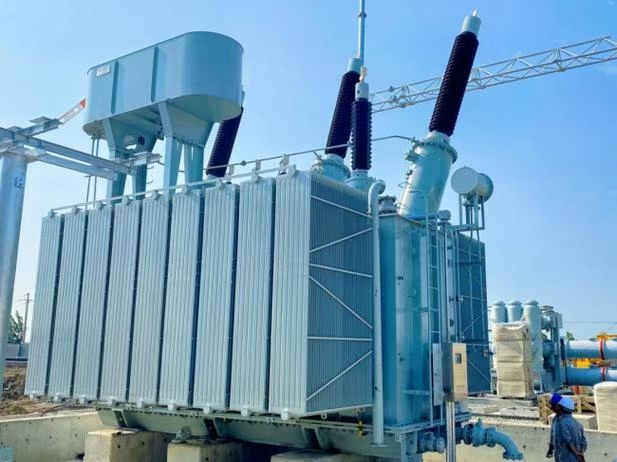
Power transformers are the giants of electrical infrastructure—massive machines engineered to move megawatts of power through high-voltage networks. But this performance comes at a cost: sheer physical scale. These transformers often weigh dozens to hundreds of tons, span several meters in height and length, and require custom transportation, structural support, and foundation work. Their size and weight present significant challenges across the entire project lifecycle, from manufacturing to logistics, installation, and maintenance.
The size and weight challenges of power transformers arise from the need to handle high voltages, high currents, and extreme thermal and magnetic loads. This requires large volumes of copper or aluminum windings, heavy laminated cores, robust insulation, and massive oil-filled tanks or cooling systems. These components result in transformers that can exceed 300 tons, span 8–12 meters in length, and require special handling during transport, craning, and commissioning.
Managing these factors demands precise planning, specialized infrastructure, and experienced technical execution.
Power transformers present significant size and weight challenges due to the materials and structural demands of handling high voltages and currents.True
Their magnetic cores, windings, insulation systems, and cooling tanks are built to withstand extreme electrical and thermal stress, resulting in massive dimensions and weight.
Power transformers are lightweight devices that can be installed with standard commercial equipment.False
Even medium-sized power transformers can weigh over 50 tons and require heavy lifting cranes, reinforced foundations, and route clearance for delivery.
Why Power Transformers Are So Large and Heavy
| Component | Reason for Bulk |
|---|---|
| Magnetic Core | CRGO or amorphous steel laminated sheets up to several tons to minimize losses |
| Windings (HV/LV) | Thick copper/aluminum conductors to handle megampere currents |
| Insulation Layers | Paper, oil, and solid insulation to withstand up to 765 kV |
| Cooling Systems | Oil tanks, radiators, fans, or pumps for continuous heat dissipation |
| Tank and Frame | Steel structure with pressure and fault withstand capacity |
| Bushings and Tap Changers | HV-rated porcelain or resin components with mechanical drive systems |
Each component adds weight, and the whole must resist electrical, thermal, and mechanical stress simultaneously.
Typical Size and Weight by Transformer Rating
| Transformer Rating | Typical Dimensions (L×W×H) | Total Weight (including oil) | Application |
|---|---|---|---|
| 50 MVA / 132 kV | 4.5 m × 2.5 m × 3.5 m | \~70–90 tons | Regional substations |
| 100 MVA / 220 kV | 6.0 m × 3.0 m × 4.0 m | \~120–160 tons | Transmission hubs |
| 315 MVA / 400 kV | 7.5 m × 3.5 m × 5.5 m | \~280–350 tons | National grid interconnection |
| 500 MVA / 765 kV | 10–12 m × 4.5 m × 6 m | 400+ tons | Ultra High Voltage (UHV) corridors |
These transformers are too large for standard road or rail systems and often require modular or barge transport.
Transport and Installation Challenges
| Phase | Challenge |
|---|---|
| Manufacturing | Special bays, gantry cranes, and heavy-duty floor loading |
| Transport Logistics | Oversize load permits, custom trailers, reinforced roads |
| Craning & Rigging | Mobile cranes or gantries with 250–500 ton lifting capacity |
| Foundation Preparation | Deep pilings, vibration damping, and oil containment basins |
| Assembly On-Site | Core + winding stack often shipped separately and assembled onsite |
These steps increase installation time and cost, and demand tight project coordination.
Case Study: 250 MVA 220/132 kV Power Transformer
- Manufactured Weight (core + tank): 135 tons
- Oil Volume Required: 28,000 liters
- Shipping Configuration: Core and windings in one crate, radiators and bushings separate
- Transport Route: Required 7-axle hydraulic trailer, 5 route clearances, 2 bridge reinforcements
- Installation Timeframe: 2 weeks (foundation + assembly + oil filling + testing)
Precise handling protocols and expert teams are essential for safe delivery and commissioning.
Design Choices to Manage Size and Weight
| Design Element | Effect on Size/Weight |
|---|---|
| Core Type (Shell vs Core) | Shell cores are more compact for same rating |
| Aluminum vs Copper Windings | Aluminum is lighter but requires more volume |
| Compact Tank Design | Optimized layout reduces footprint and crane lift requirement |
| Dry-Type Alternatives | Only feasible up to \~2.5 MVA; no oil, smaller footprint |
Material and configuration optimization can reduce logistical complexity without sacrificing performance.
Environmental and Site Impacts
- Crane Pads and Rigging Zones: Require large cleared areas
- Noise Buffer Zones: HV transformers often exceed 65 dB at 1m
- Oil Spill Containment: Mandatory for large oil-filled units
- Earthquake and Wind Load Anchoring: Required in seismic or high-wind areas
Sites must be engineered to accommodate weight, sound, and environmental safety requirements.
How Do Installation and Transportation Pose Practical Limitations?
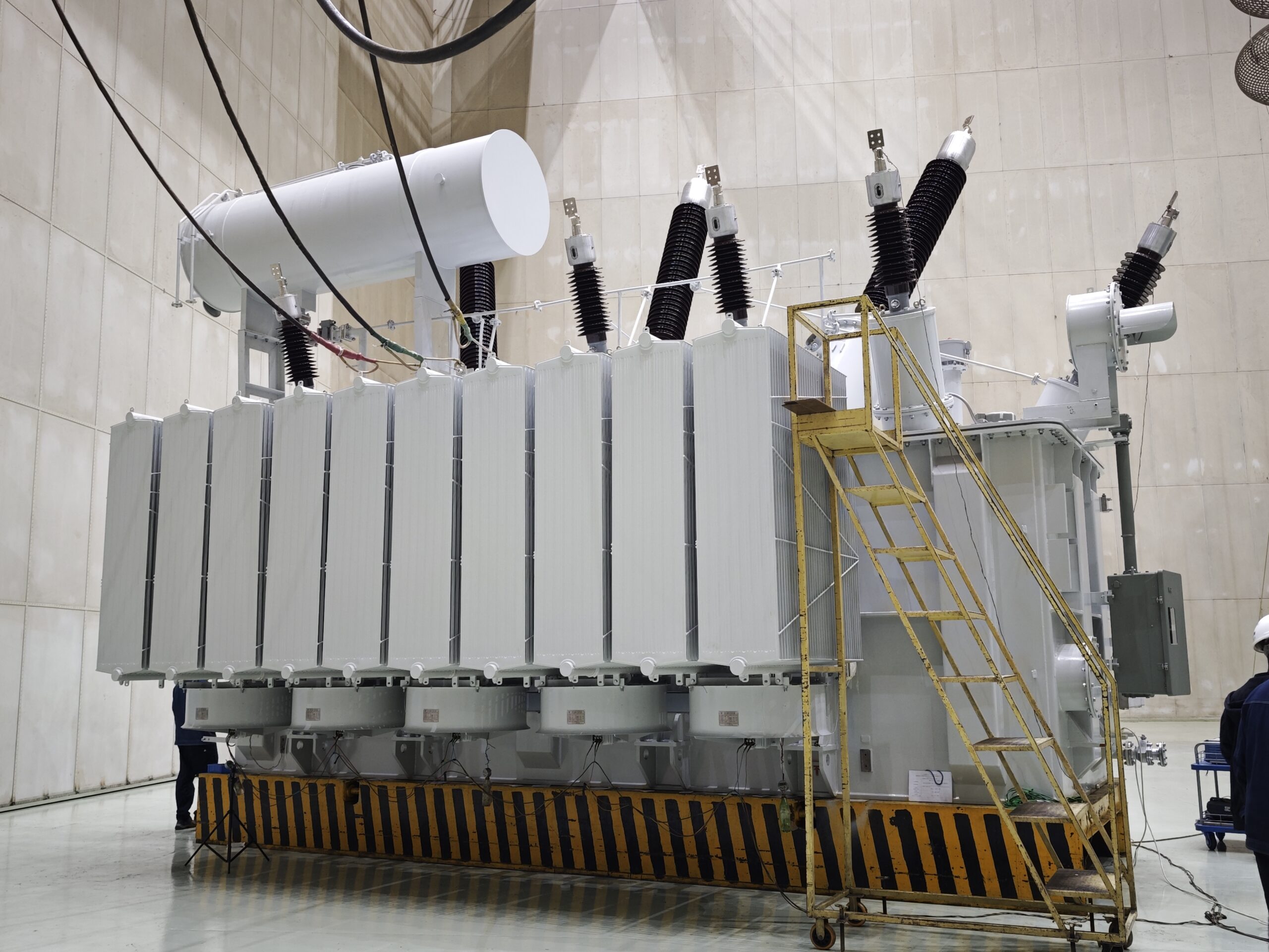
Installing a large power transformer isn’t as simple as plugging in a box—it’s a multi-stage, highly coordinated process that often takes weeks or months to execute. While transformers are engineered for efficiency and longevity, their immense weight and size create serious logistical and operational limitations. These limitations aren’t just technical—they influence where you can install, how you design access roads, what equipment you need, and even how much your substation foundation must support. Failing to account for these real-world constraints can lead to cost overruns, project delays, and safety hazards.
Installation and transportation pose practical limitations for power transformers due to their immense size, extreme weight, and sensitivity to vibration and handling. Moving a transformer to its site may require route surveys, bridge reinforcements, road modifications, special permits, and multi-axle trailers. Installation requires cranes with high lifting capacity, deep foundations, environmental compliance, and weeks of on-site assembly, oil filling, and testing. These limitations must be factored into early design, procurement, and project management.
They are not afterthoughts—they are core constraints that shape the project from the outset.
Power transformer installation and transport are complex processes that require special equipment, permits, and engineering considerations.True
Due to their size, weight, and sensitivity, power transformers must be transported using heavy-load logistics and installed with cranes and reinforced foundations.
Transformers can be installed and transported like typical industrial machines using standard equipment.False
Large power transformers far exceed standard shipping dimensions and weights, requiring specialized equipment and planning.
Transportation Challenges in the Real World
| Aspect | Limitation or Risk |
|---|---|
| Size and Weight | Typical units weigh 100–400+ tons and are over 10 meters long |
| Road Infrastructure | Many roads, bridges, or tunnels cannot support the load or clearance |
| Route Clearance | Requires detailed survey of overpasses, curves, turning radii |
| Permits and Escorts | Special transport permits, police escorts, and time-of-day limits |
| Transport Time | Multi-day or multi-week journeys depending on terrain and weather |
| Handling Sensitivity | Vibration, tilting, or impact can damage core or winding structure |
For many installations, just reaching the site is half the battle.
Typical Transport Equipment Used
| Equipment Type | Purpose |
|---|---|
| Multi-Axle Hydraulic Trailer | Distributes load over many wheels (e.g., 10–20 axles) |
| Self-Propelled Modular Transporter (SPMT) | Used in confined or unstable terrains |
| Flatbed Rail Car | Used for long-haul rail when roads are not viable |
| Barge Transport | Used for cross-river, island, or port-based delivery |
| Escort and Support Vehicles | Ensure safe navigation, traffic management |
Installation Site Challenges
| Installation Step | Key Limitation |
|---|---|
| Foundation Preparation | Requires high bearing capacity (>10 tons/m²), oil containment systems |
| Crane Lifting | Lifts up to 300+ tons; must be stabilized and leveled |
| Weather Impact | Wind, rain, or snow can delay rigging or lifting operations |
| Oil Filling and Dehydration | Must be done carefully to avoid moisture contamination |
| Assembly Time | Radiators, tap changers, bushings added on-site (1–3 weeks) |
| Testing and Commissioning | High-voltage, insulation, and functionality tests |
Installing a large power transformer is not plug-and-play—it’s an engineered event.
Real-World Example: 315 MVA 400/220 kV Power Transformer
Transport Route:
- 350 km from factory to substation
- 13 bridges reinforced
- 2-week multi-axle trailer journey with state permits
Site Installation:
- Crane capacity: 500 tons
- Foundation depth: 2.5 meters with oil bund
- Total time: 5 weeks (from arrival to energization)
Any delay in these steps can impact entire transmission schedules or grid availability.
Costs and Risks of Poor Planning
| Consequence | Impact |
|---|---|
| Delivery Delay | Project timeline extended; may affect contract milestones |
| Improper Craning | Core displacement or internal damage |
| Inadequate Foundation | Vibration, misalignment, or tank rupture |
| Regulatory Non-Compliance | Fines, rework, or environmental penalties |
| Access Road Collapse | Transport vehicle immobilized or damaged |
Failing to plan for logistics means planning to fail in performance.
Best Practices for Overcoming These Limitations
| Action | Benefit |
|---|---|
| Early Route Feasibility Study | Identifies infrastructure improvements before shipment |
| Factory-Tested Modular Shipment | Ships in parts to reduce weight/height for clearance |
| Prefabricated Foundations | Speeds up installation timeline |
| Dedicated Lift Plan and Craning Contractor | Ensures safe, precision rigging and handling |
| Site Environmental Preparation | Prevents oil spill, flashover, and vibration issues |
| Collaborative Planning with Utility, EPC, and OEM | Aligns scope, roles, and technical interfaces |
What Are the Cooling and Ventilation Requirements?
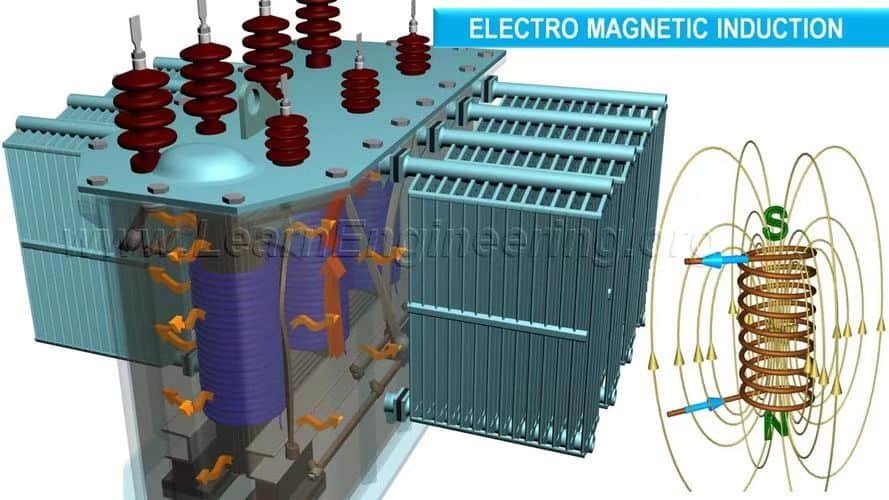
A power transformer’s ability to transfer hundreds of megawatts of energy depends not only on voltage and current—but also on temperature management. When electricity flows through the transformer windings and magnetic core, it generates heat due to core losses (hysteresis and eddy currents) and copper losses (I²R losses). Without proper cooling and ventilation, this heat can lead to insulation failure, reduced lifespan, or even catastrophic damage. That’s why cooling systems are not optional—they’re a critical part of transformer design and operation, directly impacting reliability, efficiency, and safety.
Cooling and ventilation systems in power transformers are designed to remove the heat generated by electrical losses in the core and windings, using methods such as natural air flow, oil circulation, forced-air or forced-oil cooling, and sometimes water or heat exchangers. The chosen system must maintain transformer operating temperature within safe limits (typically ≤105°C for insulation class A) and ensure stable thermal performance under all load conditions.
Proper thermal design extends service life, prevents overloads, and safeguards grid continuity.
Power transformers require dedicated cooling and ventilation systems to maintain safe operating temperatures.True
The internal losses from magnetic flux and resistive heating can cause overheating without active or passive cooling solutions.
Ventilation is not important in power transformers because the heat is minimal.False
Power transformers can lose several kilowatts as heat, and inadequate cooling leads to insulation degradation and transformer failure.
Why Cooling Is Critical in Power Transformers
| Source of Heat | Description | Impact if Uncooled |
|---|---|---|
| Core Loss (No-Load Loss) | Hysteresis and eddy currents in magnetic core | Steady heat even when unloaded |
| Copper Loss (Load Loss) | Resistance heating from load current | Scales with I² and causes hot spots |
| Ambient Heat Accumulation | Solar or nearby equipment heat | Adds to operating temperature |
| Dielectric Heating | Small but relevant in high-frequency applications | Localized thermal stress |
Even moderate-sized transformers (10–50 MVA) can generate 5–20 kW of heat under load, which must be continuously removed.
Common Cooling Methods
| Code | Full Form | Cooling Description |
|---|---|---|
| ONAN | Oil Natural Air Natural | Oil circulates by convection; air cools the tank and radiators passively |
| ONAF | Oil Natural Air Forced | Oil moves naturally, but fans force air across radiators for better heat dissipation |
| OFAF | Oil Forced Air Forced | Both oil and air are pumped; common in >100 MVA power transformers |
| OFWF | Oil Forced Water Forced | Water-cooled heat exchangers used in very high-capacity transformers or confined spaces |
| Dry Type | Air-cooled (AN/AF) | Used in indoor/low MVA settings; relies on air circulation or fans, no oil used |
Cooling class must be selected based on MVA rating, site environment, and space constraints.
Transformer Cooling System Components
| Component | Function |
|---|---|
| Radiator Panels | Surface area for oil-to-air heat exchange |
| Cooling Fans | Boost airflow for forced-air systems |
| Oil Pumps | Circulate oil in forced-oil systems |
| Temperature Sensors | Monitor hot-spot, top oil, and ambient temperatures |
| Buchholz Relay | Detects gas buildup from overheating faults |
| Conservator Tank | Maintains oil volume and thermal expansion |
| Breather with Silica Gel | Prevents moisture ingress while maintaining air flow |
| Thermal Relays | Trip transformer if temperature exceeds safe limits |
Thermal Limits and Insulation Classes
| Insulation Class | Max Operating Temperature (°C) | Typical Use |
|---|---|---|
| Class A | 105°C | Distribution/power transformers |
| Class B | 130°C | Industrial dry-type transformers |
| Class F | 155°C | Control transformers, compact units |
| Class H | 180°C | High-heat compact electronics |
Exceeding these limits can shorten insulation life dramatically. For every 10°C rise, insulation life halves.
Real-World Case Study: 250 MVA ONAN/ONAF Transformer
- Cooling Type: ONAN up to 150 MVA, ONAF up to 250 MVA
- Radiator Panels: 12 detachable banks
- Cooling Fans: 8 axial fans, temperature-controlled
- Max Oil Temp: 85°C during summer peak load
- Ambient Air: 45°C
- Heat Dissipated: \~25 kW at full load
- Oil Volume: \~30,000 liters
- Sensors: Top oil, winding RTDs, ambient, with SCADA alerts
System ensured stable operation at 99% rated capacity in peak summer without overheating or trips.
Indoor Transformers: Ventilation Requirements
| Installation Type | Ventilation Considerations |
|---|---|
| Dry-Type Transformer Room | Requires air ducting and exhaust fans to prevent hot air buildup |
| Pad-Mounted Units | Needs rear and side clearance for convective cooling |
| Underground Vaults | Must include forced air exchange and heat alarms |
| Containerized Substations | Built-in fans and louvers, possibly HVAC for temperature control |
For enclosed spaces, ventilation design must match transformer loss rating (in kW) to avoid ambient heat accumulation.
Monitoring and Automation for Cooling
| Technology | Function |
|---|---|
| Remote Temperature Monitoring (SCADA) | Enables real-time load and thermal response |
| Fan Automation | Activates cooling based on winding or oil temperature |
| Oil Flow Sensors | Alerts if oil circulation is blocked |
| Digital Twins & Thermal Models | Predict overheating and optimize fan/pump schedules |
Smart cooling improves efficiency and transformer life while reducing unnecessary energy consumption.
How Do Power Transformers Impact Environmental and Fire Safety?
Power transformers are the silent workhorses of the electric grid—but despite their passive appearance, they can pose significant environmental and fire risks if not properly designed, maintained, or protected. These large machines contain thousands of liters of insulating oil, operate under high voltages, and carry enough energy to spark fires or spills if a failure occurs. Understanding and managing these risks is not optional—it’s critical for regulatory compliance, public safety, and environmental stewardship.
Power transformers impact environmental and fire safety through their use of insulating fluids, risk of oil leaks, potential for arc-induced fires, and emissions in the event of failure. These risks are mitigated by implementing containment basins, fire suppression systems, pressure relief devices, flame-retardant fluids, and environmental monitoring. Compliance with standards like NFPA, IEC, IEEE, and local environmental regulations ensures transformers operate safely without harming people or ecosystems.
These safety measures are essential in both urban and rural installations to protect infrastructure, personnel, and the environment.
Power transformers must include safety features to prevent environmental damage and fires caused by oil leaks or electrical faults.True
Transformers operate at high voltage with combustible oil, requiring fire barriers, containment, and protective relays to ensure safe operation.
Transformer failures rarely cause environmental or fire hazards, so safety systems are optional.False
Failures can result in oil fires, explosions, and toxic emissions, making safety features legally and operationally essential.
Environmental Safety Concerns and Mitigation
| Concern | Potential Impact | Preventive Measures |
|---|---|---|
| Oil Leakage | Soil and groundwater contamination | Oil containment pits, bund walls, absorbent beds, leak detection |
| Cooling Oil Spills | Surface pollution, vegetation damage | Use of non-toxic, biodegradable oils (ester fluids) |
| Explosion or Rupture | Oil spray, thermal damage to nearby ecosystems | Pressure relief valves, gas detection relays, firewalls |
| Airborne Emissions (in fire) | Release of toxic gases (e.g., PCB in older units) | Replace PCB-filled units, install smoke filtration and ventilation |
A 100 MVA transformer may contain 20,000–40,000 liters of oil—making containment and monitoring a top environmental priority.
Fire Safety Hazards in Power Transformers
| Hazard | Cause | Mitigation Strategies |
|---|---|---|
| Internal Arcing | Insulation failure, surge, overload | Buchholz relay, surge arresters, differential protection |
| Overheating | Cooling failure, overload, poor ventilation | Thermal sensors, forced cooling, trip mechanisms |
| Oil Ignition | Leaked oil contact with hot surface or arc flash | Flame-retardant fluids, fire barriers, automatic suppression |
| Explosion Risk | Sudden pressure buildup inside the tank | Pressure relief device (PRD), nitrogen cushion, fault tripping |
Transformer fires can burn for hours and cause widespread grid outages, property damage, or injury if not contained.
Key Safety Features in Modern Power Transformers
| Component | Function |
|---|---|
| Oil Containment Pit | Prevents oil from contaminating soil or drains |
| Pressure Relief Device | Releases excess pressure in the event of fault-induced gas expansion |
| Buchholz Relay | Detects slow gas accumulation and minor arcing |
| Fire Suppression System | Automatically sprays foam or inert gas on detected fire |
| Fire Barriers | Separates transformers to prevent cascading fires |
| Temperature Sensors | Monitors winding and oil hot spots to prevent overheating |
| Leak Detection Sensors | Warns of seal or bushing failure before major leak occurs |
Fire and Environmental Protection Standards
| Standard | Scope of Safety Coverage |
|---|---|
| NFPA 850 | Recommended Fire Protection Practices for Electric Generating Plants |
| IEEE C57.12.00 | Design and testing requirements for power transformers |
| IEC 60076-11 | Safety for dry-type transformers |
| ISO 14001 | Environmental management system certification |
| EPA SPCC Rules (USA) | Spill prevention, control, and countermeasures for oil-containing units |
Meeting these standards helps utilities minimize legal risk and environmental liability.
Alternative Fluids for Enhanced Safety
| Fluid Type | Fire Point | Environmental Benefit |
|---|---|---|
| Mineral Oil | \~170°C | Widely used but flammable and not biodegradable |
| Natural Ester (e.g., FR3) | >300°C | High fire point, biodegradable, lower emissions |
| Synthetic Ester | >250°C | Flame retardant and used in confined installations |
| Silicone Fluid | \~300°C | Self-extinguishing, suitable for indoor use |
| Dry-Type (No Oil) | N/A | Eliminates oil risk but limited to <2.5 MVA units |
Flame-retardant and biodegradable fluids reduce both fire and environmental risk, especially in urban or water-sensitive locations.
Real-World Example: 220 kV Transformer Fire Safety Design
- Oil Volume: 24,000 liters
- Containment: Concrete oil pit with 110% capacity + drain valve
- Detection: Buchholz relay, top oil thermometer, winding RTDs
- Fire Control: Flameproof nitrogen system with thermal sensors
- Spacing: 10-meter firewall clearance between transformers
- Fluids Used: Natural ester with >300°C fire point
- Certification: ISO 14001 and NFPA 850 compliance
The system was tested under simulated fault to ensure automatic containment and fire suppression under 60 seconds.
What Are the Costs of Maintenance and Operation?

Power transformers are long-life assets designed to serve 25–40 years or more—but that longevity depends heavily on careful, continuous maintenance and efficient operational oversight. While upfront procurement and installation grab the spotlight in budget planning, the real cost drivers over a transformer's lifecycle are in energy losses, preventive maintenance, condition monitoring, and repairs. Failure to manage these costs effectively can lead to unplanned outages, derating, or catastrophic failure, with consequences that far exceed any savings from deferred maintenance.
The costs of maintaining and operating power transformers include energy loss costs (no-load and load losses), routine maintenance (oil testing, thermal scanning, cleaning), condition monitoring systems, labor, spare parts, and unscheduled repair expenses. Operating costs also cover cooling energy consumption and SCADA systems. Over a 30-year lifespan, maintenance and operating costs can account for 15–30% of total ownership costs, depending on transformer size, load profile, and environment.
Proactive investment in maintenance lowers total cost of ownership and extends equipment life.
Maintenance and operation of power transformers involve recurring costs for energy losses, monitoring, inspections, repairs, and cooling.True
These costs are necessary to ensure reliability, prevent failures, and maintain long-term efficiency.
Once installed, power transformers require minimal or no maintenance.False
Neglecting maintenance increases the risk of insulation breakdown, oil degradation, and costly failure events.
Major Categories of Maintenance and Operating Costs
| Cost Category | Description | Typical Range (Annually) |
|---|---|---|
| No-Load Loss Energy Cost | Constant losses from core even when transformer is unloaded | \$2,000 – \$15,000 (based on kWh rate & transformer size) |
| Load Loss Energy Cost | I²R losses in windings under load | \$5,000 – \$50,000+ |
| Oil Testing & Processing | DGA, moisture, acidity, breakdown voltage, filtration | \$1,500 – \$10,000 |
| Thermal Scanning & Inspection | IR camera scans, bushing & cable joint inspection | \$500 – \$3,000 |
| Cooling System Maintenance | Fan/pump servicing, oil radiator flushing | \$1,000 – \$5,000 |
| Tap Changer Maintenance | Cleaning, lubrication, contact check (OLTC units) | \$3,000 – \$15,000 |
| Condition Monitoring Systems | Installation and monitoring of sensors (RTDs, gas, thermal, etc.) | \$5,000 – \$20,000 (initial), \~\$1,000/year |
| Labor & Service Contracts | Field crew for inspections, preventive & corrective tasks | \$2,000 – \$15,000 |
| Spare Parts & Repairs | Gaskets, bushings, oil leaks, relay replacements | \$2,000 – \$20,000/year (avg.) |
| Emergency Repair Budget | Contingency for fault response or major failure | \$10,000 – \$200,000+ (event-driven) |
Typical Lifecycle Cost Breakdown (Over 30 Years)
| Cost Component | % of Total Ownership Cost |
|---|---|
| Capital Purchase & Installation | 55–65% |
| Energy Loss Costs (Load & No-Load) | 20–25% |
| Preventive Maintenance | 5–10% |
| Monitoring & Inspections | 2–5% |
| Repairs/Failures | 5–15% (depends on age/condition) |
Energy losses are a major silent cost—often overlooked, but accruing 24/7 throughout the transformer’s life.
Example: Annual Operation Costs of a 100 MVA, 220/132 kV Transformer
| Parameter | Value |
|---|---|
| No-Load Loss | 25 kW × 8760 hrs = 219 MWh |
| Load Loss | 90 kW × 60% load × 8760 hrs = \~473 MWh |
| Electricity Cost | \$0.10/kWh |
| Total Energy Loss Cost | ≈ \$69,200/year |
| Maintenance Budget | ≈ \$15,000/year |
| Monitoring & Testing | ≈ \$5,000/year |
| Total Annual OPEX | ≈ \$89,200/year |
Preventive Maintenance Schedule
| Activity | Frequency | Cost Impact |
|---|---|---|
| Oil DGA & Moisture Test | Bi-annually | Detects early degradation |
| IR Thermal Scan | Quarterly or semi-annual | Prevents bushing/hotspot failure |
| Bushing Cleaning | Annually | Avoids flashovers |
| OLTC Servicing | Every 1–3 years | Extends tap changer lifespan |
| Cooling System Check | Annually | Ensures thermal performance |
| Relay Testing | Annually | Maintains protection readiness |
Skipping routine tasks can lead to derating, downtime, or catastrophic loss—costing 10–100× more than maintenance.
Benefits of Smart Monitoring Systems
| Feature | Savings or Value Delivered |
|---|---|
| Thermal Monitoring (RTD, IR) | Prevents overheating, extends insulation life |
| DGA Online Monitoring | Detects faults before failure, reduces repair cost |
| Remote Alarms | Enables fast response, reduces outage duration |
| Predictive Analytics | Forecasts insulation aging, plans optimal replacement |
| Automated Reporting | Improves audit readiness, regulatory compliance |
Digital monitoring can reduce total maintenance costs by 20–40% over the transformer’s life.
Cost of Neglect
| Neglected Issue | Potential Consequence | Cost Range |
|---|---|---|
| Ignored oil leaks | Tank corrosion, fire risk | \$10,000–\$75,000 |
| Missed overheating alert | Core damage, insulation failure | \$25,000–\$200,000+ |
| OLTC failure | Load tap loss, grid fluctuation | \$15,000–\$50,000 |
| Short-circuited winding | Full transformer replacement | \$500,000–\$2M+ |
How Do Power Transformers Respond to Load Variability and Short-Circuit Stress?

Power transformers are expected to operate in dynamic grid environments—constantly responding to fluctuations in load, grid imbalances, and unexpected faults. They must adapt to variable load demands without degrading voltage stability, while also withstanding intense mechanical and thermal stress during short-circuit events. Their ability to handle these challenges safely and efficiently depends on design robustness, adaptive control mechanisms, and protective coordination. Without these features, even a single fault or overload could threaten the entire substation or grid segment.
Power transformers respond to load variability through voltage regulation mechanisms like on-load tap changers (OLTCs), designed to adjust the output voltage under changing load conditions. During short-circuit events, they must withstand high fault currents and electromechanical forces for brief durations, which is achieved through strong mechanical bracing, short-circuit thermal withstand ratings, and fast-acting protection relays that isolate the fault. These responses are built into their electrical, thermal, and mechanical design.
Both resilience and flexibility are critical for reliable grid operation under all conditions.
Power transformers use voltage regulation systems and mechanical design strength to handle load variations and short-circuit stress.True
On-load tap changers manage voltage under varying load, while robust windings and protective relays withstand and isolate fault currents.
Power transformers are designed for fixed loads and cannot handle short-circuit conditions.False
Power transformers are built with fault withstand ratings and are equipped with relays to survive and isolate short-circuits safely.
Transformer Response to Load Variability
| Load Condition | Transformer Response Mechanism |
|---|---|
| Under-Load (light demand) | Maintains voltage, minimal copper loss, increased no-load dominance |
| Normal Load (rated demand) | Operates at highest efficiency and thermal stability |
| Overload (temporary excess) | Short-duration tolerance; temperature rise managed by cooling |
| Sudden Load Drop/Spike | OLTC adjusts taps to stabilize output voltage |
Power transformers have designed thermal and electrical margins to accommodate these fluctuations without degradation.
Voltage Regulation with Tap Changers
| Component | Function During Load Variability |
|---|---|
| OLTC (On-Load Tap Changer) | Adjusts winding tap position without interrupting supply |
| Voltage Regulation Range | ±10% of nominal voltage (in 1.25% or smaller steps) |
| Control Mechanism | Automatic voltage regulator (AVR) senses and corrects deviations |
| Response Time | Typically within a few seconds to minutes |
OLTCs are vital for ensuring voltage stability during day/night cycles, industrial load swings, or grid fluctuations.
Example: Load Regulation Scenario
- Transformer Rating: 100 MVA, 220/66 kV
- Load Swing: 40 MVA (night) → 95 MVA (peak daytime)
- OLTC Regulation: ±10% in 17 steps
- Tap Response: Adjusts automatically to maintain 66 kV ±1%
- Efficiency: Maintained above 98.5% across load range
No manual intervention required—system self-adjusts in real time.
Short-Circuit Withstand Capability
| Fault Type | Transformer Exposure | Design Countermeasure |
|---|---|---|
| Phase-to-phase fault | High current across windings | Thermal rating (typically 2 seconds at 25× rated I) |
| Phase-to-ground fault | Asymmetric voltage stress | High dielectric insulation + surge arresters |
| Three-phase fault | Maximum mechanical and thermal stress | Rigid winding bracing, reinforced clamping |
Transformer windings are mechanically clamped and thermally designed to resist fault forces without deformation.
Short-Circuit Testing & Ratings
| Parameter | Typical Value |
|---|---|
| Short-Circuit Withstand Time | 1–3 seconds (as per IEC 60076-5) |
| Thermal Limit Current | 20–40 times rated current |
| Mechanical Force Tolerance | Calculated based on SC kA level |
| Testing Standard | IEC 60076-5, IEEE C57.12.90 |
Each unit undergoes type testing or simulation to validate its fault endurance.
Protection and Control Systems
| Protection Device | Function During Fault or Load Event |
|---|---|
| Differential Protection (87T) | Detects internal winding faults by current imbalance |
| Buchholz Relay | Detects slow gas accumulation or arcing |
| Overcurrent Relays | Trips under prolonged overcurrent |
| Temperature Relays | Trips under winding or oil overheating |
| SCADA Integration | Enables remote fault indication and auto-reclose |
Well-coordinated protection schemes minimize damage and service interruption during abnormal events.
Load Cycling and Insulation Aging
| Load Profile | Insulation Impact |
|---|---|
| Constant Load | Predictable thermal stress, low fatigue |
| Variable Load (daily cycles) | Increased thermal cycling, accelerates insulation aging |
| Frequent Overloads | Shortens paper insulation lifespan |
Advanced transformers use temperature sensors and aging models to predict when insulation should be refurbished.
Real-World Resilience Example
- Transformer: 250 MVA, 400/220 kV
- Short-Circuit Event: 31.5 kA, 2-second fault
- Protective Response: Differential relay tripped in 80 ms
- Post-Fault Check: No visible damage, passed partial discharge and DGA
- Lesson: Proper protection + robust winding bracing = zero damage, full recovery
Conclusion
While power transformers are indispensable for electricity transmission, their disadvantages—including large physical size, complex installation, cooling needs, and high maintenance costs—make them less suitable for small-scale or mobile applications. Moreover, environmental concerns, such as oil leakage risks and fire hazards, also require careful consideration. By recognizing these drawbacks, engineers and decision-makers can better plan for mitigation strategies and choose the right type of transformer for each unique scenario.
FAQ
Q1: What is the main disadvantage of a power transformer?
A1: The primary disadvantage of a power transformer is its high initial cost and large physical size. Due to their complex design, high voltage rating, and cooling requirements, power transformers are expensive to manufacture, install, and transport.
Q2: Do power transformers require frequent maintenance?
A2: Yes. Power transformers need regular maintenance to ensure reliability and prevent failures. This includes:
Oil testing (for insulation and cooling)
Bushing inspections
Thermal imaging and DGA (Dissolved Gas Analysis)
Neglecting maintenance can lead to severe grid disruptions.
Q3: Are power transformers energy-efficient under all conditions?
A3: No. Power transformers are designed for maximum efficiency under full load. At partial load or fluctuating conditions, their efficiency can drop. This makes them less ideal in systems with highly variable demand unless designed with special features.
Q4: What other operational drawbacks exist?
A4: Additional disadvantages include:
Risk of oil leaks or fire hazards (especially in oil-immersed types)
Complex installation requiring special civil infrastructure
High noise levels, especially at substations in residential areas
Sensitivity to faults, which can cause costly outages if not properly protected
Q5: Can environmental factors affect power transformer performance?
A5: Yes. Power transformers are sensitive to extreme temperatures, moisture, and pollution, which can deteriorate insulation and lead to premature aging. Units used outdoors must be specially designed to withstand harsh environmental conditions.
References
"Disadvantages of Power Transformers" – https://www.transformertech.com/power-transformer-drawbacks
"Power Transformer Limitations and Challenges" – https://www.electrical4u.com/disadvantages-of-power-transformers
"Understanding Transformer Maintenance Needs" – https://www.powermag.com/transformer-maintenance-costs
"Efficiency and Load Considerations in Power Transformers" – https://www.sciencedirect.com/power-transformer-performance
"Energy Central: Costs and Maintenance of Power Transformers" – https://www.energycentral.com/c/ee/power-transformer-issues
"Smart Grid News: Drawbacks of Traditional Power Transformers" – https://www.smartgridnews.com/power-transformer-challenges
"ResearchGate: Environmental Impact on Transformer Life" – https://www.researchgate.net/transformer-aging-factors
"PowerGrid: Downsides of Large-Scale Transformer Deployment" – https://www.powergrid.com/power-transformer-disadvantages