Dry-type transformers are a popular choice in environments where fire safety, reduced maintenance, and eco-friendly design are critical. A key aspect of their performance and reliability lies in the materials used for the core and coils. This guide outlines the primary materials selected for these components, highlighting their properties, functions, and role in transformer durability and efficiency.
What Materials Are Used in the Core of a Dry-Type Transformer?
The performance, efficiency, and reliability of a dry-type transformer heavily depend on the quality and composition of its magnetic core. This core is responsible for transferring energy between primary and secondary windings through magnetic induction. If the core material is poorly selected, the transformer suffers from high core losses, excessive heating, acoustic noise, and reduced lifespan. Selecting the right core material isn’t just a design choice—it’s an economic and operational decision with long-term impact on efficiency and environmental compliance.
The core of a dry-type transformer is primarily made from laminated grain-oriented silicon steel or, in high-efficiency models, from amorphous metal alloys or nanocrystalline materials. These materials are selected based on their magnetic permeability, low hysteresis loss, low eddy current loss, and thermal stability. Grain-oriented silicon steel is the most common due to its cost-effectiveness and reliable performance, while amorphous metal and nanocrystalline alloys are used in premium designs where high efficiency and low no-load losses are critical.
Material choice significantly influences transformer size, efficiency, temperature rise, and sound level.
Grain-oriented silicon steel is the most common core material in dry-type transformers.True
GO silicon steel offers low core losses and high magnetic permeability, making it ideal for power and distribution transformers.
Amorphous metal cores are typically used in standard-efficiency transformers.False
Amorphous cores are used in high-efficiency transformers due to their significantly lower no-load losses.
Core materials have no impact on the thermal performance of a transformer.False
Core materials affect both magnetic losses and resulting temperature rise, directly influencing thermal performance.
1. Grain-Oriented Silicon Steel (CRGO): The Industry Standard
| Feature | Benefit |
|---|---|
| High magnetic permeability | Efficient flux conduction |
| Low core loss | Especially in rolling direction |
| Laminated construction | Reduces eddy current losses |
| Annealed structure | Improves grain orientation and performance |
| Cost-effective | Widely available and proven |
Typical Use: Standard power and distribution dry-type transformers (100 kVA – 10 MVA range)
| Specification | Value |
|---|---|
| Thickness | 0.23 mm – 0.30 mm |
| Specific loss (W/kg) | 0.90 – 1.50 at 1.5 T, 50 Hz |
| Magnetic flux density (Bmax) | ~1.7 T |
Construction:
- Laminated core sheets stacked in step-lap or mitered configurations
- Oriented to minimize magnetic reluctance and losses
2. Cold-Rolled Non-Grain-Oriented (CRNGO) Steel: Less Efficient Alternative
| Attribute | Drawback |
|---|---|
| Isotropic magnetic properties | Higher losses in magnetic path |
| Lower permeability | Requires more material or larger core |
| Used in low-spec transformers | Limited to small dry-type or instrument transformers |
Specific losses: ~2.0 W/kg or higher at 1.5 T
📌 Rarely used for modern dry-type transformers due to energy efficiency mandates
3. Amorphous Metal Alloys: For High-Efficiency Designs
| Feature | Benefit |
|---|---|
| Non-crystalline atomic structure | Extremely low core losses |
| Thin ribbon construction (≈0.025 mm) | Reduces eddy currents drastically |
| Lower magnetizing current | Better performance under light loads |
| Noise reduction | Smoother flux transitions |
Core Loss Reduction:
Up to 70% less no-load loss compared to silicon steel
Applications:
- Energy-efficient distribution transformers (especially Tier 2 / DOE compliant)
- Eco-design certified transformers
- Renewable power plants
| Property | Value |
|---|---|
| Thickness | ~0.025 mm |
| Specific loss | ~0.30 – 0.50 W/kg |
| Bmax | ~1.56 T |
Challenges:
- Brittle material → Careful handling
- Higher cost
- Larger volume for equivalent power due to lower saturation flux
4. Nanocrystalline Alloys: Premium Core Performance
| Advantages | Description |
|---|---|
| Ultra-low magnetic losses | Up to 80% loss reduction |
| High permeability (~10⁵) | Extremely efficient magnetic path |
| Wide frequency range | Suitable for high-frequency and power electronic applications |
Used In:
- High-frequency dry-type transformers
- Specialized reactors, UPS systems, smart grid devices
Drawbacks:
- Cost-intensive
- Limited availability for large core sizes
5. Comparative Table of Core Materials
| Material | Bmax (T) | Loss @ 1.5T, 50Hz (W/kg) | Thickness | Cost | Common Use |
|---|---|---|---|---|---|
| CRGO Steel | ~1.7 | 0.90–1.5 | 0.23–0.30 mm | ★ | Standard dry-type power/distribution |
| CRNGO Steel | ~1.5 | 2.0+ | 0.35 mm | ★★ | Low-cost/small units |
| Amorphous Metal | ~1.56 | 0.30–0.50 | 0.025 mm | ★★★ | High-efficiency transformers |
| Nanocrystalline | ~1.2–1.4 | <0.30 | <0.02 mm | ★★★★ | Specialized, high-performance systems |
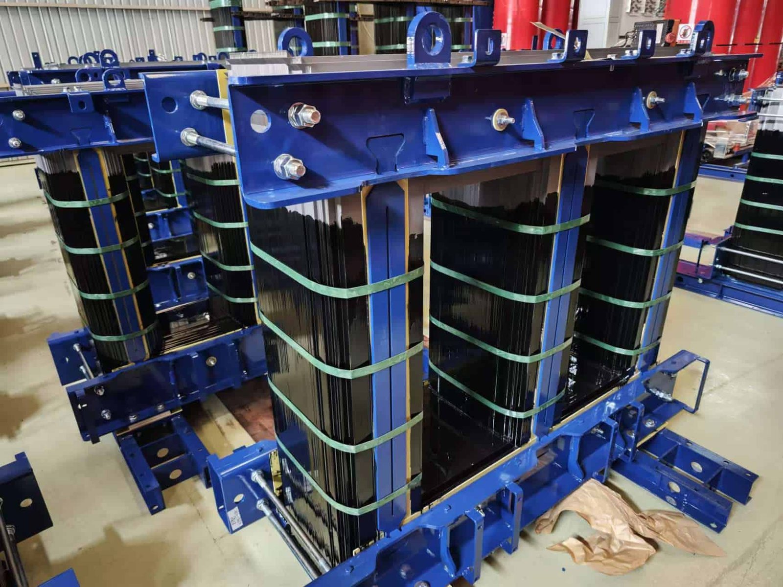
6. Core Assembly and Insulation Integration
In dry-type transformers:
- Core limbs are tightly wound and clamped
- Core is vacuum impregnated or cast in epoxy to minimize vibration and noise
- Magnetic shielding may be applied to prevent flux leakage
Insulation must be:
- Thermally compatible (Class F or H)
- Mechanically stable
- Resistant to moisture and UV (especially for outdoor dry-types)
📌 The core’s magnetic and thermal behavior must be balanced with winding insulation and cooling design.
7. Environmental and Efficiency Considerations
| Concern | Material Impact |
|---|---|
| Energy efficiency mandates | Favor amorphous or nanocrystalline cores |
| Weight & volume constraints | Favor high Bmax materials like CRGO |
| Sustainability goals | Reduced core losses = lower CO₂ footprint |
| Noise-sensitive areas | Smooth hysteresis curves = quieter operation |
EU Ecodesign, U.S. DOE 2016, and India’s IS 1180 standards all drive the use of low-loss core materials in distribution applications.
Why Is CRGO Silicon Steel Commonly Used?
In transformer design, achieving a balance between cost, efficiency, thermal performance, and manufacturability is key. Cold-Rolled Grain-Oriented (CRGO) silicon steel has become the dominant core material in power and distribution transformers because it delivers precisely that balance. It combines excellent magnetic properties in the rolling direction, low hysteresis losses, and high saturation flux density—all critical for efficient magnetic flux conduction in transformers. If inferior materials are used instead, the result is excessive core loss, increased operating temperature, larger physical size, and reduced energy efficiency.
CRGO silicon steel is commonly used in transformer cores because it provides high magnetic permeability and low core losses along the grain direction due to its grain-oriented crystalline structure. This reduces hysteresis and eddy current losses, making transformers more energy efficient, compact, and thermally stable. Its laminated construction minimizes eddy currents, and its ability to operate at high flux densities allows for reduced core size and lower total cost of ownership.
This makes CRGO steel the ideal material for the majority of power and distribution transformers globally.
CRGO silicon steel has a grain orientation aligned with magnetic flux to reduce energy losses.True
The rolling process aligns the grains in the direction of magnetic flux, which enhances permeability and lowers hysteresis loss.
CRGO steel is less efficient than non-oriented silicon steel in transformer applications.False
Grain-oriented steel has significantly lower losses than non-oriented steel due to its directional magnetic properties.
Using CRGO steel reduces transformer core size and heat generation.True
The high saturation flux density and low loss characteristics of CRGO steel allow for smaller, cooler-running transformer cores.
1. What Is CRGO Silicon Steel?
Cold-Rolled Grain-Oriented (CRGO) silicon steel is a specialized magnetic steel that undergoes a precise rolling and annealing process to align its crystal grain structure along one direction—typically the rolling direction.
| Property | CRGO Silicon Steel |
|---|---|
| Silicon content | 2% – 3.5% |
| Grain alignment | Longitudinal (rolling direction) |
| Magnetic permeability | Very high along grain |
| Hysteresis loss | Low in rolling direction |
| Eddy current loss | Reduced by lamination and insulation coating |
| Thickness | 0.23 mm – 0.30 mm (typical) |
The result is a material that conducts magnetic flux efficiently, resists magnetization losses, and minimizes internal heating.
2. Magnetic Benefits of Grain Orientation
| Magnetic Property | Grain-Oriented Steel | Non-Oriented Steel |
|---|---|---|
| Magnetic permeability | Very high (in grain) | Moderate (isotropic) |
| Hysteresis loss | Low | Higher |
| B-H curve | Narrow | Wider (more loss) |
| Magnetizing current | Lower | Higher |
| Efficiency | Higher | Lower |
Grain orientation helps minimize energy wasted as heat during magnetic field reversals—critical for transformers that run continuously.
3. Loss Reduction Mechanism
Total core losses consist of:
- Hysteresis loss (due to magnetic domain switching)
- Eddy current loss (due to circulating currents in the steel)
CRGO steel minimizes these via:
- Thin laminations (0.23–0.30 mm) to reduce eddy paths
- High resistivity from silicon content to limit current flow
- Insulating coatings between laminations
| Core Material | Typical Core Loss at 1.5 T / 50 Hz (W/kg) |
|---|---|
| CRGO (M3 grade) | 1.0 – 1.3 |
| CRGO (HiB grade) | 0.7 – 0.9 |
| Amorphous metal | 0.2 – 0.3 |
| CRNGO | 2.0 – 2.5 |
✅ CRGO delivers excellent performance while remaining cost-effective and mechanically durable.
4. High Flux Density Capability
CRGO steel supports saturation flux densities of up to 1.8 Tesla, which enables:
- Smaller core cross-sections
- Lower copper winding volume
- Reduced transformer size and weight
This is particularly important in applications where space and efficiency are at a premium.
5. CRGO in Laminated Core Construction
Transformers use CRGO sheets in laminated stacks, commonly arranged in:
| Lamination Type | Purpose |
|---|---|
| Step-lap cores | Reduce air gaps and losses at joints |
| Mitered cores | Enhance magnetic continuity at corners |
| 3-phase core limbs | Balanced flux and reduced vibration |
Each lamination is coated with insulating varnish to prevent eddy currents between layers.
6. Noise and Vibration Reduction
CRGO steel’s smooth magnetic transitions reduce magnetostriction—a cause of transformer hum.
| Feature | Result |
|---|---|
| Aligned grains | Uniform magnetic domain movement |
| Reduced magnetostriction | Quieter operation |
| Less core expansion/contraction | Lower mechanical stress |
📌 Especially valuable for urban substations, hospitals, and noise-sensitive zones.
7. Manufacturing and Standardization
CRGO grades are standardized by IEC, ASTM, and JIS:
| Standard | Typical Grades |
|---|---|
| IEC 60404-8-7 | M-3, M-4, M-5, Hi-B |
| ASTM A876 | Grades 7-10 |
| JIS G 3316 | 20H, 23H, 27H, etc. |
Manufacturers like Nippon Steel, POSCO, Baowu, and AK Steel produce high-grade CRGO materials globally.
8. Applications of CRGO Steel in Transformers
| Application | Typical Size Range | Benefits |
|---|---|---|
| Distribution Transformers | 25 kVA – 2.5 MVA | High efficiency, cost-effective |
| Power Transformers | 3 MVA – 1000 MVA | High flux capability, compact core |
| Dry-Type Transformers | Indoor/outdoor | Thermal stability and low noise |
| Instrument Transformers | Low voltage | Precision and reliability |
What Are the Typical Coil Conductors Made Of?
The conductor material in a transformer’s coil windings is a key factor determining efficiency, heat dissipation, size, cost, and longevity. A poorly selected conductor—either in material or geometry—can result in excessive power losses, overheating, or failure under fault conditions. Therefore, selecting the proper conductor is not just a design formality—it's central to reliable electrical performance and transformer lifespan.
Transformer coil conductors are typically made of copper or aluminum, selected based on electrical conductivity, thermal performance, mechanical strength, cost, and application. Copper is preferred for high-performance, compact transformers due to its superior conductivity and mechanical robustness, while aluminum offers a lighter and cost-effective alternative, often used in distribution transformers. Both materials are shaped as round wires, rectangular strips, or foil, and are coated with enamel or wrapped in insulating paper or fiberglass for dielectric protection.
The choice between copper and aluminum must consider the electrical current, physical constraints, cost targets, and mechanical durability required in service.
Copper has higher conductivity and strength compared to aluminum, making it preferred for most transformer windings.True
Copper's high electrical and thermal conductivity ensures lower losses and better short-circuit strength.
Aluminum is more commonly used in distribution transformers due to its lower cost and acceptable performance at lower currents.True
Aluminum reduces initial cost and weight, making it attractive for low-to-medium voltage applications.
Transformer windings can be made without insulation if the voltage is low.False
All windings must have insulation to prevent electrical breakdown, regardless of voltage class.
1. Copper: The Premium Choice for Performance
Copper is the most widely used conductor material in high-performance transformers because of its:
- High electrical conductivity (~58 MS/m)
- Excellent thermal conductivity (~385 W/m·K)
- Superior mechanical strength (useful during short circuits)
- Long-term oxidation resistance
| Parameter | Copper |
|---|---|
| Conductivity | ~100% IACS |
| Density | 8.96 g/cm³ |
| Cost | Higher |
| Size of conductor | Smaller cross-section required |
| Losses | Lower at same current |
| Melting point | 1085°C |
Application Areas:
- Power transformers
- Compact dry-type transformers
- High-reliability installations
- Windings subject to high short-circuit stresses
2. Aluminum: A Lightweight, Cost-Effective Option
Aluminum is about 60% the conductivity of copper but also significantly lighter and less expensive.
| Parameter | Aluminum |
|---|---|
| Conductivity | ~35 MS/m (\~61% IACS) |
| Density | 2.70 g/cm³ |
| Cost | ~50% of copper |
| Thermal conductivity | ~235 W/m·K |
| Size of conductor | ~1.6x larger than copper (for equal current) |
| Melting point | 660°C |
Advantages:
- Lower cost
- Reduced transformer weight
- Easy to extrude into foil or strip
- Widely used in pad-mounted and pole-mounted distribution transformers
Drawbacks:
- Lower mechanical strength
- Higher losses (larger cross-section needed)
- Requires stronger connections to mitigate galvanic corrosion
3. Conductor Types by Shape and Arrangement
| Conductor Form | Used In | Benefits |
|---|---|---|
| Round Wire | Small distribution transformers | Easy winding, good for low voltages |
| Rectangular Strip | Medium–large power transformers | Space-efficient, lower eddy losses |
| Foil Windings (copper/aluminum) | LV windings, especially in dry-type transformers | Uniform current density, reduced hotspots |
| Multilayer/Disk Windings | HV coils | Better voltage distribution, reduced surge stress |
📌 Winding geometry directly affects leakage reactance, heat distribution, and insulation design.
4. Insulation Applied to Coil Conductors
Regardless of conductor material, insulation is critical to prevent turn-to-turn or layer-to-layer short circuits.
| Insulation Type | Application | Temp Class |
|---|---|---|
| Enamel (polyester, polyimide) | Round/rectangular wires | Class F/H |
| Kraft paper | Oil-immersed transformers | Class A |
| Nomex® / Mylar® | High-temperature dry-type transformers | Class H |
| Fiberglass + Resin | Cast resin transformers | Class F/H |
📌 Thermal class should match or exceed transformer operating limits to ensure insulation longevity.
5. Performance Comparison Table: Copper vs. Aluminum
| Property | Copper | Aluminum |
|---|---|---|
| Conductivity | Higher | Lower |
| Weight | Heavier | Lighter |
| Cross-sectional size | Smaller | Larger |
| Cost | Higher | Lower |
| Strength | Higher short-circuit withstand | Weaker under stress |
| Joint reliability | Better | Needs special terminals |
| Oxidation | Slower | Faster (forms Al₂O₃) |
| Applications | Power, industrial | Distribution, economy units |
6. Thermal and Electrical Impact on Sizing
To maintain the same resistive losses:
$$
A{\text{Al}} \approx 1.6 \times A{\text{Cu}}
$$
Where:
- $A_{\text{Al}}$ = cross-section of aluminum conductor
- $A_{\text{Cu}}$ = cross-section of copper conductor
However, larger aluminum conductors may reduce winding space, impacting the overall transformer design.
7. Industry Trends and Selection Criteria
| Design Consideration | Preferred Material |
|---|---|
| Compact size | Copper |
| Low cost | Aluminum |
| Harsh environment | Copper (more corrosion resistant) |
| Mobile/portable units | Aluminum (lighter weight) |
| Short-circuit resilience | Copper |
| Eco-efficient solutions | Both (if properly designed) |
Many modern transformers are engineered with hybrid designs, using copper in HV windings and aluminum in LV to balance performance and cost.
What Type of Insulation Is Applied on the Coils?
Coil insulation is one of the most critical elements in transformer design. While the conductor carries the electrical current, it is the insulation that protects against voltage breakdown, dielectric failure, and thermal degradation. A failure in insulation often leads to arc faults, fires, and catastrophic breakdowns. Therefore, selecting the proper insulation type—not just by material, but also by thermal class, dielectric strength, and mechanical resilience—is fundamental for safe and reliable transformer operation.
The types of insulation applied to transformer coils include enamel coatings, thermally upgraded paper, polyester films, Nomex® aramid paper, mica tape, fiberglass, and epoxy resins. These are chosen based on voltage class, temperature rating, winding geometry, and transformer type. Oil-immersed transformers typically use paper and enamel insulation, while dry-type transformers use a combination of Nomex, fiberglass, mica, and resin systems for higher thermal stability and moisture resistance. Each insulation type is classified according to its thermal endurance class (A, B, F, H, etc.) defined by IEC and IEEE standards.
Proper insulation ensures dielectric integrity, mechanical strength, and long service life under electrical and thermal stress.
Dry-type transformers use different insulation materials than oil-immersed transformers.True
Dry-type designs require materials resistant to open air and higher temperatures, while oil-immersed units use cellulose-based insulation submerged in oil.
All coil insulation must meet specific thermal classes to ensure reliable performance over time.True
Each insulation material must conform to IEC 60085 or IEEE C57.12.01 thermal classification to withstand continuous heating.
Transformer coils can be used without insulation if operating at low voltage.False
Even at low voltages, insulation is critical to prevent turn-to-turn faults and ensure dielectric protection.
1. Enamel-Coated Wire (Magnet Wire)
| Feature | Description |
|---|---|
| Application | Primarily used on round or rectangular conductors |
| Material | Polyurethane, polyesterimide, polyamide-imide coatings |
| Thermal Class | Class B (130°C), F (155°C), or H (180°C) |
| Voltage Range | Low to medium voltage windings |
| Advantages | Thin, flexible, good adhesion, high dielectric strength |
| Used In | Distribution transformers, dry-types, control transformers |
📌 Often the first insulation layer before wrapping or impregnating with other materials.
2. Kraft and Thermally Upgraded Paper (TUP)
| Feature | Description |
|---|---|
| Application | Oil-immersed transformers |
| Material | Cellulose-based insulation paper |
| Thermal Class | Class A (105°C), or thermally upgraded for 120–130°C |
| Dielectric Strength | Excellent in oil (15–20 kV/mm) |
| Used In | Distribution/power transformers (oil-filled) |
🛢 Must be used in conjunction with insulating oil to function properly.
3. Polyester Film and Polyimide Films (e.g., Mylar®, Kapton®)
| Material | Use | Temp Class |
|---|---|---|
| Polyester Film (PET) | Interlayer insulation | Class B (130°C) |
| Polyimide Film (Kapton) | High-temp windings | Class H (180°C) |
| Laminated Films | Combined with Nomex or paper | Multi-purpose barriers |
📌 Flexible, high-dielectric films used between layers or phases.
4. Nomex® (Aramid Paper)
| Feature | Description |
|---|---|
| Thermal Class | Class H (180°C) |
| Structure | Non-woven aramid fiber sheet |
| Resists | Moisture, corona, flame, thermal degradation |
| Used In | Dry-type transformer coils, high-temp windings |
🛡 Used as phase barriers, interlayer insulation, or wrap for LV/HV coils.
5. Fiberglass Insulation (Glass Yarn or Mat)
| Feature | Description |
|---|---|
| Thermal Class | Class F (155°C) or H (180°C) |
| Form | Yarn, sleeves, or woven tape |
| Mechanical Strength | High tensile and abrasion resistance |
| Dielectric Strength | ~8–10 kV/mm |
| Used In | Structural reinforcement, insulation wrapping, coil edge support |
📌 Often impregnated with resin or varnish for rigidity and bonding.
6. Mica Tape (Phlogopite or Muscovite)
| Application | Description |
|---|---|
| HV insulation | Excellent arc and corona resistance |
| Construction | Mica paper + fiberglass carrier + resin binder |
| Thermal Endurance | Up to 220–240°C (Class H or higher) |
| Dielectric Strength | Extremely high (30–50 kV/mm) |
🧯 Used in dry-type transformers for partial discharge suppression and fireproof insulation.
7. Epoxy Resin and Cast Resin Systems
| Type | Use Case | Notes |
|---|---|---|
| VPI (Vacuum Pressure Impregnation) | Distribution and dry-type transformers | Enhances bonding, thermal transfer |
| Epoxy Cast (CRT) | Indoor/outdoor dry-type transformers | Total encapsulation, Class F/H |
| Silicone or Polyurethane Resin | Specialized or flame-retardant types | Often used in traction or marine transformers |
| Benefit | Impact |
|---|---|
| Seals insulation layers | Moisture and contamination protection |
| Mechanically stabilizes coils | Short-circuit withstand and vibration damping |
| Increases thermal conductivity | Enhances heat dissipation |
8. Thermal Class and Selection Chart
| Thermal Class | Max Temp (°C) | Typical Materials |
|---|---|---|
| A | 105°C | Kraft paper, enamel |
| B | 130°C | Polyester, enamel |
| F | 155°C | Fiberglass, resin |
| H | 180°C | Nomex, polyimide, mica |
| C | >220°C | Mica/glass/silicone composites |
📌 IEC 60085 and IEEE C57.12.01 define thermal endurance and classification.
9. Layered Insulation Strategy in Transformer Coils
Transformers typically use multi-layer insulation systems:
- Primary turn insulation: Enamel or polyimide film
- Interlayer insulation: Nomex, polyester film, or paper
- Interphase insulation: Nomex barriers or mica-tape
- Overall coil insulation: Fiberglass + resin coating or epoxy casting
This layered approach ensures redundancy, mechanical protection, and thermal resilience.
10. Insulation Selection Depends on Transformer Type
| Transformer Type | Preferred Coil Insulation |
|---|---|
| Oil-immersed | Kraft paper, enamel, thermally upgraded cellulose |
| Dry-type (VPI) | Enamel + Nomex + polyester film, fiberglass VPI |
| Cast resin (CRT) | Enamel + mica/glass + epoxy |
| High-frequency | Polyimide, Mylar, Kapton, Nomex |
| Traction/Marine | High-mechanical, fireproof mica-glass or silicone |
How Are Core and Coils Protected from Moisture and Dust?
Moisture and dust are among the most destructive environmental contaminants for transformers. When water vapor or fine particulates infiltrate the core or coils, they degrade insulation, reduce dielectric strength, corrode conductors, and lead to tracking, arcing, or complete electrical failure. In dry-type transformers, which lack the protective oil bath found in oil-filled units, moisture and dust ingress must be proactively controlled through specialized design and material techniques. Without these protections, transformer reliability, safety, and service life are seriously compromised.
Core and coils in transformers are protected from moisture and dust using a combination of insulation materials, encapsulation methods (such as vacuum pressure impregnation or cast resin), enclosure design (IP-rated or sealed), anti-condensation systems, surface treatments, and environmental controls. These strategies ensure the electrical integrity, thermal performance, and mechanical stability of windings and cores by preventing ingress of water vapor and airborne contaminants.
Proper environmental protection is especially critical in humid, dusty, marine, and industrial installations.
Dry-type transformers require active moisture protection since they lack insulating oil.True
Unlike oil-immersed units, dry-type transformers are directly exposed to air, making them vulnerable to ambient humidity and dust.
Coils do not need dust protection if they are fully vacuum impregnated.False
While VPI provides moisture resistance, external dust can still cause tracking or heat buildup unless the enclosure is protected.
Humidity can reduce the dielectric strength of insulation materials.True
Moisture absorbed by insulation lowers its dielectric properties and can lead to premature breakdown.
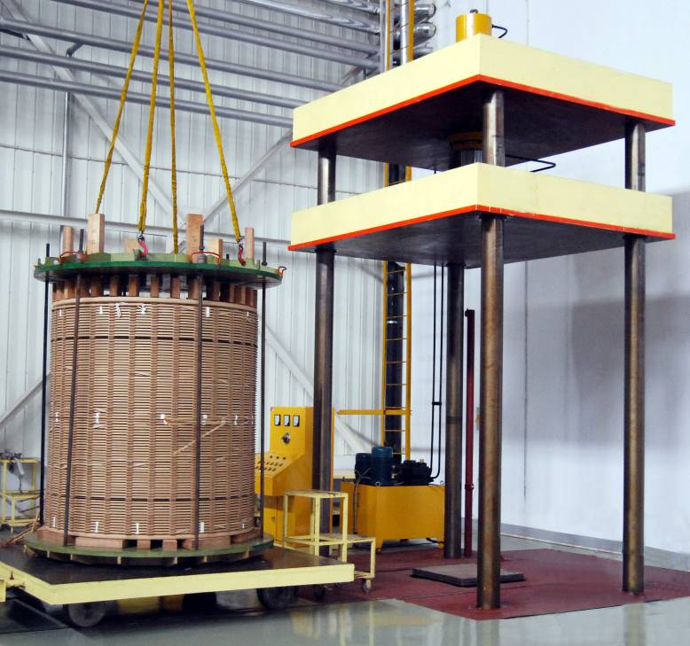
1. Vacuum Pressure Impregnation (VPI): A Moisture Barrier Technique
| Process | Description |
|---|---|
| Vacuum Drying | Removes residual moisture from coils and insulation |
| Resin Impregnation | Under vacuum, thermoset varnish (polyester or epoxy) penetrates the windings |
| Pressure Curing | Ensures resin saturation, fills voids, and bonds insulation layers |
| Thermal Curing | Final hardening at high temperature forms a moisture-resistant film |
Benefits:
- Seals insulation and windings against moisture ingress
- Improves thermal conductivity
- Increases mechanical rigidity and short-circuit strength
- Reduces corona discharge
Applications:
- Indoor dry-type transformers
- Medium-voltage class (up to 36 kV)
- General industrial environments
2. Epoxy Cast Resin Encapsulation: Total Environmental Shielding
| Method | Application |
|---|---|
| Coils are cast in epoxy resin molds | LV and HV coils completely embedded |
| Air gaps eliminated | Prevents condensation, partial discharge |
| Dust-tight and water-resistant | IP54 to IP65 rating possible |
Advantages:
- Totally enclosed coil protection
- Fire-retardant and self-extinguishing (Class F or H)
- High tracking and moisture resistance
- Used in marine, tunnel, mining, desert, and offshore installations
| Property | Value |
|---|---|
| Moisture Absorption | < 0.1% |
| Dielectric Strength | 20–30 kV/mm |
| Thermal Class | F (155°C) or H (180°C) |
📌 Used extensively for outdoor and high-pollution environments.
3. Ingress Protection (IP) Enclosures
| IP Rating | Protection Level |
|---|---|
| IP23 | Limited dust; vertical dripping water |
| IP44 | Dust-protected; splashing water |
| IP54 | Dust-tight; water spray from all directions |
| IP65 | Complete dust ingress prevention; water jet protection |
Transformers are installed in sheet metal enclosures with:
- Sealed gaskets
- Filter ventilation grilles
- Louvered air inlets
- Anti-condensation heaters (in cold climates)
📌 Enclosure choice must match site environmental classification (IEC 60529 or NEMA ratings).
4. Insulation Systems That Resist Moisture
| Material | Moisture Behavior |
|---|---|
| Nomex® (Aramid) | Low hygroscopicity, Class H |
| Fiberglass Epoxy Tapes | Moisture-impervious after curing |
| Mica Tape | High dielectric under humid conditions |
| Enamel Coating | Hydrophobic layer for conductors |
| Silicone-Coated Glass Sleeving | Barrier for terminals and tap connections |
These are used in multi-layer composite insulation systems, tested per IEC 60085 thermal classification.
5. Breathers, Heaters, and Desiccants
In some sealed dry-type or indoor transformers:
| Feature | Function |
|---|---|
| Desiccant Packs | Absorb internal moisture vapor |
| Humidity Indicators | Monitor internal air conditions |
| Anti-Condensation Heaters | Maintain warm air to prevent dew point condensation |
| Ventilation Filters | Trap airborne dust and particulates in forced-air cooling systems |
Especially useful in coastal, tropical, or high-altitude climates.
6. Surface Treatments and Core Protection
| Surface | Treatment |
|---|---|
| Core Laminations | Anti-rust coatings, phosphate treatment, or varnish |
| Coil Edges | Resin sealing or tape wrapping to reduce edge corona |
| Mounting Hardware | Galvanized, powder-coated, or stainless steel |
| HV Terminals | Protected with glass-reinforced bushings and silicone sleeves |
📌 Surface insulation integrity is regularly inspected per IEEE C57.12.01 or IEC 60076-11.
7. Site and Environment Adaptations
| Environment | Recommended Solution |
|---|---|
| Coastal/salty air | Epoxy cast resin coils + IP54 enclosures |
| High humidity (tropical) | VPI + space heaters + ventilation filters |
| Dusty industrial zones | Dust-tight housing, filtered cooling fans |
| Underground/metro | Self-extinguishing resin + forced-air cooling |
| High altitude (>1000 m) | De-rated or pressurized units with air-sealing |
🧪 Routine maintenance includes surface cleaning, humidity checks, and enclosure integrity tests.
8. Testing for Moisture and Dust Resistance
| Test | Standard | Purpose |
|---|---|---|
| Dielectric strength | IEC 60076-11, IEEE C57.12.91 | Verifies insulation integrity |
| Insulation resistance (IR) | >1 GΩ typical | Confirms dry condition of windings |
| Partial discharge (PD) | <10 pC (dry-type) | Detects voids/moisture inside insulation |
| Visual Inspection | Dust, corrosion, humidity ingress | |
| Thermal cycling | Simulates seasonal condensation conditions |
📌 Results help verify dry-state reliability before field commissioning.
How Do These Materials Affect Transformer Lifespan and Efficiency?
A transformer’s performance and service longevity are heavily dictated by the quality and compatibility of materials used in its construction. Improper selection—such as low-grade insulation, subpar core steel, or incompatible conductor materials—can result in accelerated aging, energy losses, hot spots, mechanical deformation, and ultimately, transformer failure. Conversely, when premium materials are selected and engineered correctly, they ensure decades of high-efficiency, low-maintenance service, even in demanding environments.
Transformer materials such as copper or aluminum for windings, CRGO steel or amorphous alloys for cores, and high-grade insulation like Nomex, epoxy resin, and VPI varnish directly affect both lifespan and efficiency. High-conductivity copper minimizes load losses, CRGO steel reduces core losses, and thermal Class H insulation enables operation under elevated temperatures. These materials improve energy transfer, reduce heat buildup, and extend insulation life, ensuring long-term transformer durability and operational efficiency.
Material synergy is the key: the best designs pair materials that work together electrically, thermally, and mechanically.
Material quality is one of the most important determinants of transformer life expectancy.True
Transformer degradation is primarily caused by thermal, dielectric, and mechanical stress—all of which depend on material resilience.
Using cheaper materials like low-grade insulation or steel can save costs without affecting performance.False
Low-grade materials reduce efficiency, increase maintenance, and significantly shorten service life.
High-efficiency core and winding materials can reduce operating costs over the transformer's lifetime.True
Reduced losses translate to lower energy bills and less strain on cooling systems, paying back initial investment.
1. Conductor Material (Copper vs. Aluminum)
| Material | Efficiency Impact | Lifespan Impact |
|---|---|---|
| Copper | Higher conductivity = lower load losses | High mechanical strength = withstands thermal and short-circuit stress better |
| Aluminum | Larger cross-section required = more winding space | More susceptible to oxidation and connection failures if not treated properly |
🔍 Copper is preferred in high-performance, compact transformers, while aluminum is used where cost and weight are prioritized, with design adaptations.
| Parameter | Copper | Aluminum |
|---|---|---|
| Conductivity | 58 MS/m | 35 MS/m |
| Thermal conductivity | 385 W/m·K | 235 W/m·K |
| Strength | High | Moderate |
| Expansion Coefficient | 16.5 µm/m·K | 24 µm/m·K |
Copper helps maintain efficiency across decades by reducing I²R losses, limiting thermal aging.
2. Core Material (CRGO Steel vs. Amorphous Metal)
| Material | Core Losses (W/kg @ 1.5 T) | Thermal Stability | Long-Term Efficiency |
|---|---|---|---|
| CRGO Silicon Steel | 0.90 – 1.30 | Stable | Proven in long-service grid transformers |
| Amorphous Metal | 0.20 – 0.40 | Very stable | Ideal for energy-efficient designs |
Amorphous metal is used in premium designs where no-load loss is a key cost and emissions concern.
Benefits to lifespan:
- Less heat = less insulation stress
- Lower magnetostriction = quieter operation
- Reduces thermal cycling damage
💡 Especially beneficial in renewable power and 24/7 loaded networks.
3. Insulation Material and Thermal Class
| Thermal Class | Max Hot Spot Temp | Typical Material | Lifespan @ Max Temp |
|---|---|---|---|
| Class A | 105°C | Paper, cotton | 20,000 hrs (~2.3 years) |
| Class B | 130°C | Polyester film | 50,000 hrs (~5.7 years) |
| Class F | 155°C | Fiberglass | 100,000 hrs (~11.4 years) |
| Class H | 180°C | Nomex, mica | 180,000 hrs (~20.5 years) |
📌 Each 10°C drop in operating temperature doubles insulation life. Thus, better insulation materials prolong service time exponentially.
High-end materials like Nomex and epoxy-mica systems resist:
- Moisture
- Electrical tracking
- Thermal fatigue
- Fire and smoke propagation
4. Impregnation and Encapsulation Techniques
| Method | Material | Benefits |
|---|---|---|
| VPI (Vacuum Pressure Impregnation) | Polyester/epoxy varnish | Seals against moisture, improves heat dissipation, extends insulation life |
| Cast Resin Encapsulation (CRT) | Filled epoxy resin | Total coil protection from dust, water, salt, chemicals |
| Silicone/Polyurethane Systems | Flexible encapsulation | Used in vibration-prone or mobile transformers |
These techniques prevent hot spots, dielectric breakdown, and premature insulation aging.
📊 Studies show transformers with CRT or VPI systems have MTBF (mean time between failure) > 30 years under nominal load conditions.
5. Mechanical Hardware and Accessories
| Component | Material | Impact |
|---|---|---|
| Core Frame and Fasteners | Stainless steel, epoxy-coated steel | Prevents rust and shorted turns |
| Terminals and Bushings | Brass, silver-plated copper | Low resistance, corrosion-proof |
| Coil Supports | Resin/glass composite | Holds shape, prevents mechanical distortion under thermal stress |
Weak structural materials can lead to coil displacement, arcing, or vibration failure—shortening transformer life.
6. Real-World Efficiency and Lifespan Model
Example: 1000 kVA dry-type transformer
| Scenario | Conductor | Core | Insulation | Full-Load Losses | Expected Life |
|---|---|---|---|---|---|
| Economy Build | Aluminum | CRNGO | Class A | 12.8 kW | ~12 years |
| Standard Build | Copper | CRGO | Class F | 8.9 kW | ~20 years |
| Premium Build | Copper | Amorphous | Class H (Nomex + CRT) | 5.3 kW | >30 years |
Annual savings in power losses (assuming \$0.12/kWh and 70% load factor):
- Economy: $9,417
- Standard: $6,552
- Premium: $3,898
Over 30 years, premium materials can save over \$160,000 in losses and extend lifespan by 2–3x.
7. Environmental and Long-Term Impact
| Factor | Premium Materials Offer |
|---|---|
| Lower CO₂ emissions | Reduced energy losses reduce carbon footprint |
| Lower maintenance | Stable insulation = fewer breakdowns |
| Longer service life | Reduces disposal and replacement cycle |
| Better reliability | Especially under overload or thermal excursions |
High-grade materials also retain value in secondary markets or for refurbishing.
Conclusion
The performance and safety of a dry-type transformer depend heavily on the materials used in its core and coils. From energy-efficient CRGO steel cores to high-conductivity copper windings and high-temperature insulation systems, each component is selected for optimal functionality under various operating conditions. Understanding these materials not only aids in better product selection but also ensures longer service life and operational reliability in demanding environments.
FAQ
Q1: What material is used for the core of a dry-type transformer?
A1: The core of a dry-type transformer is typically made from:
Cold-Rolled Grain-Oriented (CRGO) Silicon Steel
This material:
Has high magnetic permeability
Minimizes hysteresis and eddy current losses
Is laminated to reduce heat and energy loss
Some designs may also use amorphous steel cores for ultra-low-loss applications.
Q2: What materials are used for transformer windings (coils)?
A2: The coils in dry-type transformers are generally made from:
Electrolytic Grade Copper (preferred for its low resistance and high conductivity)
Aluminum (used in cost-sensitive applications or lighter designs)
Both materials are chosen based on application requirements, cost, and weight considerations.
Q3: What insulation materials are used around the coils?
A3: Dry-type transformers use solid insulation systems, such as:
Epoxy Resin (Cast Resin Transformers): Protects against moisture, dust, and corrosive gases
Nomex or Mylar Wrapping: Heat-resistant materials for insulation in VPI (Vacuum Pressure Impregnated) transformers
Polyester or Glass Fiber Tapes: Provide additional thermal and mechanical strength
These materials are flame-retardant and suitable for indoor and harsh environments.
Q4: Why is silicon steel preferred for transformer cores?
A4: Silicon steel is used because it:
Reduces core losses due to its high electrical resistivity
Has directional grain orientation for improved magnetic properties
Supports compact core design with efficient flux conduction
This enhances transformer performance and reduces operational energy losses.
Q5: How do these materials affect transformer performance?
A5: Copper windings: Provide low resistance, improving efficiency and thermal performance
High-grade steel cores: Minimize magnetic losses, ensuring lower no-load loss
Solid insulation: Extends life expectancy, improves fire safety, and allows maintenance-free operation
The combination ensures high mechanical strength, thermal stability, and longevity.
References
Electrical4U: Dry Type Transformer Construction
https://www.electrical4u.com/dry-type-transformer/
IEEE C57.12.01: Standard for Dry-Type Transformers
https://standards.ieee.org/standard/C57_12_01-2020.html
Doble: Materials in Transformer Insulation Systems
https://www.doble.com/resources/transformer-insulation-systems/
NREL: Transformer Core and Coil Optimization
https://www.nrel.gov/docs/fy21osti/dry-transformers.pdf
ScienceDirect: Study on Transformer Material Performance
https://www.sciencedirect.com/science/article/pii/S1359431119311219