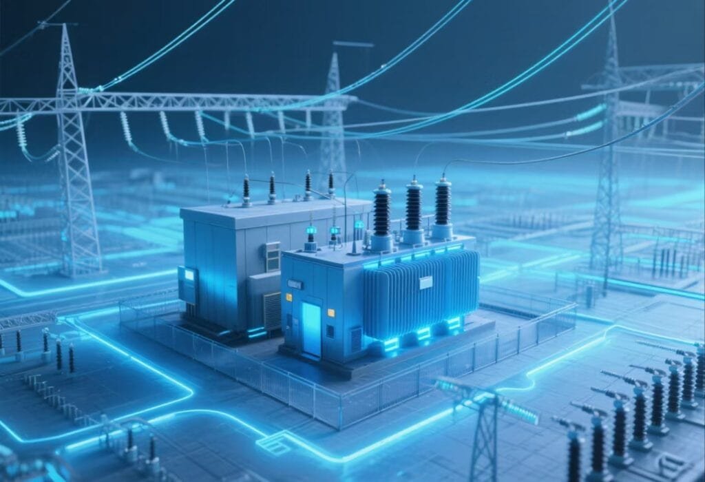
Transformer failures can occur suddenly and without warning, leading to power outages, equipment damage, and even fire hazards. Whether caused by overload, insulation breakdown, short circuits, or external factors such as flooding or vandalism, emergency transformer failures require a rapid, structured response to minimize damage and restore service. This guide outlines the key steps and considerations in responding to transformer emergencies effectively.
What Are the Common Signs of an Emergency Transformer Failure?
Transformer failure can occur suddenly and catastrophically, especially under high load, internal fault conditions, or post-flood stress. These failures may be preceded by early warning signs or occur as instantaneous emergencies, depending on the type of fault—electrical, thermal, mechanical, or dielectric. Recognizing the visual, acoustic, thermal, and olfactory indicators of transformer distress is critical for timely shutdown, public safety, and damage control.
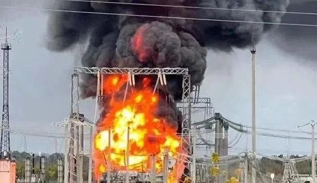
Common signs of emergency transformer failure include loud explosive noises, visible smoke or fire, sparking or arcing at bushings, sudden oil leaks, burnt smell, discoloration of the tank, overheating, and power outage. These symptoms indicate imminent or active internal failure and require immediate isolation and emergency response.
Quick detection and response can prevent injury, environmental damage, and grid collapse.
Transformer failure always happens silently and without visible signs.False
Emergency transformer failures are often accompanied by visible smoke, noise, leaks, arcing, or overheating—making them detectable with proper awareness.
Top Emergency Failure Indicators
| Symptom | Description and Associated Failure Type |
|---|---|
| Loud Bang or Explosion | Indicates internal arcing, gas buildup rupture, or tank rupture |
| Smoke or Fire | Result of oil ignition, insulation combustion, or arc fault |
| Visible Arcing/Sparking | Live flashover near bushings, tap changers, or terminals |
| Sudden Oil Leak | Ruptured gasket or tank breach due to pressure or thermal expansion |
| Overheating or High Temperature | Externally warm surface, radiators abnormally hot |
| Burning or Chemical Smell | Sign of cellulose or oil decomposition under thermal/electrical stress |
| Discoloration or Soot Marks | Evidence of thermal hotspots or previous discharge |
| Buzzing, Popping Sounds | Partial discharge or failing internal components |
| Complete or Partial Power Loss | Sign of winding short, bushing failure, or relay tripping |
Real-World Case: Immediate Failure Symptoms
- Transformer: 1600 kVA, 22/0.4 kV oil-immersed
Symptoms:
- Loud boom and flash at 8:22 AM
- Black smoke from bushing area
- Oil leakage and fire visible at base
- Area experienced power outage
- Response: Unit isolated, fire suppressed, oil contained
Post-inspection showed blown winding and ruptured tank caused by insulation failure.
Monitoring Tools That Detect Emergency Conditions
| Device or Sensor | What It Detects |
|---|---|
| Temperature Sensors (RTDs) | Rapid rise in winding or top oil temperature |
| Buchholz Relay (Oil Units) | Gas accumulation or sudden pressure from internal faults |
| Pressure Relief Device (PRD) | Popped cap signals internal overpressure |
| DGA Sensor (Online) | Detects rise in fault gases like C₂H₂ (arc), CO (insulation burn) |
| Thermal Cameras (IR) | Identifies hot spots or abnormally warm areas |
| Acoustic Emission Detectors | Arcing, partial discharge sound patterns |
What to Do When Emergency Signs Appear
| Step | Reason |
|---|---|
| Isolate the Transformer | Prevents escalation of arcing or thermal runaway |
| Activate Fire Response | Contain and extinguish oil-based fire if safe to do so |
| Alert Control Room | Initiate power rerouting and safety protocol |
| Cordon Off Area | Avoid exposure to hazardous fumes, fire, or high voltage |
| Capture Sensor Data/Footage | Enables forensic fault analysis later |
| Engage Emergency Maintenance Crew | Begin damage control, oil containment, and failure reporting |
Common Emergency Fault Causes
| Failure Category | Trigger Mechanism |
|---|---|
| Dielectric Failure | Moisture, aging insulation, or overvoltage |
| Thermal Overload | Sustained overheating or cooling system failure |
| Internal Arcing | Loose connections, PD, or winding damage |
| Mechanical Deformation | Fault current forces twist or deform winding alignment |
| Oil Contamination | Loss of BDV → arc ignition in oil chamber |
| Lightning or Surge | External impulse through bushing or ground path |
Early Signs That Precede Emergency Failures
| Symptom | Early Warning Stage |
|---|---|
| Drop in Insulation Resistance (IR) | Indicates moisture or insulation degradation |
| Unusual Smell on Site | Oxidized oil or heated resin from partial discharge |
| Unbalanced Voltage or Current | Possible winding fault or core shorting |
| Rising Oil Acidity or Moisture | Predicts paper breakdown or oil sludging |
| Increased Transformer Noise | May signal core clamp loosening or magnetic unbalance |
What Should Be the First Steps Immediately After a Transformer Failure?
A transformer failure—whether due to electrical arcing, overheating, insulation breakdown, or oil ignition—can be explosive, damaging, and dangerous. The first few minutes after a failure are critical to ensure personnel safety, contain environmental risks, and prevent secondary equipment loss. A clear emergency protocol must be followed to isolate the fault, protect the public, and start technical and forensic assessment for repairs or replacement.
Immediately after a transformer failure, the first steps include isolating the transformer from all power sources, activating emergency response protocols, securing the site with hazard signage, notifying the control center and safety team, assessing for fire or oil leaks, and preventing public or staff access. Documentation and data collection should follow once the site is safe.
These first steps are crucial to protect lives, minimize damage, and enable effective root cause analysis.
The first response to a transformer failure is to try to restart it quickly.False
Attempting to re-energize a failed transformer without inspection is highly dangerous and may cause fire, arc flash, or equipment destruction. Immediate isolation and inspection are required.
Critical First Steps to Take Within the First 30 Minutes
| Action | Purpose |
|---|---|
| 1. Immediately Isolate the Transformer | Open breakers, fuses, or disconnects to de-energize unit |
| 2. Confirm Power Disconnection | Use voltage testers or relay indicators for verification |
| 3. Activate Emergency Protocols | Initiate utility or site-specific safety plan |
| 4. Secure the Area | Cordon off access with barricade tape or warning signage |
| 5. Notify Operations & Safety Teams | Inform SCADA center, engineers, and response managers |
| 6. Check for Fire or Oil Spill | Deploy extinguishers or containment kits as needed |
| 7. Document Incident Details | Record time, location, symptoms, and any visual indicators |
Key Safety Tasks to Protect Personnel and Public
| Task | Importance |
|---|---|
| Evacuate Area if Needed | Arc flash and oil fires may reignite or spread |
| Don PPE Before Site Entry | Use arc-rated suits, gloves, and insulated tools |
| Avoid Standing Oil or Smoke Zones | Transformer oil vapors and smoke are toxic or flammable |
| Disconnect Secondary Loads | Prevent backfeeding from downstream loads |
| Disable Nearby Power Circuits | Avoid cascading damage through parallel transformers |
Post-Isolation Diagnostic Preparation
| Step | Goal |
|---|---|
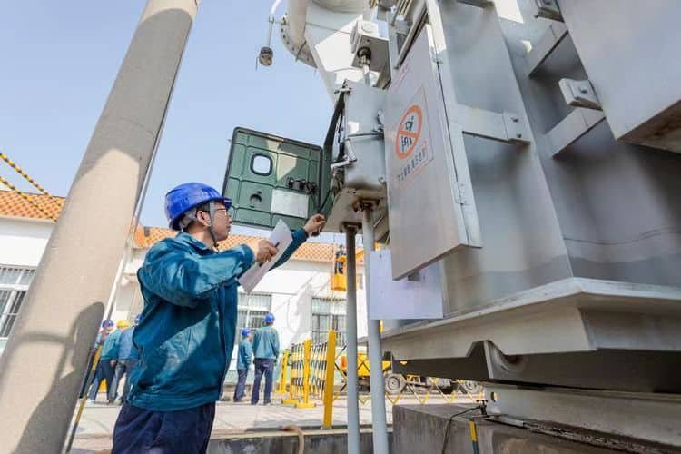
| Visual Inspection from Distance | Look for burn marks, soot, cracks, or blown bushings |
| Check Protection Relay Logs | Understand fault timing and type (e.g., overcurrent, BDV trip) |
| Capture Infrared or Photo Evidence | Useful for insurance and engineering analysis |
| Confirm Buchholz Relay or PRD Activation | Indicates internal arc or gas evolution in oil units |
Real-World Response Scenario
- Event: Transformer failure with smoke and loud explosion
Immediate action:
- Power cut within 90 seconds
- Fire extinguished using CO₂ unit
- Oil absorbent pads deployed around base
- Area cordoned off for 4 hours until all readings stabilized
- Relay log showed overcurrent followed by gas trip
- Outcome: No injury, transformer removed for analysis, root cause: insulation degradation
Key success factor: Clear emergency checklist executed by trained crew.
Initial Data to Collect for Failure Report
| Information Field | Use in Diagnosis and Insurance |
|---|---|
| Date and Time of Incident | Links to load and weather data |
| Load Level at Time of Failure | Correlates with thermal stress or overload |
| Ambient Temperature and Humidity | Affects cooling and partial discharge activity |
| Witnessed Symptoms | Smoke, fire, odor, arcing, noises |
| Photos or Videos | Vital for OEM analysis and legal claims |
| Protection Relay Logs | Pinpoint trigger and first-fault location |
Do’s and Don’ts After Transformer Failure
| Do Immediately | Avoid Doing |
|---|---|
| Isolate power and tag out | Never re-energize before full inspection |
| Wear PPE and restrict area | Avoid touching oil, smoke, or debris with bare hands |
| Report to central operations and safety | Don’t assume the cause—wait for testing |
| Begin safe documentation | Don’t allow media or public into the site without clearance |
Who Should Be Notified and Involved in the Response to a Transformer Failure?
When a transformer fails—especially in a public or critical grid location—it sets off a multi-disciplinary response. Timely communication and role activation are essential to ensure safety, equipment containment, service restoration, and legal compliance. A transformer failure is not just an engineering problem—it’s an operational, environmental, and safety issue, requiring coordination across technical, emergency, regulatory, and support functions.
In the event of a transformer failure, the following parties should be notified and involved: the utility control center (SCADA/dispatch), on-site maintenance or engineering teams, safety and fire response units, environmental or hazardous materials teams (if oil leakage occurs), OEM support (for failure diagnostics), and public authorities (if public safety is affected). Each role is critical in managing containment, communication, and recovery.
A fast, structured notification plan helps prevent delays, secondary damage, and regulatory violations.
Only technical staff need to be informed after a transformer failure.False
Transformer failures often involve fire risk, oil spills, and public safety concerns—requiring coordinated action from safety, emergency, and environmental teams alongside engineers.
Primary Roles and Notification Sequence
| Role/Entity | When to Notify | Responsibility in Response |
|---|---|---|
| SCADA/Control Room Dispatch | Immediately | Isolate power, confirm alarm, alert field crew |
| Field Engineering/Maintenance | Within minutes | Inspect fault, assess damage, secure the site |
| Site Safety Officer | Alongside engineering team | Coordinate lockdown, PPE, public safety |
| Fire/Rescue or Emergency Services | If smoke, fire, or oil ignition involved | Suppress flames, prevent spread, control access |
| Environmental/Hazmat Team | If oil leak or soil/water risk present | Deploy spill containment, remove contaminated material |
| OEM or Transformer Manufacturer | Within first day (or after first analysis) | Guide root cause analysis, approve re-energization plan |
| Regulatory/Utility Compliance Authority | If incident escalates or affects public | Reportable incident forms, documentation, investigation |
Internal Notification Flowchart (Utility Example)
- Transformer Fault Detected (SCADA Alarm)
- ➤ SCADA Notifies Maintenance Team and Field Crew
- ➤ Field Crew Notifies Safety Officer
- ➤ If Smoke/Oil Leak/Fire → Alert Fire Department + Environmental Services
- ➤ Confirm Damage ➤ Notify OEM and Regulatory if applicable
- ➤ Begin Secure Isolation, Inspection, and Site Documentation
Contact Lists Recommended at Every Substation/Utility Yard
| Contact Type | Should Include |
|---|---|
| Technical Escalation Tree | Lead engineer, transformer specialist, substation supervisor |
| Safety/EHS Team Directory | Shift officer, hazmat lead, medical responder contact |
| Emergency Response Team (ERT) | Fire team, oil spill team, confined space/arc response crew |
| OEM Emergency Hotline | Direct line to transformer manufacturer or service division |
| Environmental Agency Contact | Required for spills over defined volume |
| Police/Public Notification | Used if transformer failure endangers roadways or structures |
Example: Coordinated Response Scenario
- Event: Oil-immersed transformer explosion at 33/11 kV urban substation
Response Team Notified:
- SCADA and control center (isolated within 1 min)
- Maintenance and safety officer (on-site in 10 min)
- Fire department (flame visible, suppressed in 20 min)
- Hazmat crew (100 L oil contained)
- OEM notified same day for post-mortem analysis
- Public authority blocked access to substation street
Outcome: Zero injury, successful containment, root cause traced to insulation breakdown
Documentation to Be Collected by Notified Teams
| Team | Must Collect |
|---|---|
| Engineering | Fault logs, relay data, load profile, visual inspection |
| Safety/ERT | PPE records, time of arrival, fire/incident report |
| Environmental | Oil containment log, disposal manifest, soil test results |
| OEM/O\&M Records | Maintenance history, insulation test results, load duty |
| Regulators | Final incident report, impact summary, root cause finding |
How to Diagnose the Root Cause of a Transformer Failure?
After a transformer failure—especially if it’s sudden or catastrophic—determining the root cause is essential for preventing recurrence, validating warranty claims, restoring service safely, and refining asset management strategies. Root cause analysis (RCA) is a structured engineering process that involves data collection, visual inspection, electrical testing, oil/gas analysis, and mechanical assessment. The goal is to trace failure not just to a symptom (e.g., short circuit), but to the underlying degradation, event, or stressor that initiated the breakdown.
To diagnose the root cause of a transformer failure, utilities and engineers should perform a systematic inspection involving: protection relay and SCADA log review, Dissolved Gas Analysis (DGA), oil and moisture testing, insulation resistance and winding tests, thermographic imaging, physical inspection of core/windings, and failure pattern analysis. These combined tools help pinpoint whether the failure was electrical, thermal, mechanical, or environmental.
Each data point contributes to a forensic reconstruction of failure, guiding safe repairs and future design decisions.
Transformer failure diagnosis can rely solely on visual inspection.False
Visual signs are only one part of failure analysis. Electrical testing, gas analysis, and oil chemistry are essential for identifying internal faults or hidden causes.
Root Cause Diagnostic Workflow
| Step | Objective |
|---|---|
| 1. Collect Event Data | Review protection relay records, SCADA logs, ambient conditions |
| 2. Visual and Thermal Inspection | Look for burn marks, leak points, or thermal stress zones |
| 3. Sample and Analyze Oil | Perform DGA, moisture, acidity, and dielectric strength tests |
| 4. Electrical Testing | Conduct insulation resistance, TTR, winding resistance, and HV tests |
| 5. Mechanical/Structural Inspection | Assess deformation, winding shifts, bushing failure |
| 6. Identify Fault Pattern | Compare failure signs to known fault modes (e.g., overvoltage, PD) |
| 7. Final Root Cause Mapping | Correlate all findings with operating history and maintenance |
Key Diagnostic Tests and What They Reveal
| Test or Analysis | Diagnostic Insight |
|---|---|
| DGA (Dissolved Gas Analysis) | Identifies arcing, thermal faults, insulation degradation |
| Furan Content in Oil | Indicates paper insulation aging and moisture-induced breakdown |
| Karl Fischer Moisture Test | Quantifies water contamination in oil or paper |
| BDV (Breakdown Voltage) | Evaluates dielectric integrity of insulating oil |
| IR (Insulation Resistance) | Measures condition of winding insulation |
| Winding Resistance | Detects open circuits or poor connections |
| Turns Ratio (TTR) | Identifies tap changer issues or internal short turns |
| Thermographic Imaging | Detects pre-failure hotspots or unequal cooling |
Example – Root Cause Investigation Case
- Transformer: 6.3 MVA, 33/0.4 kV oil-filled unit
- Symptoms: Explosion, smoke, oil leak, sudden power loss
Investigation Findings:
- DGA: High C₂H₂ (acetylene), H₂ → internal arc detected
- Furan: 1.4 mg/L → advanced paper degradation
- Oil moisture: 64 ppm → breach in conservator gasket
- TTR Test: Normal
- IR: <20 MΩ → unsafe
- Conclusion: Moisture ingress → dielectric breakdown → winding arc
Root cause: Breather failure and seal leak allowed water ingress, not visible externally.
Visual Signs vs. Actual Cause
| Visual Indicator | Possible Misleading Assumption | Actual Root Cause Possibilities |
|---|---|---|
| Blown bushing | Surge fault | Moisture in oil causing internal flashover |
| Soot at top cover | Fire origin | Arc inside tap changer or pressure relief device |
| Oil on ground | Overfill or poor maintenance | Tank rupture due to overpressure from arc gas |
| Melted leads | External overload | Internal short due to insulation collapse |
Root Cause Categories
| Category | Examples |
|---|---|
| Electrical | Dielectric failure, arcing, partial discharge, turn-to-turn short |
| Thermal | Cooling system failure, hotspot, overload, blocked radiator |
| Mechanical | Winding displacement, vibration, core clamp loosened |
| Environmental | Moisture ingress, flood exposure, oil contamination |
| Human Error | Wrong tap setting, poor maintenance, missed testing |
| Manufacturing Defect | Resin voids, loose leads, under-cured insulation |
Tools & Equipment for RCA
| Diagnostic Tool | Used For |
|---|---|
| Portable DGA Kit or Lab | Analyzing fault gases in oil |
| Insulation Resistance Tester (Megger) | Checking dry-type or oil-paper insulation |
| BDV Kit | On-site dielectric strength test of transformer oil |
| Winding Resistance Meter | Detecting unbalanced or failed coil sections |
| Infrared Camera (Thermal) | Identifying uneven thermal zones |
| Tap Changer Analyzer | Verifying OLTC contact integrity and switch timing |
Documentation for Diagnostic Report
| Data Element | Why It Matters |
|---|---|
| Relay Trip Logs | Exact fault timestamp and nature (overcurrent, gas, etc.) |
| Maintenance History | Tracks last oil tests, DGA trends, gasket replacements |
| Load and Temperature History | Identifies overloading or peak thermal stress |
| OEM Design Specs | Helps verify failure against design limits |
| Failure Photos and Sample Lab Reports | Support insurance and forensic review |
What Are the Temporary and Long-Term Recovery Options After Transformer Failure?
After a transformer failure, restoring power and stability is urgent—especially when critical loads like hospitals, factories, or substations are affected. Utilities and industrial users must navigate two parallel priorities: (1) quickly restoring service through temporary solutions, and (2) developing a permanent, long-term recovery strategy that ensures reliability and prevents recurrence. Choosing the right combination of short- and long-term responses depends on equipment availability, damage severity, load criticality, and financial constraints.
Temporary recovery options include deploying mobile transformers, bypassing failed units with load transfers, activating emergency spares, or restoring the failed unit via minor repairs or oil reconditioning. Long-term options include full transformer replacement, factory rebuilding, core-coil retrofitting, or redesigning the system to reduce future failure risks. Each path should be evaluated based on load demand, recovery speed, cost, and infrastructure compatibility.
An effective recovery plan blends speed with strategic foresight, restoring service now while preventing future downtime.
Temporary repairs are always sufficient after transformer failure.False
Temporary recovery methods restore power quickly but often lack long-term reliability. A full root cause assessment and permanent solution are essential.
Temporary Recovery Options
| Option | Use Case and Benefit |
|---|---|
| Mobile Substation Transformer | Rapid deployment (typically on trailer), handles temporary load |
| Load Transfer to Parallel Units | Use nearby transformers to pick up load (if capacity allows) |
| Recommissioning an Inactive Spare | If a backup unit is available and tested |
| Oil Dehydration & Minor Repair | Recoverable faults (e.g., moisture, tap arcing) |
| Install Rental Transformer | Bridge power while sourcing permanent replacement |
| Bypass Switching or Reconfiguration | Temporarily reroute loads around failed unit |
Mobile and Modular Transformer Support
| Type | Specs and Application |
|---|---|
| Mobile Transformer (1–60 MVA) | Mounted on trailer, plug-and-play at substation or industrial site |
| Containerized Dry-Type Units | Ideal for indoor or coastal replacement scenarios |
| Fast-Connect Skids | Temporary MV/LV transformers for isolated loads |
| Battery-Backed Temporary Units | Short-term grid stability or backup during repair |
Long-Term Recovery Solutions
| Solution | Application Scope |
|---|---|
| Transformer Replacement | Required if core, windings, or insulation are beyond repair |
| Core-Coil Retrofit in Existing Tank | Retain housing, replace internals to save cost |
| OEM Factory Rebuilding | Full refurbishment with factory warranty (cost-effective for large units) |
| Upgraded New Transformer | Install higher efficiency or environmentally safer unit |
| Load Redistribution Design | Reduce future burden on single transformer by network redesign |
| Submersion-Resistant Installations | For flood-prone or high-risk environments |
Timeline Comparison – Temporary vs. Long-Term
| Action Type | Typical Deployment Timeframe |
|---|---|
| Mobile Transformer | 1–3 days (if unit is prepositioned) |
| Oil Repair + Testing | 2–7 days (with immediate drying equipment) |
| Load Re-routing | <12 hours (if switchgear and plan exist) |
| Factory Rebuild | 2–6 months (depending on severity) |
| New Build | 6–12 months (including design + logistics) |
| Retrofit Core-Coil | 1–3 months (OEM dependent) |
Recovery Planning Decision Tree
Can failed transformer be restored on site?
➤ Yes → Dehydrate oil, repair fault, test thoroughly
➤ No → Proceed to step 2Is a mobile or spare transformer available?
➤ Yes → Install for temporary power
➤ No → Proceed to step 3Can load be redistributed safely?
➤ Yes → Apply switching scheme
➤ No → Notify critical users, initiate rental deploymentLong-Term Plan Initiated
➤ Assess core damage, oil contamination, winding failure
➤ Choose: rebuild, retrofit, or replace
Example – Real-World Temporary and Long-Term Recovery Path
- Event: 5 MVA transformer failure at food processing facility
Day 1–2:
- Transformer isolated
- Load partially transferred to parallel 3 MVA unit
- Mobile unit connected by Day 3
- Day 5: Root cause traced to partial discharge from moisture
- Week 2: Decision made to replace unit with 6.3 MVA dry-type
- Replacement time: 6.5 months including customs
Outcome: Plant resumed 100% output in 3 days with mobile support, future-proofed with upgraded replacement.
Considerations for Selecting Recovery Strategy
| Factor | Temporary Suitability | Long-Term Suitability |
|---|---|---|
| Load Criticality | Very high | Very high |
| Asset Age | <10 years | >15–20 years |
| Damage Extent | Minor (oil/moisture) | Major (core burn, winding melt) |
| Replacement Lead Time | Long | Mandatory |
| Site Constraints | Indoor/high security | Favor modular or sealed replacements |
| Budget Flexibility | Limited | Higher investment returns over time |
How to Document and Prevent Future Transformer Emergencies?

Every transformer emergency—whether a fire, explosion, oil leak, or internal short—should serve as a lesson for future resilience. Proper documentation not only supports insurance, legal compliance, and warranty claims, but also forms the foundation of failure trend analysis, preventive maintenance strategies, and design upgrades. When combined with predictive diagnostics and system audits, documentation becomes a proactive defense tool, helping to eliminate blind spots before they become emergencies.
To document and prevent future transformer emergencies, utilities must follow a structured post-incident process involving detailed event logging, SCADA and protection system data capture, forensic diagnostics, lab testing, root cause reporting, and knowledge transfer. Prevention measures include condition-based monitoring, timely testing, personnel training, maintenance standardization, and emergency response rehearsals.
The best way to stop the next emergency is to learn from the last one—with data, discipline, and diligence.
Transformer failures don’t need formal documentation if service is restored.False
Documenting transformer failures is essential for insurance, compliance, trend analysis, and preventing future incidents through informed maintenance.
Step-by-Step Incident Documentation Process
| Step | Purpose |
|---|---|
| 1. Initiate Emergency Incident Report | Log time, date, symptoms, affected asset |
| 2. Collect Visual Evidence | Photos, videos, thermographic scans of damage or failure zones |
| 3. Retrieve Protection & SCADA Logs | Capture relay trips, current/voltage patterns before failure |
| 4. Record Team Actions | Who responded, isolation time, safety procedures followed |
| 5. Lab Test Samples | DGA, BDV, furan, moisture to identify internal conditions |
| 6. Conduct Root Cause Analysis | Identify technical trigger and underlying contributor |
| 7. Summarize Corrective Actions | Document what was fixed, replaced, tested, and how site was cleared |
Key Fields in a Transformer Failure Report
| Field | Details to Include |
|---|---|
| Transformer Identification | Serial number, rating, manufacturer, installation year |
| Event Description | Type of failure, observed symptoms, environmental conditions |
| Protection System Response | Trip sequence, relay IDs, time stamps, settings |
| Personnel Response Timeline | When isolation, fire control, and inspections were completed |
| Photos/IR Images | Pre/post damage shots, oil condition, leak points |
| Diagnostic Test Results | Oil lab values, IR test logs, gas concentration trends |
| Root Cause Summary | Classified by electrical/thermal/mechanical/environmental factor |
| Final Recommendations | Repair vs. replace, testing upgrades, design improvements |
Preventive Strategies Based on Documentation Insights
| Action Area | Prevention Measures |
|---|---|
| Insulation Monitoring | Periodic DGA, moisture content, furan testing for aging detection |
| Load Management | Review transformer loading profiles; avoid sustained >85% usage |
| Bushing Inspection | Thermal imaging and surface tracking checks every 6–12 months |
| Tap Changer Health Checks | Measure contact resistance and timing in OLTC units |
| Seal and Breather Maintenance | Annual inspection for leaks or silica gel saturation |
| Arc Flash Risk Review | Recalculate arc energy exposure and PPE zones based on last incident |
Real-World Implementation Example
- Utility initiated “Emergency Response Audit Program” after 3 failures in 2 years
Measures taken:
- Introduced digital failure logging via mobile app
- Set up automatic SCADA data backup for 30 minutes before every trip
- Launched quarterly maintenance KPIs tied to incident reduction
- Created library of RCA reports accessible to engineers
Result:
- Transformer failures dropped by 67% over 18 months
- Response time reduced by 40% due to checklist-based drills
Digital Tools for Documentation and Prevention
| Tool Type | Benefit |
|---|---|
| Asset Management Software (AMS) | Tracks test data, service logs, alerts for overdue inspections |
| Transformer Health Index (THI) | Combines oil, load, temp, and age into risk score |
| Mobile Inspection Apps | Simplifies field technician data entry and checklists |
| Cloud-Based DGA Monitoring | Live gas reading trends with predictive alarms |
| SCADA Logging Automation | Captures fault snapshots for each trip event |
| Maintenance Scheduling Platforms | Integrate RCA lessons into forward-looking test plans |
Periodic Emergency Response Review
| Recommended Interval | Purpose |
|---|---|
| Every Failure Incident | Full RCA, training review, policy revision |
| Quarterly | Review of outstanding action items from past failures |
| Annually | Audit readiness of SOPs, contacts, and emergency gear |
| Post-New Installation | Update protection and SCADA settings for new unit |
Conclusion
Handling emergency transformer failures requires both swift action and technical discipline. Immediate isolation of the fault, coordinated communication, and thorough diagnostics are key to preventing escalation. While recovery may involve temporary solutions, long-term reliability depends on proper post-failure analysis and preventive planning. Investing in training, real-time monitoring, and contingency resources can greatly reduce the impact of such high-risk events in the future.
FAQ
Q1: What are the first steps when a transformer fails suddenly?
A1: Immediate actions include:
Isolate the transformer from the power system using circuit breakers or disconnect switches
Evacuate personnel from the area if there's fire, smoke, or noise
Alert maintenance and emergency teams
Secure the area to prevent access and further hazards
Safety is the top priority during an emergency transformer failure.
Q2: How is the cause of the failure identified?
A2: Diagnostic steps include:
Visual inspection for burns, oil leaks, or structural damage
Dissolved Gas Analysis (DGA) if the unit is oil-filled
Insulation resistance (IR) and winding resistance tests
SFRA (Sweep Frequency Response Analysis) to assess mechanical displacement
Thermal imaging to detect hotspots
Accurate diagnosis determines if the transformer is repairable or must be replaced.
Q3: What are the typical causes of emergency transformer failures?
A3: Common causes include:
Overloading or overheating
Short circuits or lightning surges
Insulation breakdown due to aging or moisture
Poor maintenance or undetected minor faults
Oil contamination or leaks in oil-immersed transformers
Prevention through regular testing and monitoring is critical.
Q4: What are the options for restoring power quickly?
A4: Emergency restoration methods:
Activate backup transformers if available
Use mobile/substation transformers for temporary supply
Reroute load through alternate feeder circuits
Fast-track procurement of a replacement unit via supplier agreements
Response time can be reduced with a disaster recovery plan and critical spares inventory.
Q5: How can future transformer failures be minimized?
A5: Prevention strategies:
Implement predictive maintenance using online monitoring systems
Conduct periodic testing (oil analysis, IR, thermal scans)
Maintain load management and cooling systems
Install protection relays and surge arresters
Develop an emergency response protocol for staff training
Proactive maintenance ensures transformer reliability and system resilience.
References
"Emergency Response to Transformer Failures" – https://www.electrical4u.com/transformer-failure-handling
"IEEE C57.125: Guide for Failure Investigation of Power Transformers" – https://ieeexplore.ieee.org/document/8054112
"Doble: Failure Analysis and Condition Monitoring" – https://www.doble.com/emergency-transformer-analysis
"NREL: Transformer Outage Preparedness Plan" – https://www.nrel.gov/docs/fy22ost/transformer-emergency-plan.pdf
"ScienceDirect: Case Studies in Emergency Transformer Recovery" – https://www.sciencedirect.com/transformer-emergency-failure-analysis