High-voltage transformers are at the heart of power transmission systems, enabling the safe and efficient delivery of electricity across long distances. However, designing these transformers is complex due to demanding requirements such as insulation coordination, thermal management, mechanical strength, and compliance with international standards. Addressing these challenges with innovative solutions ensures safety, reliability, and efficiency in modern power grids.
What Are the Main Insulation Challenges in High-Voltage Transformers?
![]()
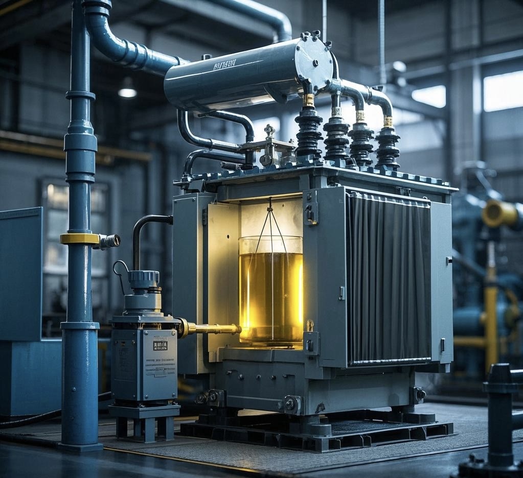
High-voltage transformers face extreme electrical, thermal, and mechanical stresses. Their insulation systems—comprising paper, pressboard, oil, and epoxy composites—are critical to safe operation. However, aging, contamination, electrical discharges, and environmental influences progressively degrade insulation. This degradation can cause partial discharges, dielectric breakdown, and catastrophic failures. When insulation fails, even the most robust transformer becomes unreliable, leading to outages, fires, or total asset loss. The challenge is balancing dielectric strength, thermal endurance, and long-term reliability under high-voltage stress.
The main insulation challenges in high-voltage transformers include dielectric breakdown from electrical stress, accelerated aging due to thermal and moisture effects, partial discharges, contamination of oil or solid insulation, and mechanical deterioration from vibration or short-circuit forces. These factors compromise reliability and efficiency, making insulation monitoring, drying, and maintenance critical for transformer health.
A well-maintained insulation system ensures long service life, but neglect leads to accelerated degradation and failures.
Transformer insulation mainly fails due to conductor overheating only.False
While thermal stress is important, other factors like moisture ingress, electrical stress, and partial discharges are equally critical causes of insulation failure.
Partial discharge activity is an early sign of insulation deterioration in high-voltage transformers.True
Partial discharges create localized electrical stress that accelerates insulation aging and may lead to dielectric breakdown if undetected.
1. Key Insulation Challenges
| Challenge | Description | Impact on Transformer |
|---|---|---|
| Dielectric Breakdown | High voltage stress exceeding material strength | Sudden failure, arc faults |
| Thermal Aging | Heat accelerates cellulose and oil degradation | Reduced dielectric strength, sludge formation |
| Moisture Ingress | Water contamination in oil/paper | Sharp drop in dielectric withstand capability |
| Partial Discharges (PD) | Localized ionization within weak points | Progressive insulation erosion |
| Contamination & Oil Oxidation | Impurities, gases, and sludge in oil | Poor cooling, reduced dielectric properties |
| Mechanical Stress | Short-circuit forces and vibration | Cracks, displacement of windings and barriers |
2. Role of Different Insulation Materials
- Mineral Oil: Provides cooling and dielectric strength, but oxidizes and absorbs moisture.
- Cellulosic Materials (Paper/Pressboard): Affordable and widely used, but thermally weak beyond 105°C.
- Epoxy Resin/Composite Insulation: Higher thermal endurance, suitable for dry-type applications.
- Gas or Synthetic Liquids (e.g., Ester Fluids, SF₆ alternatives): Improved environmental and thermal performance, but costlier.
3. Case Study Example
In a 400 kV, 500 MVA transformer, routine DGA detected high levels of hydrogen and acetylene. Subsequent partial discharge testing confirmed localized insulation degradation near winding leads. Moisture levels in oil exceeded 30 ppm, drastically reducing dielectric strength. Early intervention—oil purification, drying, and barrier reinforcement—restored reliability and avoided a multimillion-dollar catastrophic failure.
4. Monitoring and Diagnostic Methods
- Dissolved Gas Analysis (DGA): Detects electrical faults and overheating of insulation.
- Moisture-in-Oil Sensors: Provides real-time humidity levels.
- Dielectric Frequency Response (DFR): Evaluates insulation condition and aging.
- Partial Discharge Testing: Identifies localized weak points.
- Thermal Imaging: Detects hotspots in winding insulation.
5. Comparative Insulation Challenges
| Condition | With Regular Monitoring | Without Monitoring |
|---|---|---|
| High moisture content | Detected early, corrected with drying | Leads to dielectric collapse |
| PD activity | Identified and mitigated | Causes sudden failure |
| Oil contamination | Filtered and regenerated | Accelerates insulation aging |
| Thermal overload | Controlled via cooling optimization | Leads to irreversible damage |
How Can Thermal Management Be Optimized to Handle Heat Dissipation?
Transformers under heavy or fluctuating loads generate significant heat in their windings, core, and insulation. Poor thermal management leads to accelerated insulation aging, reduced dielectric strength, increased copper and core losses, and shortened lifespan. Excessive heat not only reduces transformer efficiency but also increases the risk of catastrophic failure. As grid demands grow and renewable sources add variability, the challenge of managing transformer temperature has become more pressing. The solution lies in optimized thermal management systems that ensure safe operating temperatures under all load conditions.
Thermal management in transformers can be optimized through advanced cooling technologies (ONAN, ONAF, OFAF, ODAF), intelligent temperature monitoring, enhanced insulation materials, and digital load management systems. By combining passive and active cooling methods with predictive analytics, operators can ensure efficient heat dissipation, extend transformer life, and maintain reliability under variable loads.
This makes thermal optimization not just an engineering requirement, but a cornerstone of transformer safety and efficiency.
Transformer thermal problems are only caused by overloading.False
Even at normal load, poor cooling, high ambient temperatures, or insulation degradation can cause overheating.
Active cooling systems like ONAF and OFAF improve transformer load capacity by enhancing heat dissipation.True
Forced cooling methods allow safe handling of higher loads by removing heat more effectively than passive cooling.
1. Sources of Heat in Transformers
| Heat Source | Description | Impact on Transformer |
|---|---|---|
| Copper Losses (I²R) | Current through windings | Hot-spot heating in coils |
| Core Losses | Hysteresis and eddy currents in steel core | Continuous heating |
| Stray Losses | Leakage flux heating metal parts | Localized hotspots |
| Dielectric Losses | Heating in insulation materials | Insulation aging |
2. Cooling Methods and Their Optimization
| Cooling Method | Code | Description | Typical Application |
|---|---|---|---|
| Natural Air Cooling | AN/ONAN | Heat dissipated through convection | Small distribution transformers |
| Forced Air Cooling | ONAF | Fans improve airflow on radiators | Medium/large power transformers |
| Forced Oil Cooling | OFAF | Pumps circulate oil through radiators | Large HV transformers |
| Directed Oil Cooling | ODAF | Oil forced into windings and core directly | Extra-high voltage transformers |
| Water Cooling | OFWF | Oil-to-water heat exchanger | Space-constrained substations |
Optimization involves selecting the right system for load conditions and integrating dynamic control to run pumps/fans only when needed, reducing auxiliary energy consumption.
3. Intelligent Monitoring for Heat Management
- Hot-Spot Temperature Sensors: Detect winding temperature rise.
- Fiber-Optic Sensors: Embedded in windings for accurate thermal mapping.
- Thermal Models (IEC 60076-7 / IEEE C57.91): Calculate thermal aging factors.
- Digital Twin Integration: Simulates thermal response under forecasted load cycles.
- IoT Cooling Control: Adjusts cooling fan/pump operation in real time.
4. Material Innovations in Thermal Management
- Ester Fluids (Natural & Synthetic): Higher thermal endurance and fire safety.
- Amorphous Core Steel: Reduces no-load losses and heat generation.
- Nanofluid-Enhanced Oils: Improved heat transfer and dielectric performance.
- High-Temperature Insulation (Aramid): Withstands >180°C, extending life under thermal stress.
5. Case Study Example
A 500 MVA, 400 kV transformer at a desert substation faced ambient temperatures above 45°C:
- Conventional ONAN cooling was insufficient; winding hot-spot exceeded 115°C.
- System upgraded to ONAF with IoT-based fan control.
- Fiber-optic sensors provided real-time thermal mapping.
- Oil filtration maintained low moisture for improved cooling performance.
- Result: Peak load capacity increased by 15%, insulation life expectancy extended by 10 years.
6. Comparative Benefits of Optimized Thermal Management
| Without Optimization | With Optimization |
|---|---|
| Frequent overheating | Stable operation |
| Reduced insulation lifespan | Extended insulation life |
| High auxiliary cooling energy | Efficient fan/pump use |
| Limited overload handling | Safe higher load capacity |
| Increased risk of failure | Improved reliability |
What Mechanical Stresses Occur During Faults and How Are They Mitigated?
Transformers are not only exposed to thermal and electrical stresses but also to severe mechanical stresses during faults such as short circuits, inrush currents, and switching surges. These events create enormous electromagnetic forces that act on windings, clamping structures, and insulation systems. If not properly managed, they cause deformation, displacement, insulation cracking, or even catastrophic winding collapse. Mechanical failures are among the top causes of premature transformer outages, making their mitigation a crucial design and maintenance challenge.
During electrical faults, transformers experience intense axial and radial electromagnetic forces on windings, leading to mechanical deformation, conductor displacement, and clamping stress failures. Mitigation involves robust mechanical design (clamping systems, spacers, high-strength conductors), short-circuit withstand testing, advanced insulation supports, and continuous monitoring. These measures ensure the transformer can withstand fault stresses without structural or dielectric failure.
A transformer that resists both electrical and mechanical stresses achieves longer service life and improved fault tolerance.
Mechanical stresses in transformers are negligible compared to thermal stresses.False
Mechanical stresses during faults can be extreme, causing winding displacement or collapse if not mitigated.
Short-circuit withstand testing is essential to verify transformer resistance to fault-induced mechanical stresses.True
This test ensures windings, clamping, and insulation can withstand electromagnetic forces without failure.
1. Sources of Mechanical Stress in Fault Conditions
| Fault Type | Mechanical Stress Generated | Impact on Transformer |
|---|---|---|
| Short Circuit | Axial and radial forces on windings | Deformation, conductor displacement |
| Inrush Current (Magnetizing) | Sudden surge of asymmetrical current | Mechanical shock, loosening of supports |
| Switching Surges | Rapid transient forces | Local insulation and structural stress |
| External Faults | Transmission line short-circuits | Indirect but significant winding forces |
2. Types of Mechanical Stresses
- Axial Forces: Push or pull windings along the vertical axis, risking displacement or compression of insulation spacers.
- Radial Forces: Expand or compress windings, leading to buckling or hoop stress.
- Vibrational Stress: Repeated stress cycles cause fatigue in clamps and spacers.
- Dynamic Stress: Rapid current changes create impact-like mechanical shocks.
3. Mitigation Strategies
Design-Level Measures:
- High-strength copper conductors to resist deformation.
- Rigid clamping and bracing of windings.
- Axial spacers and radial supports to absorb forces.
- Low-leakage reactance designs to reduce fault current magnitude.
Testing & Validation:
- Short-Circuit Withstand Test (IEC 60076-5 / IEEE C57.12.90) simulates extreme fault conditions.
- Frequency response analysis (FRA) detects winding displacement.
Operational Safeguards:
- Protective relays to quickly clear faults.
- Circuit breakers with fast fault interruption.
- Monitoring vibration signatures to identify structural looseness.
4. Case Study Example
A 220 kV, 200 MVA transformer experienced a nearby busbar short circuit. Fault current exceeded 20 times rated current, creating axial forces strong enough to compress winding spacers. Fortunately, the transformer’s reinforced clamping design absorbed the stress, and FRA testing after the event confirmed no winding displacement. Without this robust design, the failure could have caused insulation rupture and a multi-million-dollar replacement.
5. Comparative View of Mitigation
| Without Mitigation | With Mitigation |
|---|---|
| Winding deformation under short circuit | Structural integrity maintained |
| Loosening of clamps/spacers | Rigid supports resist stress |
| Insulation cracks and displacement | Advanced supports maintain dielectric safety |
| Increased risk of catastrophic failure | Safe fault ride-through |
How Do Size, Weight, and Transportation Constraints Affect Design?
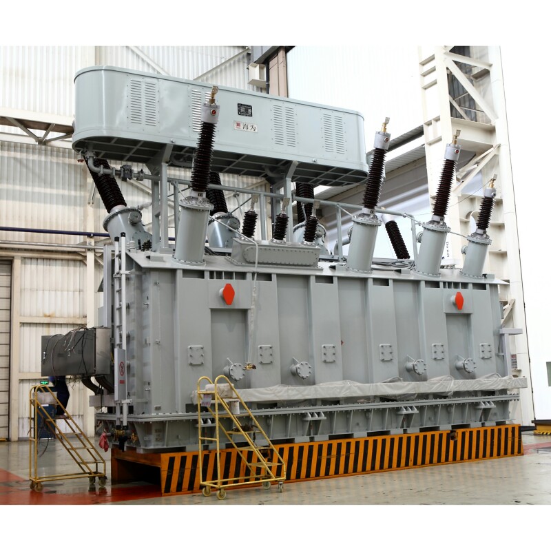
Power transformers are among the heaviest and largest components in the power grid, with units often weighing hundreds of tons. Their sheer size and mass create significant challenges for manufacturing, transportation, installation, and even maintenance. If these constraints are not factored into the design, transformers may be impossible to ship to site, exceed local infrastructure limits, or require costly modifications. Overlooking transportation and dimensional limitations can delay projects, increase costs, and compromise system reliability. The solution lies in designing with transportability and installation logistics in mind from the start.
Size, weight, and transportation constraints affect transformer design by influencing the maximum voltage and power rating, tank and core geometry, modular construction, and cooling system arrangement. Designers must balance electrical performance with physical limitations such as road clearances, bridge load capacities, and shipping regulations. Modular designs, detachable components, and optimized material use help ensure that large transformers can be safely manufactured, shipped, and installed without exceeding practical limits.
By considering these constraints early, manufacturers ensure efficient project execution and reliable transformer operation in the field.
Transformer design is only determined by electrical performance and efficiency.False
Mechanical, logistical, and transportation factors also significantly influence transformer size, shape, and component arrangement.
Modular transformer designs help overcome transportation weight and size limitations.True
By splitting radiators, bushings, or even core assemblies, manufacturers can ship large transformers within transport limits and reassemble them on-site.
1. Physical and Transportation Challenges
| Factor | Constraint | Impact on Transformer Design |
|---|---|---|
| Size (Length, Width, Height) | Road and rail clearance limits | Restricts tank dimensions and core stacking |
| Weight | Bridge load capacities, trailer axle limits | Influences core material choice and modular construction |
| Shipping Method | Road, rail, sea transport | Requires detachable radiators, bushings, and conservators |
| Site Access | Narrow roads, curves, terrain | Determines max transportable dimensions |
| Installation Limits | Crane capacity, foundation strength | Defines max single-lift weight |
2. Design Adaptations to Address Constraints
- Modular Construction: Detachable radiators, bushings, conservators, and even split-core solutions.
- Optimized Materials: Use of high-strength, lightweight steels to reduce tank mass.
- Compact Core Designs: Core-type geometry preferred for reducing tank height.
- Transport-Friendly Shapes: Designing with maximum shipping profile in mind (rail and road clearance).
- Field Assembly: Large transformers shipped in multiple parts and assembled on-site.
3. Case Study Example
A 765 kV, 500 MVA transformer destined for a remote site faced strict transport limits:
- Road bridges allowed a max axle load of 22 tons, with a clearance height limit of 4.5 m.
- Designers created a modular solution with detachable radiators and bushings, reducing shipping weight from 380 tons to 290 tons.
- The transformer was reassembled and tested at site, avoiding costly infrastructure modifications.
- Result: Delivery time was maintained, and installation costs were reduced by 15% compared to redesigning transport routes.
4. Comparative View of Constraint Handling
| Without Transport Consideration | With Transport-Aware Design |
|---|---|
| Oversized units that cannot be shipped | Modular design within clearance and weight limits |
| High project delays due to route restrictions | Smooth logistics and on-time delivery |
| Costly infrastructure upgrades | Optimized on-site assembly |
| Increased mechanical stress during transit | Designed reinforcements for safe transport |
5. Global Standards and Best Practices
- IEC 60076 series: Provides mechanical design requirements including transport stresses.
- AAR & EN Transport Standards: Define dimensional and weight limits for rail and road.
- Utility Guidelines: Many utilities specify maximum shippable sizes (e.g., <400 tons gross).
What Role Do Standards and Testing (IEC, IEEE, ANSI) Play in Ensuring Reliability?
Power transformers are capital-intensive, mission-critical assets in the electrical grid. A single failure can cause multi-million-dollar losses, extended outages, and safety hazards. Without rigorous standards and testing, transformers could suffer from poor design, inadequate insulation, or insufficient fault tolerance. Global organizations such as IEC (International Electrotechnical Commission), IEEE (Institute of Electrical and Electronics Engineers), and ANSI (American National Standards Institute) provide structured frameworks for design, testing, and performance verification. These standards reduce risks, harmonize practices across manufacturers, and ensure transformers meet stringent safety, performance, and reliability requirements before deployment.
Standards and testing by IEC, IEEE, and ANSI play a critical role in ensuring transformer reliability by defining minimum performance requirements, establishing standardized test procedures, and verifying a unit’s ability to withstand electrical, thermal, and mechanical stresses. Compliance guarantees that transformers operate safely under rated conditions, resist short-circuits and overvoltages, and deliver long service life, while enabling interoperability and international trade.
In short, standards act as the blueprint for quality, and testing ensures that every transformer built aligns with that blueprint.
Transformer reliability depends only on manufacturing quality, not on testing standards.False
Standards and testing are essential to verify performance, durability, and compliance, even if the manufacturing process is high-quality.
Short-circuit withstand tests defined by IEC and IEEE are crucial for validating transformer mechanical integrity.True
These tests confirm a transformer can survive fault currents without winding deformation or insulation failure.
1. Key Standards Bodies and Their Roles
| Organization | Scope | Common Transformer Standards |
|---|---|---|
| IEC | International standards for electrical equipment | IEC 60076 series (design, testing, thermal performance, short-circuit strength, eco-design) |
| IEEE | US-based technical standards, widely adopted globally | IEEE C57 series (design, dielectric tests, thermal aging, maintenance guides) |
| ANSI | US standards for industry compliance | ANSI C57 (aligned with IEEE, but includes regulatory compliance aspects) |
2. Critical Types of Testing Required by Standards
| Test Category | Purpose | Example Standard | Reliability Contribution |
|---|---|---|---|
| Type Tests | Verify design for new transformer models | IEC 60076-3, IEEE C57.12.90 | Confirms baseline design safety and performance |
| Routine Tests | Performed on every unit before shipment | IEC 60076-1, IEEE C57.12.90 | Ensures manufacturing quality and consistency |
| Special Tests | Customer-specific or advanced validation | Lightning impulse, short-circuit withstand | Proves endurance under extreme stresses |
| Factory Acceptance Test (FAT) | Joint manufacturer-customer validation | IEC & IEEE frameworks | Reduces risk of field failure |
3. Examples of Essential Reliability Tests
- Dielectric Tests: Power frequency withstand, lightning impulse, switching impulse.
- Thermal Tests: Temperature rise tests to verify cooling performance.
- Short-Circuit Withstand Test: Validates mechanical strength under fault currents.
- DGA Baseline Measurement: Ensures insulation and oil integrity before shipment.
- Noise and Loss Measurements: Confirm compliance with efficiency and environmental directives.
4. Case Study Example
A 400 kV, 500 MVA transformer was subjected to an IEC 60076-5 short-circuit test. The unit experienced forces equivalent to 20 times its rated current. Post-test inspections using Frequency Response Analysis (FRA) confirmed no winding displacement, validating the robustness of its clamping design. The customer gained confidence in operational safety, and the transformer has since operated for 15+ years without a major fault.
5. Comparative Impact of Standards and Testing
| Without Standardized Testing | With IEC/IEEE/ANSI Testing |
|---|---|
| Unknown reliability | Verified performance under stress |
| Higher risk of catastrophic failure | Reduced risk through proven endurance |
| Non-uniform manufacturing | Harmonized quality benchmarks |
| Limited international trade | Easier export/import compliance |
| Shorter asset life | Extended service life validated by tests |
How Are Digital Technologies and Smart Monitoring Improving High-Voltage Transformer Design?
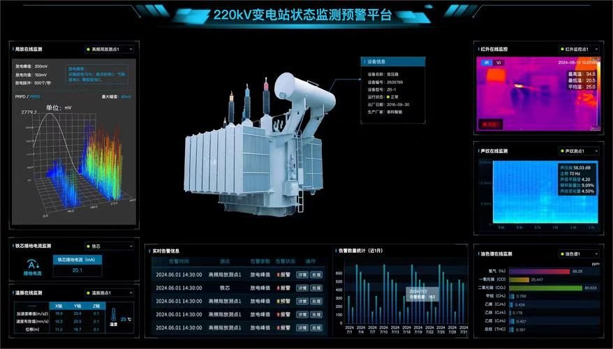
High-voltage transformers are the heart of the transmission grid, yet they face increasing challenges: higher power demands, renewable integration, cyber-physical threats, and stricter efficiency requirements. Traditional transformers were passive, requiring periodic manual inspections that often detected problems too late. This led to unexpected failures, costly outages, and reduced asset lifespan. The solution lies in digitalization and smart monitoring, which transform these static assets into intelligent, self-monitoring systems capable of real-time performance optimization and predictive maintenance.
Digital technologies and smart monitoring improve high-voltage transformer design by embedding IoT sensors, advanced analytics, and digital twins to continuously track key parameters such as temperature, load, insulation condition, and oil quality. These tools enable predictive maintenance, fault prevention, efficiency optimization, and extended service life, making transformers safer, more reliable, and more sustainable in modern grids.
In essence, digitalization shifts transformers from reactive maintenance to proactive intelligence.
High-voltage transformers are still designed only as passive electromechanical devices.False
Modern transformers integrate sensors, IoT, and AI-driven monitoring for proactive management and design improvements.
Smart monitoring can extend transformer lifespan by preventing overheating and insulation degradation.True
Real-time monitoring allows early intervention before critical failures occur, significantly prolonging service life.
1. Key Digital Technologies in Modern Transformer Design
| Technology | Function | Benefit to Reliability and Efficiency |
|---|---|---|
| IoT Sensors | Continuous monitoring of temperature, vibration, oil moisture, and gas levels | Early detection of anomalies, prevents catastrophic failure |
| DGA Online Monitoring | Real-time dissolved gas analysis | Identifies partial discharges, overheating, and incipient faults |
| Digital Twins | Virtual models simulating transformer behavior | Predictive analytics for design optimization and lifetime forecasting |
| Cloud & Edge Computing | Centralized and on-site data processing | Faster decision-making and integration into grid management |
| AI & Machine Learning | Pattern recognition in historical and live data | Predictive maintenance and anomaly detection |
| Cybersecurity Protocols | Protects data and control interfaces | Prevents malicious interference in smart grids |
2. Improvements in Transformer Design Enabled by Digitalization
- Smarter Insulation Systems: Digital thermal models optimize winding arrangements for better cooling.
- Adaptive Cooling Systems: Sensor-driven fans and pumps adjust cooling dynamically to reduce losses.
- Modular Monitoring Interfaces: Digital design ensures compatibility with utility SCADA and smart grids.
- Optimized Material Use: Simulation tools reduce over-dimensioning, lowering weight and costs.
3. Real-World Example
A European utility deployed digital monitoring systems on its 400 kV fleet. IoT sensors tracked:
- Hotspot temperature rises under fluctuating renewable inputs.
- Moisture ingress in oil-immersed transformers.
- Vibration signatures linked to mechanical stresses.
Predictive alerts reduced unplanned outages by 40% and extended mean time between failures (MTBF) by 7 years, while optimizing load distribution during peak demand.
4. Comparative Impact of Smart Monitoring
| Traditional Transformer | Smart Digital Transformer |
|---|---|
| Periodic offline testing | Real-time 24/7 monitoring |
| Failures detected after damage | Predictive fault detection |
| Fixed cooling operation | Adaptive smart cooling |
| High O\&M costs | Reduced lifecycle cost |
| Limited integration with grid | Full integration into smart grid and IoT |
5. Future Trends in Digital Transformer Technology
- Integration with Renewable Energy Forecasting: Load models aligned with wind/solar variability.
- Blockchain-Based Energy Security: Ensuring trusted monitoring records.
- Edge AI: On-site autonomous decision-making without cloud delay.
- Self-Healing Designs: Automated controls that reroute loads or adjust parameters in real-time.
Conclusion
The design of high-voltage transformers involves overcoming multiple challenges—from insulation coordination and thermal management to mechanical stress resistance and logistical constraints. By leveraging advanced materials, robust testing, and intelligent monitoring technologies, manufacturers can deliver reliable, safe, and efficient transformers that meet the growing demands of modern power systems.
FAQ
Q1: What are the main challenges in high-voltage transformer design?
Key challenges include:
Insulation requirements: Preventing dielectric breakdown under extreme voltages.
Thermal management: Controlling heat from copper and core losses.
Mechanical stresses: Withstanding short-circuit forces and transportation vibrations.
Size and weight constraints: Balancing performance with installation limits.
Efficiency standards: Meeting global eco-design and energy efficiency regulations.
Q2: How is insulation managed in high-voltage transformers?
Designers use layered insulation systems, high-quality paper/oil insulation, resin systems (for dry type), and SF6 or ester fluids in special cases. Advanced dielectric testing ensures reliability and prevents partial discharge at high voltages.
Q3: How are thermal challenges addressed?
Cooling methods such as ONAN, ONAF, OFAF, and ODAF are used depending on transformer size and load. High-efficiency radiators, oil pumps, and forced-air systems help manage heat and extend insulation life.
Q4: How do designers handle mechanical stresses in transformers?
High-voltage transformers are built with robust winding clamping systems, strong cores, and vibration-resistant designs. Finite Element Analysis (FEA) and 3D modeling are applied to simulate fault conditions and optimize structural integrity.
Q5: What solutions improve high-voltage transformer efficiency and reliability?
Amorphous or high-grade silicon steel cores reduce no-load losses.
Copper windings minimize resistance compared to aluminum.
Digital monitoring systems track load, temperature, and dissolved gases.
Eco-friendly insulating fluids like natural esters improve fire safety and biodegradability.
Compliance with IEC 60076 and IEEE C57 ensures safety and performance.
References
IEEE Std C57 – High-Voltage Transformer Design and Testing: https://ieeexplore.ieee.org
IEC 60076 – Power Transformer Design Standards: https://webstore.iec.ch
NEMA – Transformer Design and Performance Guidelines: https://www.nema.org
Electrical4U – High Voltage Transformer Design Basics: https://www.electrical4u.com
EEP – Challenges in Power Transformer Design: https://electrical-engineering-portal.com
Doble Engineering – Transformer Testing & Diagnostics: https://www.doble.com
Energy.gov – High Voltage Transformer Efficiency Programs: https://www.energy.gov

